1
SYSTEM OPERATION
NORMAL SEQUENCE OF OPERATION
(90% Two-Stage Variable Speed Models with WhiteRodgers 50V61-288 Integrated Ignition Control)
Power Up
The normal power up sequence is as follows:
1. 115 VAC power applied to furnace.
2. Integrated control module performs internal checks.
3. Integrated control module flashes LED one time.
4. Integrated control module monitors safety circuits continuously.
5. Furnace awaits call from thermostat.
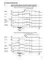
Heating Mode
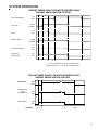
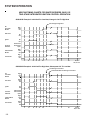
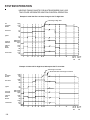
The normal operational sequence in heating mode is as follows:
1. R and W1 (or R and W1 and W2) thermostat contacts
close, initiating a call for heat.
2. Integrated control module performs safety circuit checks.
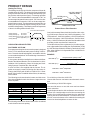
3. Induced draft blower is energized on high speed for a 10second prepurge. Humidifier terminals are energized with
induced draft blower.
4. Induced draft blower steps to low speed following
prepurge. Low stage pressure switch contacts are closed.
5. Ignitor warm up (20 seconds) begins upon step to low
speed and presence of closed low stage pressure switch
contacts.
6. After 20-second ignitor warm up period, low stage gas
valve is energized (4-second ignition trial) delivering gas
to burners and establishing flame. Ignitor remains on for
3 seconds after gas valve is opened (ignition activation
period).
7. Integrated control module monitors flame presence and
control begins timing 30-second heat on delay. Gas valve
will remain open only if flame is sensed.
8. If the thermostat call is for low heat, gas valve and induced draft blower will continue on low stage. If the call
is for high heat, the gas valve and induced draft blower
will change to high stage .
9. Circulator blower is energized on the appropriate heat
speed following a fixed thirty second blower on delay.
The circulator blower requires 30 seconds to ramp up to
full speed. Electronic air cleaner terminals are energized
with circulator blower.
10. Furnace is now operating on the specified stage called
for by the two-stage thermostat.
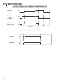
11. Furnace runs, integrated control module monitors safety
circuits continuously.
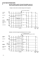
12. If the two-stage thermostat changes the call from low
heat to high heat, the integrated control module will immediately switch the induced draft blower, gas valve, and
circulator blower to their high stage settings.
13. If the two-stage thermostat changes the call from high
heat to low heat, the control will immediately switch the
induced draft blower and gas valve to their low stage
settings. The circulator blower will remain on high heating speed for thirty seconds before switching to the low
heat circulating speed.
14. R and W1 (or R and W1 and W2) thermostat contacts
open, completing the call for heat.
15. Gas valve closes, extinguishing flame.
16. Induced draft blower is de-energized following a fifteen
second post purge. Humidifier terminals are de-energized.
17. Circulator blower continues running for the selected heat
off delay period (60, 90, 120, or 180 seconds). The speed
run during this period depends on the last heat call provided by the thermostat.
If the last call for heat was a call for low heat, the air
circulator blower will run on low heat speed for the duration of the heat off delay period (60, 90, 120, or 180 seconds).
If the last call for heat was a call for high heat, the air
circulating blower will run on the high heating speed for
thirty seconds and then switch to the low heating speed
for the balance of the heat off delay period (30, 60, 90,
or 150 seconds).
18. Circulator blower and electronic air cleaner terminals are
de-energized
19. Circulator blower ramps down to OFF during the 30 seconds following the heat off delay period.
20. Furnace awaits next call from thermostat.
120