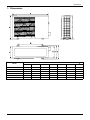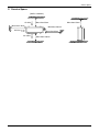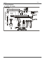
1
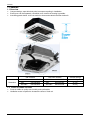
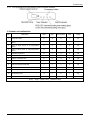
Service Manual MODEL: CCT 50HINVi/o CCT 70HINVi/o CCT 100HINVi/o Contents Part 1 General Information .................................................................................................... 1 Part 2 Indoor Units Part 3 Outdoor Units Part 5 Electrical Control System ĆThe specifications, designs, and information in this book are subject to change without notice for product improvement. Contents i General Information Part 1 General Information 1. Model Lists ................................................................................................. 2 2. External Appearance ................................................................................. 3 2.1 Indoor Units ............................................................................................................ 3 2.2 Outdoor Units ......................................................................................................... 3 4. Features ...................................................................................................... General Information 1 Model Lists 1. Model Lists 1.1 Indoor Units R410A (capacity multiplied by 1000Btu/h) Type Function 18 24 36 Super slim cassette Cooling and heating Ș Ș Ș Duct Cooling and heating Ș Ș Ș Ceiling-floor New Four-way cassette (compact) Cooling and heating Ș Ș Ș Cooling and heating Ș 1.2 Outdoor Units Universal Outdoor unit Model CCT 50HINVo CCT 70HINVo Compressor type Rotary Rotary Compressor Brand GMCC GMCC Matched indoor units CCT 50HINVi DCT 50HINVi CFT 50HINVi CCT 70HINVi DCT 70HINVi CFT 70HINVi CCT 100HINVo 2 Rotary Mitsubishi CCT 100HINVi DCT 100HINVi CFT 100HINVi General Information External Appearance 2. External Appearance 2.1 Indoor Units Super slim cassette Duct Ceiling-Floor Compact Four-way cassette 2.2 Outdoor Units Single fan outdoor unit General Information Double fan outdoor unit 3 Features 4. Features 4.1. To meet Europe A level, actual EER/COP of new product with BLDC motors of indoor & outdoor unit and DC compressor will be higher than 3.4. 4.2. Low ambient kit is standard for outdoor units 4.3. Network control function is standard for the indoor units. 4.4. Standard auto restart function and follow me function. 4.5. Slim cassette with standard remote controller, wire controller and CCM for optional. Med Duct and HESP duct with standard wired controller, remote controller and CCM for optional. 4.6. Standard anti-cold air function. 4.7. Standard auto defrosting function. 4.8. Standard self-diagnose function. 4.9. Standard timer function and sleep mode function controlled by controller. General Information 5 Indoor Units Part 2 Indoor Units Super Slim Cassette Type ....................................................7 6 Indoor Units Super Slim Cassette Type Super Slim Cassette Type 1. Features ............................................................................... 8 2. Dimensions ........................................................................ 12 3. Service Space .................................................................... 13 4. Wiring Diagrams................................................................ 14 5. Electric Characteristics .................................................... 15 6. Sound Levels ..................................................................... 16 7. Accessories ....................................................................... 17 8. The Specification of Power .............................................. 18 9. Field Wiring ....................................................................... 19 Indoor Units 7 Features 1. Features 1.1 Overview ¾ ¾ ¾ Compact design, super slim body size, less space requiring in installation Each louver can be separately controlled, more comfort air blowing is possible. Auto-lifting panel design, more convenient to clean and maintain the filter.(optional) Old Cassette Dimension 18K-24Kφ 30Kφ 36K-48Kφ 840*230*840 840*300*840 840*300*840 New slim cassette Volume change 18K-24Kφ 840*205*840 30Kφ 840*205*840 36K-48Kφ 840*245*840 13.3%Ļ 47.7%Ļ 22.4%Ļ 1.2 Fresh air intake function ¾ ¾ 8 Fresh air fulfills air quality more healthy and comfortable. Ventilation motor is optional to increase the effect of fresh air. Indoor Units Features New air-intake 1.3 Optional ionizer generator ¾ Ionizer generator is optional to get refreshing air to your room. Ionizer generator connector ¾ Ventilation motor connector Ionizer can be switched on or off by remote controller. When pressing the Clean Air button on the remote controller, Ionizer will work and the indicator light on display board will shine. Indoor Units 9 Features 1.4 External air duct design ¾ Reserve external air duct, more flexible for the air supply. 1.5 Built-in draining pump ¾ Due to the improvement of structure, more convenient to repair or replace the draining pump. Draining Pump ¾ 10 Built-in draining pump to make sure condensed water drain out reliably. Indoor Units Features 1.6 Terminals for alarm lamp and long-distance on-off controller connection are standard ¾ Reserve terminals for the connection of alarm lamp and long-distance on-off controller, more human control. Alarm lamp Long-distance on-off controller 1.7 Optional touch-screen wired controller ¾ ¾ Touch screen wired controller is optional, with error code indication function. Better man-machine conversation interface. Undated structure design, 4-way wire layout design, no raised part at backside, more convenient to place the wires and install the device. 1.8 Twins Combination ¾ The units can be installed as Twin systems: one outdoor unit can connect with two indoor units. The indoor units can be combined in any of the different available ratings. Indoor Units 11 Dimensions 2. Dimensions Model 18 24 36 12 A 205 205 245 H >235 >235 >275 Indoor Units Service Space >1000m m >1000mm Indoor Units >1000mm 3. Service Space >1000mm 13 Wiring Diagrams 4. Wiring Diagrams CCT 50HINVi, CCT 70HINVi, CCT 100HINVi. 14 Indoor Units Electric Characteristics 5. Electric Characteristics Indoor Unit Model Hz Power Supply MFA 15 CCT50HINVi 50 Voltage 220-240 Min Max 198 254 CCT70HINVi 50 220-240 198 254 15 CC100HINVi 50 220-240 198 254 15 Notes: MFA: Max. Fuse Amps. (A) Indoor Units 15 Sound Levels 6. Sound Levels P Microphone Model 16 Noise Power dB(A) Noise level dB(A) H M L CCT 50HINVi 58 47 43 36 CCT70HINVi 59 48 44 40 CCT100HINVi 64 54 50 45 Indoor Units Accessories 7. Accessories Name INSTALLATION FITTINGS Tubing & Fittings Drainpipe Fittings Remote controller & Its Frame Others Installation accessory (The product you have might not be provided the following accessories Indoor Units Shape Quantity Installation paper board 1 Bolt M5 4 Soundproof / insulation sheath 2 Out-let pipe 1 Out-let pipe sheath 1 Out-let pipe clasp 1 Remote controller & Its Frame 1 Remote controller holder 1 Mounting screw(ST2.9×10-C-H) 2 Remote controller manual 1 Alkaline dry batteries (AM4) 2 Owner's manual 1 Installation manual 1 Network wires 1 Expansible hook 4 Installation hook 4 Orifice 1 17 The Specification of Power 8. The Specification of Power Model 18000-24000Btu/h 36000 Btu/h 1-phase 1-phase Frequency and Voltage 220-240V, 50Hz 220-240V, 50Hz POWER WIRING (mm2) 3×1.0 3×1.0 CIRCUIT BREAKER (A) 15 15 Phase INDOOR UNIT POWER Phase OUTDOOR UNIT POWER 1-phase 3-phase Frequency and Voltage 220-240V, 50Hz 380-420V, 50Hz POWER WIRING (mm2) 3×2.5 CIRCUIT BREAKER (A) Indoor/Outdoor Connecting Wiring 2 (Weak Electric Signal) (mm ) Indoor/Outdoor Connecting Wiring (Strong Electric Signal) (mm2) 18 5×2.5 30 30 3×0.5 3×0.5 Indoor Units Field Wiring 9. Field Wiring Indoor Units 19 Outdoor Units Part 3 Outdoor Units 1. Dimensions .................................................................................................. 53 2. Service Space .............................................................................................. 55 3. Piping Diagrams .......................................................................................... 56 4. Wiring Diagrams .......................................................................................... 57 5. Electric Characteristics ............................................................................... 60 6. Operation Limits .......................................................................................... 61 7. Sound Levels ............................................................................................... 62 52 Outdoor Units Dimensions 1. Dimensions Unitφmm Model A B C D E F H CCT 50HINVo 842 560 335 360 312 324 695 CCT 70HINVo CCT 100HINVo 895 590 333 355 302 313 862 990 624 366 396 340 354 966 Outdoor Units 53 Service Space 2. Service Space (Wall or obstacle) Air inlet More than 30cm Air inlet More than 60cm Maintain channel More than 60cm Air outlet Outdoor Units More than 30cm More than 200cm 55 Piping Diagrams 3. Piping Diagrams CCT 50HINVo CCT 70HINVo INDOOR OUTDOOR LIQUID SIDE CAPILIARY TUBE Electronic expansion valve 2-WAY VALVE T3 Condenser temp. sensor HEAT EXCHANGE (EVAPORATOR) HEAT EXCHANGE (CONDENSER) T4 Ambient temp. sensor T1 Room temp. sensor T2 Evaporator temp. sensor GAS SIDE 4-WAY VALVE 3-WAY VALVE Accumulator High pressure switch T5 Discharge temp. sensor Low pressure switch COOLING Compressor HEATING CCT 100HINVo INDOOR OUTDOOR LIQUID SIDE CAPILIARY TUBE Electronic expansion valve 2-WAY VALVE T3 Condenser temp. sensor HEAT EXCHANGE (EVAPORATOR) HEAT EXCHANGE (CONDENSER) T4 Ambient temp. sensor T1 Room temp. sensor T2 Evaporator temp. sensor GAS SIDE 4-WAY VALVE 3-WAY VALVE Accumulator Compressor Low pressure switch Oil return Capillary 56 High pressure switch T5 Discharge temp. sensor Oil separator COOLING HEATING Outdoor Units Wiring Diagrams 4. Wiring Diagrams CCT 50HINVo, CCT 70HINVo Outdoor Units 57 Wiring Diagrams CCT 100HINVo 58 Outdoor Units Electric Characteristics 5. Electric Characteristics Outdoor Unit Model CCT50HINVo 60 Hz 50 CCT70HINVo 50 CCT100HINVo 50 Voltage Min. 220-240V 198V 220-240V 198V 380-415V 342V Max. 254V 254V 440V Outdoor Units Operation Limits 6. Operation Limits Temperature Mode Room temperature Outdoor temperature Cooling operation Heating operation Ő17đ 30đ -15đЊ50đ -15đЊ24đ CAUTION: 1. If the air conditioner is used beyond the above conditions, certain safety protection features may come into operation and cause the unit to operate abnormally. 2. The room relative humidity should be less than 80%. If the air conditioner operates beyond this figure, the surface of the air conditioner may attract condensation. Please set the vertical air flow louver to its maximum angle (vertically to the floor), and set HIGH fan mode. 3. The optimum performance will be achieved during this operating temperature zone. Outdoor Units 61 Sound Levels 7. Sound Levels Outdoor Unit Microphone H 1.0m Note: H= 0.5 × height of outdoor unit Model 62 Sound Power dB(A) CCT 50HINVo 65 CCT 70HINVo 69 CCT 100HINVo 70 Outdoor Units Test operation 11. Test operation 11.1 The test operation must be carried out after the entire installation has been completed. 11.2 Please confirm the following points before the test operation. ¾ ¾ ¾ ¾ ¾ ¾ ¾ ¾ ¾ ¾ The indoor unit and outdoor unit are installed properly. Tubing and wiring are correctly completed. The refrigerant pipe system is leakage-checked. The drainage is unimpeded. The ground wiring is connected correctly. The length of the tubing and the added stow capacity of the refrigerant have been recorded. The power voltage fits the rated voltage of the air conditioner. There is no obstacle at the outlet and inlet of the outdoor and indoor units. The gas-side and liquid-side stop values are both opened. The air conditioner is pre-heated by turning on the power. 11.3 Test operation Set the air conditioner under the mode of "COOLING" by remote controller, and check the following points. Indoor unit ¾ Whether the switch on the remote controller works well. ¾ Whether the buttons on the remote controller works well. ¾ Whether the air flow louver moves normally. ¾ Whether the room temperature is adjusted well. ¾ Whether the indicator lights normally. ¾ Whether the temporary buttons works well. ¾ Whether the drainage is normal. ¾ Whether there is vibration or abnormal noise during operation. Outdoor unit ¾ Whether there is vibration or abnormal noise during operation. ¾ Whether the generated wind, noise, or condensed of by the air conditioner have influenced your neighborhood. ¾ Whether any of the refrigerant is leaked. Installation 93 Electrical Control System LFIS-B-1211 Part 5 Electrical Control System 1. Electrical Control Function .......................................95 2. Troubleshooting .......................................................104 3. Controller ..................................................................133 94 Electrical Control System Electrical Control Function 1. Electrical Control Function 1.1 Definition T1: Indoor room temperature T2: Coil temperature of indoor heat exchanger middle. T2B: Coil temperature of indoor heat exchanger outlet. T3: Coil temperature of condenser T4: Outdoor ambient temperature T5: Compressor discharge temperature 1.2 Main Protection 1.2.1 Time delay at restart for compressor. 1.2.2 Temperature protection of compressor top The unit will stop working when the compressor top temp. protector cut off, and will restart after the compressor top temp. protector restart. 1.2.3 Temperature protection of compressor discharge When the compressor discharge temp. is getting higher, the running frequency will be limited as below rules: ----If 102đ<T5<115đ, decrease the frequency to the lower level every 2 minutes till to F1. ---If T5>115đ for 10 seconds, the compressor will stop and restart till T5<90đ. 1.2.4 Sensor protection at open circuit and breaking disconnection. 1.2.5 Indoor fan delayed open function When the unit starts up, the louver will be active immediately and the indoor fan will open 10s later. If the unit runs in heating mode, the indoor fan will be also controlled by anti-cold wind function. 1.2.6 Fan Speed is out of control(for DC motor) When Indoor Fan Speed keeps too low (For A5 duct&Ceiling&floor,300RPM,For Super slim cassette,200RPM) for 50s, the unit will stop and the LED will display the failure Electrical Control System 95 Electrical Control Function 1.3 Operation Modes and Functions 1.3.1 Fan mode (1) Outdoor fan and compressor stop. (2) Temperature setting function is disabled, and no setting temperature is displayed. (3) Indoor fan can be set to high/(med)/low/auto. (4) The louver operates same as in cooling mode. (5) Auto fan: 5.0 High 4.0 Medium 3.0 2.0 Low Ts=24 1.3.2 Cooling Mode 1.3.2.1 Outdoor PMW open angle control The unit is working in cooling mode with the EXV open 300P for 3 minutes, then adjusting PMW open angle according to the temperature of compressor discharge every 2 minutes. 1.3.2.2 Outdoor fan running rules 7 ć $ '&B)$1B+,B63'B$'' % '&B)$1B0,'B63'B$'' & '&B)$1B0,1B63'B$'' ' '&B)$1B6/2:B63'B$'' ( '&B)$1B66/2:B63'B$'' ć ć ć ć ć ć ć 1.3.2.3 Indoor fan running rules In cooling mode, indoor fan runs all the time and the speed can be selected as high, medium, low and auto. The auto fan: 96 Electrical Control System Electrical Control Function 5.0 High 4.0 Medium 3.0 2.0 Low 1.3.2.4 Evaporator low temperature T2 protection. When T2<2ć and lasts for 3 minutes, the indoor has no capacity demand and resume till T2Ő7ć. 1.3.2.5 Condenser high temperature T3 protection When T365đ for 3 seconds, the compressor will shut off. When T3ψ52,the compressor will restart. 1.3.3 Heating Mode 1.3.2.1 Outdoor PMW open angle control The unit is working in heating mode with the EXV open 300P for 3 minutes, then adjusting PMW open angle according to the temperature of compressor discharge every 2 minutes. 1.3.3.2 Outdoor fan running rules: 7 ć ( '&B)$1B66/2:B63'B$'' ' '&B)$1B6/2:B63'B$'' & '&B)$1B0,1B63'B$'' % '&B)$1B0,'B63'B$'' $ '&B)$1B+,B63'B$'' ć ć ć ć ć ć ć 1.3.3.3 Indoor fan running rules: When the compressor is on, the indoor fan can be set to high/(med)/low/auto. And the anti-cold wind function has the priority. Auto fan action: Electrical Control System 97 Electrical Control Function T1-Ts-ǻT Low -2 -3 Medium -4 -5 High Anti-cold Wind Function: 7 TE5 Setting fan speed TE6 TE2 Low TE3 TE1 Breeze TE4 Fan off 1.3.3.4 Defrosting modeφ Condition of defrosting: 7 7LPH ć 7LPH Time conditions: time1 Time conditions(Meet the following conditions) 1.Running in heating mode 2. T43ć 3. Compressor is on 4. T3TempEnterDefrost_ADD ć Cleared conditions (Meet any one of the following conditions) 1. Compressor is off. 2. T3˚TempEnterDefrost_ADD ć Time2 Time conditions(Meet the following conditions) 1.Running in heating mode 98 Electrical Control System Electrical Control Function 2. T4<3ć 3. Compressor is on 4. T3TempEnterDefrost_ADD ć Cleared conditions (Meet any one of the following conditions) 1. Compressor is off and T3˚TempEnterDefrost_ADD +2ć last for 20 minutes 2. Running in cooling mode. 3. Compressor is off for 1 hour. Condition of entry defrosting: time1+ time240 minutes, When defrosting is end,time1 and time2 are cleared. Defrosting actionφ 4-Way valve no longer than 10min Compressor Indoor fan TimeA 10S 10S 30S Outdoor fan PMV running 8 mins with 300P PMV 480P Condition of ending defrosting: If any one of following items is satisfied, defrosting will stop and the machine will turn to normal heating mode. Ś The defrosting time achieves 10min; ĸ T3 ı15ć; Ĺ T3 ı7ć for 60seconds. 1.3.3.5 High evaporator coil temp.T2 protection: T2>60đ, the compressor will stop and restart when T2<54đ. 1.3.4 Auto-mode This mode can be chosen with remote controller and the setting temperature can be changed between 17~30đ. In auto mode, the machine will choose cooling, heating or fan-only mode according to ǻT (ǻT =T1-Ts). Electrical Control System 99 Electrical Control Function ǻT=T1-Ts Running mode ǻTŐ2đ Cooling -1ǻT<2đ Fan-only ǻT<-1đ Heating Indoor fan will run at auto fan of the relevant mode. The louver operates same as in relevant mode. If the machine switches mode between heating and cooling, the compressor will keep stopping for 15 minutes and then choose mode according to T1-Ts. If the setting temperature is modified, the machine will choose running function again. 1.3.5 Drying mode Drying mode works the same as cooling mode in low speed. All protections are active and the same as that in cooling mode. 1.3.6 Timer function 1.3.6.1 Timing range is 24 hours. 1.3.6.2 Timer on. The machine will turn on automatically when reaching the setting time. 1.3.6.3 Timer off. The machine will turn off automatically when reaching the setting time. 1.3.6.4 Timer on/off. The machine will turn on automatically when reaching the setting “on” time, and then turn off automatically when reaching the setting “off” time. 1.3.6.5 Timer off/on. The machine will turn off automatically when reaching the setting “off” time, and then turn on automatically when reaching the setting “on” time. 1.3.6.6 The timer function will not change the AC current operation mode. Suppose AC is off now, it will not start up firstly after setting the “timer off” function. And when reaching the setting time, the timer LED will be off and the AC running mode has not been changed. 1.3.6.7 The setting time is relative time. 1.3.7 Economy function 1.3.7.1 The sleep function is available in cooling, heating or auto mode. 1.3.7.2. Operation process in sleep mode is as follow: When cooling, the setting temperature rises 1đ (be lower than 30đ) every one hour, 2 hours later the setting temperature stops rising and the indoor fan is fixed at low speed. When heating, the setting temperature decreases 1đ (be higher than 17đ) every one hour, 2 hours later the setting temperature stops rising and indoor fan is fixed at low speed. (Anti-cold wind function has the priority). 1.3.7.3 Operation time in sleep mode is 7 hours. After 7 hours the AC quits this mode but doesn’t turns off 1.3.7.4 Timer setting is available 100 Electrical Control System Electrical Control Function 1.3.8 Auto-Restart function The indoor unit is equipped with auto-restart function, which is carried out through an auto-restart module. In case of a sudden power failure, the module memorizes the setting conditions before the power failure. The unit will resume the previous operation setting (not including Swing function) automatically after 3 minutes when power returns. 1.3.9 Drain pump control (For Duct & Cassette) Adopt the water-level switch to control the action of drain pump. Main action under different condition :( every 5 seconds the system will check the water level one time) 1. When the A/C operates with cooling (including auto cooling) and forced cooling mode, the pump will start running immediately and continuously, till stop cooling. 2. Once the water level increase and up to the control point, LED will alarm and the drain pump open and continue checking the water level. If the water level fall down and LED disalarmed (drain pump delay close 1 minute) and operate with the last mode. Otherwise the entire system stop operating ( including the pump) and LED remain alarming after 3 minutes, 1.3.10 Follow me 1) If the indoor PCB receives the signal which results from pressing the FOLLOW ME button on remote controller, the buzzer will emit a sound and this indicates the follow me function is initiated. But when the indoor PCB receives signal which sent from remote controller every 3 minutes, the buzzer will not respond. When the unit is running with follow-me function, the PCB will control the unit according to the temperature from follow-me signal, and the temperature collection function of room temperature sensor will be shielded. 2) When the follow-me function is available, the PCB will not respond according to the setting temperature from follow-me signal every 3 minutes. 3) The PCB will take action to the mode change information from remote controller signal, and the follow-me function will be turned off. (if the wired remote controller does not initiate follow me function). 4) When the unit is running with follow-me function, if the PCB doesn’t receive any signal from remote controller for 7 minutes or pressing FOLLOW ME button again, the follow-me function will be turned off automatically, and the temperature collection function of room temperature sensor will be available, the PCB will control the unit according to the room temperature detected from its own room temperature sensor and setting temperature. 5) When the indoor PCB receives the follow-me signal from wired remote controller, the control is the same as that from wireless remote controller, but buzzer will not respond. When the PCB receives turning-off follow-me signal from wired remote controller, the unit will quit follow-me function at once. The follow-me function controlled by wired remote controller prevails that by wireless remote controller. Electrical Control System 101 Electrical Control Function 1.3.11 Point Check Function There is a check switch in outdoor PCB. Press the switch SW1 to check the states of unit when the unit is running. Press the switch N times it will display the content corresponding to No. N. After getting into the check function, it will display No. N with 1.5s, meanwhile the low bit decimal of digit display flashing, indicated to get into the check function display. After 1.5s, it will display the content corresponding to No. N. the digital display tube will display the follow procedure when push SW1 each time. N Display Remark 00 Normal display 01 Indoor unit capacity demand code 02 04 Amendatory capacity demand code The frequency after the capacity requirement transfer The frequency after the frequency limit 05 The frequency of sending to 341 06 Indoor unit evaporator outlet temp.(heating T2θ cooling T2B) 07 Condenser pipe temp.(T3) 08 Outdoor ambient temp.(T4) 09 Compressor discharge temp.(Tp) 10 AD value of current 11 AD value of voltage 12 Indoor unit running mode code Off:0, Fan only 1,Cooling:2, Heating:3 13 Outdoor unit running mode code 14 EXV open angle 15 Frequency limit symbol Off:0, Fan only 1,Cooling:2, Heating:3, Forced cooling:4 Actual data/4. If the value is higher than 99, the digital display tube will show single digit and tens digit. For example ,the digital display tube show “2.0”,it means the EXV open angle is 120×4=480p.) Frequency limit Bit7 caused by IGBT radiator Frequency limit Bit6 caused by PFC The display value is hex Frequency limit Bit5 number. For example, caused by T4. the digital display tube Frequency limit Bit4 show 2A,then Bit5=1, caused by T2. Bit3=1, Bit1=1. Frequency limit It means frequency limit Bit3 caused by T3. caused by T4,T3 and Frequency limit current. Bit2 caused by Tp. Frequency limit Bit1 caused by current Frequency limit Bit0 caused by voltage 16 DC fan motor speed 03 102 Display running frequency, running state or malfunction code Actual data*HP*10 If capacity demand code is higher than 99, the digital display tube will show single digit and tens digit. (For example, the digital display tube show “5.0”,it means the capacity demand is 15. the digital display tube show “60”,it means the capacity demand is 6.0) If the temp. is lower than 0 degree, the digital display tube will show “0”.If the temp. is higher than 70 degree, the digital display tube will show “70”. If the temp. is lower than -9 degree, the digital display tube will show “-9”.If the temp. is higher than 70 degree, the digital display tube will show “70”. If the indoor unit is not connected, the digital display tube will show: “ʊʊ” The display value is between 13~129 degree. If the temp. is lower than 13 degree, the digital display tube will show “13”.If the temp. is higher than 99 degree, the digital display tube will show single digit and tens digit. (For example, the digital display tube show “0.5”,it means the compressor discharge temp. is 105 degree. the digital display tube show “1.6”,it means the compressor discharge temp. is 116 degree) The display value is hex number. Electrical Control System Electrical Control Function 17 IGBT radiator temp. 18 Indoor unit number The display value is between 30~120 degree. If the temp. is lower than 30 degree, the digital display tube will show “30”.If the temp. is higher than 99 degree, the digital display tube will show single digit and tens digit. (For example, the digital display tube show “0.5”,it means the IGBT radiator temp. is 105 degree. the digital display tube show “1.6”,it means the IGBT radiator temp. is 116 degree) The indoor unit can communicate with outdoor unit well. 19 Condenser pipe temp. of 1# indoor unit If the temp. is lower than 0 degree, the digital display tube will 20 Condenser pipe temp. of 2# indoor unit show “0”.If the temp. is higher than 70 degree, the digital display tube will show “70”. If the capacity demand is 0, , the digital display tube will show “0. If the indoor unit is not 21 Condenser pipe temp. of 3# indoor unit 22 1# Indoor unit capacity demand code 23 2# Indoor unit capacity demand code 24 3# Indoor unit capacity demand code Electrical Control System connected, the digital display tube will show: “ʊʊ”(heating T2θcooling T2B) Actual data*HP*10 If capacity demand code is higher than 99, the digital display tube will show single digit and tens digit. (For example, the digital display tube show “5.0”,it means the capacity demand is 15. the digital display tube show “60”,it means the capacity demand is 6.0). If the indoor unit is not connected, the digital display tube will show: “ʊʊ” 103 Troubleshooting 2. Troubleshooting 2.1 Display board 2.1.1 Icon explanation on indoor display board (Super slim cassette). 2.1.2 Icon explanation on indoor display board (A5 Duct) PRE-DEF indicator(cooling and heating type) or fan only indicator(cooling only type) Timer indicator Alarm indicator Operation lamp Infrared signal receiver Display digital tube Temporary button MANUAL OPERATION TIMER DEF./FAN ALARM 2.1.3 Auto-lifting panel of 4 way cassette 2.1.4 Display board of Ceiling-floor indoor unit 104 Electrical Control System Troubleshooting 2.1.5 Icon explanation on indoor display board (Compact cassette). 2.2 Indoor unit malfunction NO. Malfunction Defrosting lamp Alarm lamp Running lamp Timer lamp Display(digital tube) 1 Communication malfunction between indoor and outdoor units. X X X ƿ E1 2 Open or short circuit of T1 temperature sensor X X ƿ X E2 3 Open or short circuit of T2 temperature sensor X X ƿ X E3 4 Open or short circuit of T2B temperature sensor X X ƿ X E4 5 Full-water malfunction X ƿ X X EE 6 Indoor EEPROM malfunction ƿ X X X E7 7 Outdoor unit malfunction X Ƽ X X Ed 8 Indoor fan speed is out of control ƿ ƿ X X E8 9 Communication malfunction between main PCB and up-down panel PCB ƿ ƿ ƿ X F0 10 Up-down panel malfunction ƿ ƿ X ƿ F1 11 Up-down panel is not closed ƿ ƿ X O F2 12 Communication malfunction between master unit and slave unit X ƿ X ƿ F3 13 Other malfunction of master unit or slave unit X ƿ ƿ X F4 O (on) Electrical Control System X(off) ƿ(flash at 5Hz) Ƽ(flash at 0.5Hz) 105 Troubleshooting 2.3 Outdoor unit malfunction Display Malfunction or Protection E0 Outdoor EEPROM malfunction E2 Indoor / outdoor units communication error E3 Communication malfunction between IPM board and outdoor main board E4 Open or short circuit of T3 or T4 temperature sensor E5 Voltage protection of compressor E6 PFC module protection (For MOU-36HFN1-QRC4,MOU-36HFN1-QRC8) P0 Top temperature protection of compressor P1 High pressure protection (For 36k models) P2 Low pressure protection(For 36k models) P3 Current protection of compressor P4 Discharge temperature protection of compressor P5 High temperature protection of condenser P6 IPM module protection P7 High temperature protection of evaporator In low ambient cooling mode, the LED displaysćLCĈ or alternative displays between running frequency and “LC”(each displays 0.5s) 106 Electrical Control System Troubleshooting 2.4 Solving steps for typical malfunction 2.4.1 For the indoor unit 2.4.1.1 Open or short circuit of temperature sensor Check the connections between temperature sensor and PCB. Are the connections good? No Correct the connections. Yes Check the resistance value of the sensor via Appendix 1 Is it normal? Yes Replace indoor or outdoor PCB. No Replace the sensor Electrical Control System 107 Troubleshooting 2.4.1.2. Outdoor unit malfunction 108 Electrical Control System Troubleshooting 2.4.1.3. Indoor EEPROM malfunction Shut off the power supply and turn it on 5 seconds later. Is it still displaying the error code? Yes If the EEPROM chip is welded on PCB, replace the PCB directly. Otherwise, check whether the EEPROM chip plugged in PCB well? No Insert the EEPROM well Yes Replace the indoor PCB. 2.4.1.4. Full-water malfunction Electrical Control System 109 Troubleshooting 2.4.1.5. Indoor fan Speed has been out of control. (Only for the units used DC motor) DC motor voltage input and output (control chip is inside the motor) DC motor voltage input and output NO. 1 2 3 4 5 6 110 Color Red --Black White Yellow Blue Signal Vs/Vm --GND Vcc Vsp FG Voltage 192V~380V --0V 13.5-16.5V 0~6.5V 15V Electrical Control System Troubleshooting Control chip is in main PCB NO. 1 2 3 4 5 Color Orange Grey White Pink Black Signal Hu Hv Hw Vcc GND Color Red Blue Yellow Signal W V U 1) Release the UVW connector. Measure the resistance of U-V, U-W, V-W. If the resistance is not equal to each other, the fan motor must have problems and need to be replaced. Otherwise, go to step 2. 2) Power on and when the unit is in standby, measure the voltage of pin4-5 in feedback signal connector. If the value is not 5V, change the PCB. Otherwise, go to step 3. 3) Rotate the fan by hand, measure the voltage of pin1-5, pin 2-5 and pin 3-5 in feedback signal connector. If any voltage is not positive voltage fluctuation, the fan motor must have problems and need to be replaced. Electrical Control System 111 Troubleshooting 2.4.2 For the super-slim cassette with up-down panel 2.4.2.1 Communication error between indoor unit and up-down panel 2.4.2.2 Up-down panel is defective 112 Electrical Control System Troubleshooting 2.4.2.3 Up-down panel is not closed Electrical Control System 113 Troubleshooting 2.4.3 For the unit with TWINS function(For the super-slim cassette & A5 duct) 2.4.3.1 Communication failure between master unit and indoor unit 114 Electrical Control System Troubleshooting 2.4.4 For the outdoor unit 2.4.4.1. E0 malfunction Electrical Control System 115 Troubleshooting 2.4.4.2. E2 malfunction E2 display Indoor / outdoor units communication error Power off, then turn on the unit 5 seconds later(reconnect the power wire).Is the error still displaying after several minutes? Yes Check whether there’s any interference. Such as too many lamps, power transformers? Or the signal wire is too long? Yes Remove interference. Increase the capacity of antiinterference No Adopt shield cable/Shield cable earthing. No Check whether the signal wire is shield cable or whether the shield cable is earthing? Yes Check whether the wire is correct polarity? P to P, Q to Q, E to E? No Correct the connection. Yes Replace the signal wire. No Pull out and insert back. Yes Check whether the signal wire is broken? No Check whether the signal wires insert on PCB well? Yes Replace indoor PCB, is the error distinguished? No Replace the outdoor PCB. 116 Electrical Control System Troubleshooting 2.4.4.3. E3 malfunction Electrical Control System 117 Troubleshooting 2.4.4.4. E4 malfunction 118 Electrical Control System Troubleshooting 2.4.4.5. E5 malfunction (For single phase units) E5 display Voltage protection Check the voltage of outdoor unit power supply, whether the voltage between L(1) and N is about 220~240VAC No Check the power supply Yes Replace the power board, then check whether the system can run normally No Check whether the voltage of IPM board P and N is normal? DC277-356V for 18K/24K/30KBtu/h; DC277410V for 36K/48KBtu/h Yes No Replace bridge rectifiers, and then check whether the system can run normally Yes Yes No Replace IPM board, and then check whether the system can run normally Yes No Replace outdoor main board Electrical Control System Trouble is solved 119 Troubleshooting 2.4.4.6. E5 malfunction (For three phases units) E5 display Voltage protection Check whether the voltage range of P-N on IPM module is normal? DC277-356V for 18K/ 24KBtu/h; DC277-410V for 36KBtu/h No Check the power supply Yes Replace the power board, then check whether the system can run normally No Check whether the voltage range of P-N on IPM module is normal? DC 350-650V Yes No Replace bridge rectifiers, and then check whether the system can run normally Yes Yes No Replace IPM board, and then check whether the system can run normally Yes No Replace outdoor main board 120 Trouble is solved Electrical Control System Troubleshooting 2.4.4.7. E6 malfunction (Only for MOU-36HFN1-QRC4,MOU-36HFN1-QRC8) Electrical Control System 121 Troubleshooting 2.4.4.8. P0 malfunction P0 display Temperature protection of compressor top Whether compressor operates? Yes No Whether the connection is good? No Reconnect and retest. Yes Whether refrigerant circulation volume is normal? Whether protector is normal? If protector is normal,resistance = 0 No Replace the protector. No Charge refrigerant Yes Replace the outdoor main PCB Whether abnormality is the same after gas charging? No Check refrigerant system (such as clogging of capillary etc.) 122 Electrical Control System Troubleshooting 2.4.4.9. P1 malfunction (For 36k models) Electrical Control System 123 Troubleshooting 2.4.4.10. P2 malfunction (For 36k models) 124 Electrical Control System Troubleshooting 2.4.4.11. P3 malfunction Electrical Control System 125 Troubleshooting 2.4.4.12. P4 malfunction When compressor discharge temperature is higher than 115°C, the unit will stop, and unit runs again when compressor discharge temperature is lower than 90°C. P4 display Temperature protection of compressor discharge Check whether the compressor discharge temp. is more than 115°C ? Check whether the refrigerant is leak Yes Yes Stop leaking and add refrigerant No Check whether the wiring connection is right between compressor discharge temp. sensor and PCB according to wiring diagrams? No Correct the wiring connection Yes Judge: The discharge temp. sensor is broken Method: Check whether the resistance of compressor discharge temp. sensor is right refer to the Appendix 2 No Replace the compressor discharge temp. sensor Yes Replace outdoor main board 126 Trouble is solved Electrical Control System Troubleshooting 2.4.4.13. P5 malfunction When condenser high temp. is more than 65°C, the unit will stop, and unit runs again when outdoor pipe temp. less than 52°C. P5 display High temperature protection of condenser Replace the temperature sensor No Check whether the condenser temperature is more than 65°C No Check whether the resistance of condenser temp. sensor is correct refer to the Appendix 1 Yes Replace outdoor main board Yes Judge 1: Check whether the outdoor ambient temperature is higher than 50đ Yes Stop the unit No Judge 2: Check whether the heat exchanger is dirty Yes Clean the heat exchanger No No Judge 3: The refrigerant pipe is blocked Electrical Control System Yes Let the refrigerant out, then use the high pressure nitrogen or refrigerant to blow pipe, vacuumize and charge the refrigerant again 127 Troubleshooting 2.4.4.14. P6 malfunction (For single phase units) At first test the resistance between every two ports of U, V, W of IPM and P, N. If any result of them is 0 or close to 0, the IPM is defective. Otherwise, please follow the procedure below: 128 Electrical Control System Troubleshooting 2.4.4.15. P6 malfunction (For three phases units) At first test the resistance between every two ports of U, V, W of IPM and P, N. If any result of them is 0 or close to 0, the IPM is defective. Otherwise, please follow the procedure below: P6 display IPM module protection Check whether the voltage range of P-N on IPM module is normal? DC 350-650V Check whether the input power supply is correct? 380-415V, 3N, 50Hz No Regulate it to correct, then check whether the system can work normally? No Yes No Yes Check whether the connecting line between main board and the IPM module is connected tightly No Connect it tightly, check ok or not? Check whether the power supply line is connected correctly and tightly Connect it correctly and tightly, check ok or not? No Yes No Check whether the connecting line of the compressor is connected correctly or tightly No Yes Connect it well, check ok or not? No Check whether the lines in E-part box are connected tightly No Connect it tightly, check ok or not? Yes No Yes Replace the IPM module, check whether the system can work normally? No Check whether the bridge rectifiers are normal? Use the multimeter to measure the resistance between each two terminals, check whether there is the condition that value of resistance is 0 No No Yes Replace the main board; check whether the system can work normally? Yes Yes Replace the bridge rectifiers Check whether the 3300μF/400V electrolytic capacitor is normal? No Replace the compressor, check whether the system can work normally? No Replace this electrolytic capacitor Yes Trouble is solved Yes Electrical Control System 129 Troubleshooting 2.4.4.16. P7 malfunction P7 display High temperature protection of evaporator Whether compressor operates? No Whether the connection is good? Yes Yes Check whether the heat exchanger is dirty, the airoutlet is blocked and the indoor fan is running normal? Check the resistance value of the sensor via Appendix 1,Is it normal? No Reconnect and retest No Replace the temperature sensor No Clean the heat exchanger and the air-outlet Yes Whether the indoor PCB is normal? No Replace the indoor PCB Check whether the indoor fan is running normal No Check refrigerant system (such as clogging of capillary etc.) 130 Electrical Control System Troubleshooting Appendix 1 Temperature Sensor Resistance Value Table ć K Ohm ć K Ohm 12.6431 60 K Ohm 2.35774 100 K Ohm 0.62973 -19 115.266 108.146 20 21 12.0561 61 2.27249 101 0.61148 -18 101.517 22 11.5000 62 2.19073 102 0.59386 -17 96.3423 23 10.9731 63 2.11241 103 0.57683 -16 89.5865 24 10.4736 64 2.03732 104 0.56038 -15 84.2190 25 10.000 65 1.96532 105 0.54448 -14 79.3110 26 9.55074 66 1.89627 106 0.52912 -13 74.5360 27 9.12445 67 1.83003 107 0.51426 -12 70.1698 28 8.71983 68 1.76647 108 0.49989 -11 66.0898 29 8.33566 69 1.70547 109 0.48600 -10 62.2756 30 7.97078 70 1.64691 110 0.47256 -9 58.7079 31 7.62411 71 1.59068 111 0.45957 -8 56.3694 32 7.29464 72 1.53668 112 0.44699 -7 52.2438 33 6.98142 73 1.48481 113 0.43482 -6 49.3161 34 6.68355 74 1.43498 114 0.42304 -5 46.5725 35 6.40021 75 1.38703 115 0.41164 -4 44.0000 36 6.13059 76 1.34105 116 0.40060 -3 41.5878 37 5.87359 77 1.29078 117 0.38991 -2 39.8239 38 5.62961 78 1.25423 118 0.37956 -1 37.1988 39 5.39689 79 1.21330 119 0.36954 0 35.2024 40 5.17519 80 1.17393 120 0.35982 1 33.3269 41 4.96392 81 1.13604 121 0.35042 2 31.5635 42 4.76253 82 1.09958 122 0.3413 3 29.9058 43 4.57050 83 1.06448 123 0.33246 4 28.3459 44 4.38736 84 1.03069 124 0.32390 5 26.8778 45 4.21263 85 0.99815 125 0.31559 6 25.4954 46 4.04589 86 0.96681 126 0.30754 7 24.1932 47 3.88673 87 0.93662 127 0.29974 8 22.5662 48 3.73476 88 0.90753 128 0.29216 9 21.8094 49 3.58962 89 0.87950 129 0.28482 10 20.7184 50 3.45097 90 0.85248 130 0.27770 11 19.6891 51 3.31847 91 0.82643 131 0.27078 12 18.7177 52 3.19183 92 0.80132 132 0.26408 13 17.8005 53 3.07075 93 0.77709 133 0.25757 14 16.9341 54 2.95896 94 0.75373 134 0.25125 15 16.1156 55 2.84421 95 0.73119 135 0.24512 16 15.3418 56 2.73823 96 0.70944 136 0.23916 17 14.6181 57 2.63682 97 0.68844 137 0.23338 18 13.9180 58 2.53973 98 0.66818 138 0.22776 19 13.2631 59 2.44677 99 0.64862 139 0.22231 -20 Electrical Control System ć (ć--K) ć 131 Troubleshooting Appendix 2 Unit: ć---K 132 Discharge temp. sensor table -20 542.7 20 68.66 60 13.59 100 3.702 -19 511.9 21 65.62 -18 483 22 62.73 61 13.11 101 3.595 62 12.65 102 3.492 -17 455.9 23 59.98 63 12.21 103 3.392 -16 430.5 -15 406.7 24 57.37 64 11.79 104 3.296 25 54.89 65 11.38 105 3.203 -14 384.3 26 52.53 66 10.99 106 3.113 -13 363.3 27 50.28 67 10.61 107 3.025 -12 343.6 28 48.14 68 10.25 108 2.941 -11 325.1 29 46.11 69 9.902 109 2.86 -10 307.7 30 44.17 70 9.569 110 2.781 -9 291.3 31 42.33 71 9.248 111 2.704 -8 275.9 32 40.57 72 8.94 112 2.63 -7 261.4 33 38.89 73 8.643 113 2.559 -6 247.8 34 37.3 74 8.358 114 2.489 -5 234.9 35 35.78 75 8.084 115 2.422 -4 222.8 36 34.32 76 7.82 116 2.357 -3 211.4 37 32.94 77 7.566 117 2.294 -2 200.7 38 31.62 78 7.321 118 2.233 -1 190.5 39 30.36 79 7.086 119 2.174 0 180.9 40 29.15 80 6.859 120 2.117 1 171.9 41 28 81 6.641 121 2.061 2 163.3 42 26.9 82 6.43 122 2.007 3 155.2 43 25.86 83 6.228 123 1.955 4 147.6 44 24.85 84 6.033 124 1.905 5 140.4 45 23.89 85 5.844 125 1.856 6 133.5 46 22.89 86 5.663 126 1.808 7 127.1 47 22.1 87 5.488 127 1.762 8 121 48 21.26 88 5.32 128 1.717 9 115.2 49 20.46 89 5.157 129 1.674 10 109.8 50 19.69 90 5 130 1.632 11 104.6 51 18.96 91 4.849 12 99.69 52 18.26 92 4.703 13 95.05 53 17.58 93 4.562 14 90.66 54 16.94 94 4.426 15 86.49 55 16.32 95 4.294 16 82.54 56 15.73 96 4.167 17 78.79 57 15.16 97 4.045 18 75.24 58 14.62 98 3.927 19 71.86 59 14.09 99 3.812 B(25/50)=3950K R(90ć)=5Kȍ±3% Electrical Control System Controller 3. Controller 3.1Wireless Remote Controller 3.1.1RG51Q1/BGE General Function for wireless remote controller: Model RG51Q1/BGE Rated voltage 3.0V(2pieces of LR03 7ί batteries) Min voltage for sending signal of CPU 2.4V Effective receiving distance 8m~11m Operation condition -5~60ć Electrical Control System 133 Controller Buttons and functions 1. Adjust : Decrease the set temp. Keeping pressing will decrease the temp with 1ć per 0.5s. 2. Adjust : Increase the set temp. Keeping pressing will increase the temp with 1ć per 0.5s. 3. MODE: Once pressing, running mode will be selected in the following sequence: AUTO COOL DRY HEAT FAN NOTE: No heating mode for cool only type unit. 4. VERT SWING: Used to stop or start horizontal louver movement or set the desired up/down air flow direction. The louver changes 6 degree in angle for each press. If keep pushing more than 2 seconds, the louver will swing up and down automatically. 5. HORIZ SWING: Used to stop or start vertical louver movement. 6. AIR DIRECTION: Used to set the desired up/down air flow direction. The louver changes 6 degree in angle for each press. 7. ON/OFF: For turning on or turning off the air conditioner. 8. FAN SPEED: Fan speed will be selected in following sequence once pressing this button: AUTO LOW MED HIGH 9. TIME ON: For time ON setting. Once pressing this button, the time will increase by 0.5 hour. When the set time exceeds 10 hours, pressing the button will increase the time by 1 hour. Adjusting the figure to 0.00 will cancel time ON setting. 10. ECO: Activate or turn off economic operation mode. It is suggested to turn on this function when sleeping. (Only available when remote controller is used with corresponding unit.) 11. TIME OFF: For time OFF setting. Once pressing this button, the time will increase by 0.5 hour. When the set time exceeds 10 hours, pressing the button will increase the time by 1 hour. Adjust the figure to 0.00 will cancel time ON setting. 12. C/H (inner located): Press this button with a needle of 1mm to shift the mode between Cooling only and Cooling & Heating according to the feature of the machine. 13.RESET (inner located): Press this button with a needle of 1mm to cancel the current setting and reset remote controller. 134 Electrical Control System Controller 3.1.2 RG51C/E Remote Controller Specifications Model RG51C/E Rated Voltage 3.0V Lowest Voltage of CPU Emitting Signal 2.0V Reaching Distance 8m (when using 3.0 voltage, it can get 11m) Environment Temperature Range -5ćЊ60ć Introduction of Function Buttons on the Remote Controller SET TEM PERATURE( C) FAN HIGH MED LOW AU TO COOL DR Y HE AT ADJUST Adju st 1 2 7 3 SWING SWING 4 ECO RESET LOC K 8 Fan speed se tt ing 9 TI MER ON 10 Econom ic ope rat oi n 11 TIME R OFF 12 L ock 13 Re s et TIMER ON TI MER OFF 5 AI R DIRECTI ON 1. Adjust ON/ OFF ON/O FF FAN SPEED MODE Mod e sett in g Adj ust : Decrease the set temp. Keeping pressing will decrease the temp with 1ć per 0.5s. 2. Adjust : Increase the set temp. Keeping pressing will increase the temp with 1ć per 0.5s. 3. MODE: Once pressing, running mode will be selected in the following sequence: AUTO COOL DRY HEAT FAN NOTE: No heating mode for cool only type unit. 4. VERT SWING: Used to stop or start horizontal louver movement. The louver will swing up and down automatically if push this button. AIR DIRECTION: Used to set the desired up/down air flow direction. The louver changes 6 degree in angle for each press. 5. HORIZ SWING: Used to stop or start vertical louver movement. 6. FAN SPEED+ MODE: Press the Mode and Fan speed button simultaneously for 2 seconds. The remote Electrical Control System 135 Controller controls into faceplate setting state and the LCD shows F2.Press the TEMPUP( ) to control the faceplate up and press the TEMP DOWN( ) to control the faceplate down. Press any button to exit the faceplate setting state, then the LCD back to the normal display. 7. ON/OFF: For turning on or turning off the air conditioner. 8. FAN SPEED: Fan speed will be selected in following sequence once pressing this button: AUTO LOW MED HIGH 9. TIME ON: For time ON setting. Once pressing this button, the time will increase by 0.5 hour. When the set time exceeds 10 hours, pressing the button will increase the time by 1 hour. Adjusting the figure to 0.00 will cancel time ON setting. 10. ECO: Select this function during the sleeping time. It can maintain the most comfortable temperature and save energy. This function is available on COOL, HEAT or AUTO mode only . NOTE: While the unit is running under Energy-saving mode, it would be cancelled if press MODE, FAN SPEED or ON/OFF button. 11. TIME OFF: For time OFF setting. Once pressing this button, the time will increase by 0.5 hour. When the set time exceeds 10 hours, pressing the button will increase the time by 1 hour. Adjust the figure to 0.00 will cancel time ON setting. 12. LOCK (inner located): Push this button to lock in all the current settings, and the remote controller will not accept any operation except that of the LOCK. Use the LOCK mode when you want to prevent settings from being changed accidentally. Press the LOCK button again to cancel the LOCK function. A lock symbol will appear on the remote controller display when the lock function is activated. 13.RESET (inner located): Once the recessed RESET button is pressed, all of the current settings will be cancelled and the controller will return to the initial settings.. 136 Electrical Control System Controller 3.2 Wired Remote Controller 3.2.1 KJR-10B I Name and functions of buttons on the wire controller 6. NAME AND FUNCTIONS OF BUTTONS ON WIRE CONTROLLER ON / OFF button Mode selection button ķ Fan speed selection Timer on button ĸ TIMER ON Timer off button Ĺ OK TIMER OFF CONFIRM Clock button ĺ confirm button Ok button Ļ replace nutton Reset button ļ Adjust button ▲ ECONOMICAL CLOCK MODE FAN SPEED SWING Adjust button ▼ TEMP Swing button REPLACE LOCK RESET COOL HEATING Economical button COOL ONLY/COOL and Heating selection button Lock button 1 mode selection button: 5 It is used to select mode, push the button one time, then the operation modes will change In turn as follows: AUTO COOL DRY HEAT FAN Remark: no heating mode if wire controller is set as the cool only. 2 Timer on button: Push the button to set TIMER ON, each time you push the button the time moves forward by o.5 hours. When the set time is over 10 hours, each time you push the button the time moves forward by 1 hour. If want to cancel the TIMER ON, then adjust the time of TIMER ON as 0.0 3 Timer off button: Push the button to set TIMER OFF, each time you push the button the time moves forward by o.5 hours. When the set time is over 10 hours, each time you push the button the time moves forward by 1 hour. If want to cancel the TIMER OFF, then adjust the time of TIMER OFF as 0.0 4 CLOCK button: Normally display the clock set currently (display 12:00 for the first electrifying or resetting). When push the button for 4 seconds, the hour part on the clock display flashes every 0.5 seconds, then push button and to adjust hour; push the button CLOCK again, the minute part flashes every 0.5 seconds, then push and button to adjust minute. When set clock or alter clock setting, must push the confirm button to complete the setting Electrical Control System 137 Controller Name and function of LCD on the wire controller 1 Mode select button (MODE): Press MODE button to select “COOL”, “DRY” , "HEAT", or "FAN ONLY" mode.(HEAT is invalid for COOL ONLY wire controller.) AUTO 2 COOL DRY HEAT FAN Fan speed button (FAN SPEED) Press FAN SPEED to select fan speed from "AUTO", "LOW"," MED" , and "HIGH”. NOTE: some air conditioners have no MED fan speed, and then the MED is regarded as HIGH. 3 Economical operation displays: Press ECONOMICAL to display economical operation, if press ECONOMICAL again then the display disappears 4 Lock display Press LOCK to display the icon of LOCK. Press the button again then the icon of LOCK disappears. In the mode of LOCK, all the buttons are invalid except for LOCK button. 5 CLOCK display. Usually display the clock set currently. Press the button CLOCK for 4 seconds, the HOUR part will flash, press button Ÿ and ź to adjust HOUR. Press the button CLOCK again, the minute part flash, press buttonŸ orź to adjust MINUTE. After clock set or clock operation, it must press CONFIRM to complete the set. 6 TIMER ON/OFF display: Display ON at the state of TIMER ON adjustment or after only set the TIMER ON; Display OFF at the state of TIMER OFF adjustment or after only set the TIMER OFF; Display ON/OFF if simultaneously set the mode of TIMER ON and TIMER OFF. 7 Temperature display area: Usually display the set temperature. Press the buttons of and to set temperature, at the mode of FAN, there is no figure display in the area. 138 Electrical Control System Controller Installation Installation Notice: When the air conditioner needs the constant frequency wire Controller, be sure adding a Wire Joint with 5 terminal named A, B, C, D, E in indoor unit, and fixing a infrared emitter whose anode and cathode connecting with A and B near the receiver in the Indoor Unit Switch Board, then connecting the terminal +5v, GND, Run in the Switch Board to C,D,E respectively. NOTE Never turn screws too tightly, or else the cover would be dented or the Liquid Crystal breaks. Please leave enough long cable for maintenance of the Wire Controller Board. Electrical Control System 139