1
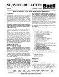
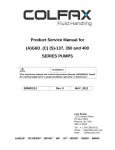
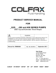
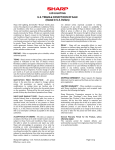
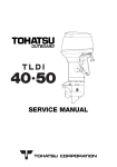
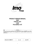
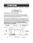
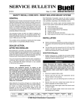
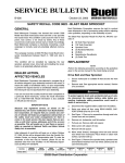
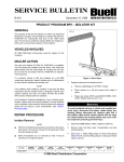
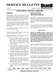
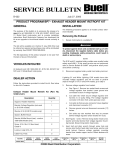
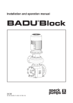
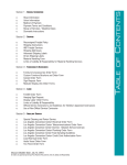
5
SERVICE BULLETIN
B-033A
December 4, 2000
SAFETY RECALL CODE 0820 - NEW SHOCK ABSORBER
GENERAL
Buell Motorcycle Company has learned that certain 1999 and
2000 Buell motorcycles were built with a rear shock absorber
that could break. If the shock should break, the underside of
the vehicle could drag on the ground, which may adversely
affect handling and could cause an accident. Accordingly,
Buell Motorcycle Company is voluntarily conducting a recall
campaign to formally recall all potentially affected motorcycles.
This campaign involves all 1999 M2 Cyclone and all 2000 X1
Lightning, M2 Cyclone, S3 Thunderbolt and S3T Thunderbolt
model Buell motorcycles manufactured between January 5,
1998 and May 31, 2000.
This condition was initially remedied by installing a shock
reinforcement package (SRP) on all potentially affected vehicles.
Since the release of the original bulletin (B-033), Buell Motorcycle Company has released a new shock absorber that provides the same benefits as the original SRP kit. This new
shock absorber installation should be performed in lieu of the
SRP installation on all affected models, once you have used
up your stock of SRP kits. This revised recall procedure
applies to affected motorcycles that did not have the initial
0820 recall service performed. For motorcycles that have
had the original 0820 recall service performed, obtain a factory authorization to replace the shock.
DEALER ACTION,
AFFECTED VEHICLES
Recently, Buell Distribution Corporation sent a complete list of
all vehicles shipped to your dealership involved in this recall. To
ensure the safety of all affected riders, it is your responsibility
to perform the required service on all affected vehicles, even if
the motorcycle was not purchased from your dealership.
If you are not sure that a safety recall has been completed on
a particular Buell motorcycle, contact the recall information
line at 1-800-448-1708. Recall information is also available
on TALON and hd-net.com.
IMPORTANT NOTE
Because only registered owners received notification
from Buell Distribution Corporation, we request that you
contact any owners of vehicles previously listed as
unregistered. Advise them of the safety recall and make
arrangements for them to come in for recall service. We
also require that you provide us with their names,
addresses and V.I.N.s as soon as possible. This will
enable us to mail them an owner’s letter as required by
National Traffic and Motor Vehicle Safety Act, as
amended.
ROUTING
SERVICE
MANAGER
SALES
MANAGER
PARTS
MANAGER
LEAD
TECHNICIAN
Kits must be ordered as required and will be available on or
before December 18, 2000. Use inventory of original recall
kits until exhausted. Once exhausted, the original kits will
supersede to the revised kits listed in this bulletin. To order
kits please fill out the attached order form and send/fax it to
the Warranty Department at (FAX) 414-343-8346. All kits will
be shipped, no charge, transportation paid.
Buell Distribution Corporation reserves the right to conduct
wave shipments in lieu of processing orders and/or adjusting
order quantities, depending on the availability of parts.
The revised 0820 Recall Kit (see below for correct Part Number) consists of:
Customer Instructions for Shock Replacement and
Adjustment
Shock Absorber
●
●
Clamp (for shock reservoir to bracket)
●
Clamp (for shock reservoir to oil return line)
Washer, 1/4 in (for reservoir clamp)
●
●
(2) Locknuts, Nylon (shock mounting)
Reservoir Mount Block
●
●
Front Shock Mount
(2) Front Shock Mount Bolts
●
●
(2) Locknuts, Metal (for front shock mount)
(3) Washers (for front shock mount)
●
●
New X1 Chin Fairing Bracket
●
Wellnut
Star Washer, 3/8 in. (1997 M2, S3/S3T only - front
●
shock mount) (not used)
●
Star Washer 1/4 in. (1997 M2, S3/S3T only - voltage
regulator bracket) (not used)
●
(2) Exhaust Port Gaskets (not used)
Screw (for voltage regulator bracket)
●
●
New Header Tie bar Spacer (not used)
The new shock recall kit is different depending on the motorcycle model. See below for the correct recall kit part numbers:
●
X1/M2: Part No. 94017Y
S3/S3T: Part No. 94018Y
REMOVAL
All Models
NOTE
Perform the following procedures according to the guidelines
given in the service manual for the model being serviced.
1.
Lift rear wheel off ground using REAR WHEEL SUPPORT STAND (Part No. B-41174). Secure front wheel of
motorcycle in a suitable lift.
TECHNICIAN
NO. 1
TECHNICIAN
NO. 2
TECHNICIAN
NO. 3
INITIAL HERE
©2000 Buell Distribution Corporation
TECHNICIAN
NO. 4
RETURN
THIS TO:
1WARNING
b0887x2x
To protect against shock and accidental start-up of vehicle, disconnect the negative battery cable before proceeding. Inadequate safety precautions could result in
death or serious injury.
2.
Disconnect negative battery cable.
3.
X1 Models Only: Remove chin fairing. See Section 2 of
X1 Service Manual for procedure. Discard wellnut.
4.
See Figure 1. Place a suitable jack under the swing arm
mount block and raise until crankcase is supported by
jack.
Flat Spot Under
Mount Block
Swingarm
NOTE
Steps 5-6 do not apply to M2 Cyclone models with original
equipment shocks that were not equipped with a remote reservoir.
5.
See Figure 2. Use a flex socket and extension to remove
locknut and washer from front reservoir clamp. Discard
clamp and locknut. Retain washer.
6.
See Figure 2. Loosen rear reservoir clamp. Slide reservoir and mount block out of clamp. Remove and discard
clamp and mount block.
7.
Remove allen screw and locknut (metric) from front of
shock and front shock mount. Discard locknut.
8.
Remove allen screw, washers and locknut (metric) from
rear of shock and swingarm while supporting shock
absorber. Discard locknut. Retain washers for re-use.
9.
Remove and discard shock absorber assembly.
Muffler
Jack
Figure 1. Jack Location on Mount Block
(Shock Removed for Clarity)
b0918x2x
*Nylon
Locknut (2)
*Reservoir Mount Block
*Rear Reservoir Clamp
Washers (2)
*Front Reservoir
Clamp
* Metal Locknut (2)
*Washers (3)
10. Remove two screws, washers and voltage regulator from
bracket.
11. Remove small button head screw and metal locknut (if
present) that secures voltage regulator bracket to front
shock mount. Leave bracket in place. Discard screw and
metal locknut.
NOTE
Model Year 1999 motorcycles have unthreaded front shock
mounts that require the use of washers and metal locknuts to
secure the front shock mount to the crankcase. Model Year
2000 front shock mounts were threaded and no locknuts
were used. The new front shock mount is not threaded and
will require the use of the new mounting hardware which
includes washers and metal locknuts.
12. Remove top and bottom front shock mount bolts (and
washers and locknuts if present). Remove and discard
front shock mount. Discard bolts, locknuts and washers.
*Front
Shock
Mount
30-33 ft-lbs
(41-45 Nm)
40-45 ft-lbs
(54.2-61 Nm)
* Included in Kit
Figure 2. New Shock Absorber Assembly
b0850x2x
Oil Feed Line
*Rear Reservoir
Clamp
*Front Reservoir
Clamp
INSTALLATION
IMPORTANT NOTE
The new front shock mount MUST be used with the new
shock absorber. The new shock is 1.77 in. (45 mm)
shorter than the previous shocks and requires the new
front mount to align and install properly.
See Figure 2. Install new front shock mount to crankcase
with two new front shock mount bolts, washers and
metal locknuts. Tighten bolts to 30-33 ft-lbs (41-45 Nm).
NOTE: Top bolt goes in from the left side, bottom bolt
goes in from right side. The bottom bolt does not use
washer under the bolt head.
2 of 5
Reservoir
1.
* Included in Kit
* Chin Fairing
Mount (X1 Only)
Figure 3. Reservoir Clamps (X1 Model Shown)
B-033A
2.
3.
Apply LOCITITE THREADLOCKER 243 (Blue) to
threads of new button head fastener. Attach voltage regulator bracket to front shock mount with small button
head fastener. Tighten fastener to 5-6 ft-lbs (7-8 Nm).
b0852x2x
Apply LOCTITE THREADLOCKER 243 (Blue) to threads
of voltage regulator screws. Install voltage regulator to
bracket with two screws and washers. Tighten fasteners
to 9-11 ft-lbs (12-15 Nm).
NOTE
All new shock absorbers, including those on M2 Models have
remote reservoirs that enable rebound damping adjustment.
4.
5.
Preload Measurement
(Rider Seated on Motorcycle)
See Figure 2. Position new shock absorber from kit in
mounting position.
All Models: 15.2-15.5 in. (386-394 mm)
Loosely install bolt, washers and new locknut through
rear shock eye and swing arm.
6.
X1 Models Only: Position new chin fairing bracket in
mounting position on front shock eye.
7.
Loosely install bolt and new locknut through front shock
eye and front shock mount (and X1 chin fairing bracket if
applicable).
8.
Position front clamp over reservoir. Loosely install new
front reservoir clamp to front shock mount with new
washer and new nylon locknut.
9.
See Figure 3. Loosely install new rear clamp around reservoir and oil feed line.
Figure 4. Measuring Preload
b00851x2x
10. All Models: Install new reservoir mount block between
oil pump fitting and remote reservoir.
Locknut
65-72 ft-lbs
(88-98 Nm)
11. Tighten front shock mounting hardware to 40-45 ft-lbs
(54.2-61.0 Nm). Tighten rear shock mounting hardware
to 30-33 ft-lbs (41-45 Nm).
12. Tighten clamps around reservoir.
Compression
Adjuster Slotted
Dial
Preload Adjuster
Figure 5. Preload and Compression Damping Adjustment
13. X1 Models Only: Install chin fairing using new wellnut.
See Section 2 of X1 Service Manual for procedure.
NOTE:
b0854x2x
If installing new swing arm from #0816 recall, stop procedure
here and see ADJUSTMENT on following page when swing
arm installation is complete. If not installing new swing arm,
continue with Step 14 below.
14. Lower and remove jack from under swing arm mount
block.
15. Connect negative battery cable. Tighten to 40 in-lbs (4.5
Nm).
Rebound Adjuster
Slotted Dial
16. Set preload. See ADJUSTMENT.
17. Test ride.
Figure 6. Rebound Adjustment
ADJUSTMENT
1.
NOTE:
See Figure 4. Check and adjust rear shock preload.
a.
With rider seated on motorcycle, the preload is
determined by measuring the distance between the
centers of the front and rear shock eye and adjusting until the measurement is within specification.
b.
See below for optimum preload measurements:
●
All Models: 15.2-15.5 in. (386-394 mm)
B-033A
●
All measurements must be taken with rider seated on
motorcycle.
●
Riders with passenger at or near GVWR may exceed
optimum preload adjustment.
3 of 5
2.
3.
4.
See Figure 5. To adjust shock preload, loosen the locknut and turn the preload adjuster at the end of the shock
to move can towards front or rear of motorcycle.
a.
Tighten adjuster (move can towards rear of motorcycle) to increase preload.
b.
Loosen adjuster (move can towards front of motorcycle) to decrease preload.
See Figure 7. When finished, apply wheel bearing
grease halfway around the shock (180 degrees) to the
mating faces of the locknut and adjuster nut and the first
few threads on the aluminum body leading to the
adjuster nut.
Thread locknut back into place.
NOTE
Torque wrench and crow’s foot must be set at 90 degrees to
prevent torque multiplication by wrench.
TOP VIEW
b0921x2x
Rear of Motorcycle
Locknut
Grease
Adjusting
Nut
Apply grease to shaded areas (halfway around shock)
to mating faces of nuts and to leading threads.
Figure 7. Locknut Tightening Procedure
5.
Using SHOCK PRELOAD ADJUSTING TOOLS (Part
No. B-45110), hold adjusting nut in place with 60 mm
ADJUSTING NUT WRENCH and tighten locknut to 6572 ft-lbs (88-98 Nm) with 52 mm LOCKNUT CROW’S
FOOT set at 90 degrees to the torque wrench.
6.
Wipe excess grease off of shock absorber.
NOTE
●
See Figures 5 and 6. To adjust rear shock to maximum
damping setting, use screwdriver to turn slotted dial on
appropriate adjuster clockwise until it stops. This is the
maximum damping setting.
●
See Figures 5 and 6. To adjust rear shock to factory recommended settings, turn dial counterclockwise from
maximum damping the amounts shown in Steps 7 and 8
to align the reference marks.
7.
See Figure 5. Set compression damping using the slotted dial on the shaft at the rear of the shock. New factory
setting is as listed below:
8.
●
M2/X1 Models: full damping minus 2.25 turns.
●
S3/S3T Models: full damping minus 2.5 turns.
See Figure 6. Set rebound damping using the slotted dial
on the remote reservoir at the front of the shock. New
factory setting is as listed below:
●
M2/X1 Models: full damping minus 1.5 turns.
●
S3/S3T Models: full damping minus 1 turn.
NOTE
When preload is increased, both compression and rebound
damping should be increased. If preload is decreased, both
compression and rebound damping should be decreased.
9.
Test ride motorcycle.
10. Provide customer with Customer Instructions for Shock
Replacement and Adjustment (Instruction Sheet Number
-J01561) provided in kit.
4 of 5
B-033A
CREDIT PROCEDURE
For each vehicle serviced, place a “C” in the letter box on the
Buell Dealer Service Card. Send the properly completed
dealer service cards to Buell Distribution Corporation, 3700
W. Juneau Ave., Milwaukee, WI 53208. Upon receipt and processing of your properly completed dealer service cards, you
will be credited for 0.6 hours labor for M2, S3 and S3T Models and 0.7 hours labor for X1 Models. All times include 0.1
hour administrative time. No credit will be issued for the kits
as they were sent no charge, transportation paid.
CREDIT PROCEDURES DEALER STOCK PARTS
Remove all affected shock absorbers (Part Nos. listed below)
from your inventory. To receive credit, complete a regular warranty claim referencing Service Bulletin B-033A in the
“Description of Repair” section. Fill in the rest of the claim as
follows.
Credit for Parts
Claim Type
Event 1,
Problem Part No.
Part Description
Event 2,
Problem Part No.
Part Description
BDS
93925Y or 54620-99Y
M2 Recall or OE Shock
Absorber
93930Y or 54622-99Y
S3/S3T Recall or OE Shock
Absorber
Event 3,
Problem Part No.
54621-99Y
Part Description
X1 OE Shock Absorber
Customer Concern
Code
9205
Condition Code
9111
NOTE
“Quantity” and part numbers may vary depending upon what
you have in stock.
Upon receipt of properly completed claim for parts in dealer
stock, you will receive the appropriate credit for parts. Buell
Distribution Corporation will advise at a later date how to
order updated shock absorbers to replenish your stock. Do
not order the recall kits to restock your inventory!
B-033A
5 of 5
QUANTITY
CITY/STATE/ZIP
ADDRESS
NAME
94018Y
S3/S3T
94017Y
X1/M2
F-1040
VEHICLE
IDENTIFICATION
NUMBER
D-W
FRT.
ACCT.
ACCT.
111-632.3
111-632.3
FOR OFFICE USE ONLY
WARRANTY CLAIM NO.
ORDER
TYPE
DEALER
NO.
ORDER
DATE
DEALER
ORDER
ALL ORDERS SUBJECT TO ACCEPTANCE AT MILWAUKEE, WI 53201
820
0
DE
O
C
Y
T
N
A
R
R
WA
from time to time, as liquidated damages for loss of sale. Purchaser will be responsible for collection and payment of all Federal, State and local taxes that apply on the retail sales.
of shipment, and in case of reconsignment or return of goods to seller, purchaser shall pay the entire cost connected therewith, plus zero, ten or twenty-five percent of selling price, as determined by Company policy
accepted order and seller shall not be liable for any loss or damage due to delay in shipment or failure to deliver. Any request for cancellation of this order or any part thereof must be received by seller prior to the date
Wisconsin or other point of origin. If accepted, this order as accepted shall be subject to availability of goods to seller for delivery to purchaser. Any delay in shipment shall not relieve purchaser of responsibility for his
PRINTED
IN U.S.A
PLEASE USE PART NUMBERS
DO NOT USE FOR
CORRESPONDENCE
NOTE: All orders subject to approval. You may not receive the total quantity of
kits ordered, due to parts a availability. If this happens, please submit another
ordered for the balance.
SAME
REGULAR
POLICE
DOWN VEHICLE
WARRANTY
ORDER TYPE
CITY/STATE/ZIP
ADDRESS
NAME
Code 0820: SHOCK
T
O
S
H
I
P
D
W
R
P
TYPE
CODE
All goods covered by this order, including goods back-ordered, will be billed at prices current at the time of shipment. Goods are purchased for resale and delivery is made to purchaser F.O.B. factory, Milwaukee,
PART NUMBER
PLEASE USE PART NUMBERS
DO NOT USE FOR
CORRESPONDENCE
T
O
S
O
L
D
B-033A
PARTS & ACCESSORY ORDER
P.O. BOX 594, MILWAUKEE, WI U.S.A 53201
BUELL DISTRIBUTION CORPORATION