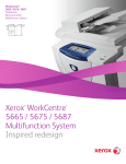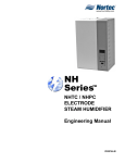
1
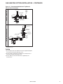
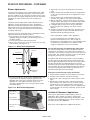
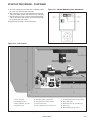
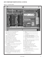
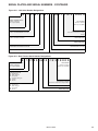
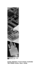
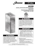
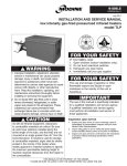
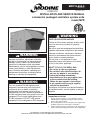
UNIT COMPONENT IDENTIFICATION / LOCATION
Figure 16.1 - Blower/Evaporator/Filter/Damper Sections
Figure 16.2 - Condenser Section
1
2
13
4
5
1
10
8
11
15
16
9
3
2
14
12
17
6
5
6
3
18
25
19
7
21
23
4
20
24
22
1 (O) GFCI convenience outlet
1 (S) Condenser fan housing
2 (S) Blower door switch
2 (S) Condenser fan motors
3 (S) Airflow proving switch
3 (S) Refrigerant filter/dryer assembly
4 (S) Supply fan motor
4 (S) Liquid line pressure transducer
5 (O) Hot gas reheat circuit shut-off valve (one additional located
in controls compartment)
5 (S) P
F™ aluminum microchannel condenser
coils
6 (S) Electronic expansion valve
6 (S) Schraeder valve pressure test port
7 (S) Refrigeration circuit sight glass
8 (O) Hot gas reheat coil
9 (S) Distributor and distributor piping (not all distributor tubes shown)
10 (S) High capacity evaporator coil
11 (O) 4" secondary filters, MERV 13 or 16
12 (S) 2" primary filters, MERV 10 (standard), 13, or 15
13 (O) Dirty filter pressure switch
14 (S/O) Outside air damper (standard on units with outside air)
15 (S/O) M
odulating damper actuator (standard on units with
outside air)
16 (O) Air velocity probe
17 (S) Outside air enthalpy sensor
18 (O) Return air damper
19 (O) Modulating damper actuator
20 (O) Return air enthalpy sensor
21 (O) Return air smoke detector
22 (S) Evaporator drain pan drain connection
23 (O) Gas or electric heat module (gas shown)
24 (O) Gas heating high limit control (standard if gas heat)
25 (O) Gas heating power exhauster outlet (standard if gas heat)
(S) = standard (O) = optional
16
MCP15-500.0
(S) = standard (O) = optional