1
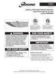
MCP15-500.0
5H0816400000
September, 2011
installation and service manual
commercial packaged ventilation system units
model MPR
WARNING
Improper installation, adjustment, alteration,
service or maintenance can cause property
damage, injury or death, and could cause
exposure to substances which have been
determined by various state agencies to cause
cancer, birth defects or other reproductive
harm. Read the installation, operating and
maintenance instructions thoroughly before
installing or servicing this equipment.
WARNING
This unit contains R-410A high pressure
refrigerant. Hazards exist that could result
in personal injury or death. Installation,
maintenance, and service should only be
performed by an HVAC technician qualified in
R-410A refrigerant and using proper tools and
equipment. Due to much higher pressure of
R-410A refrigerant, DO NOT USE service
equipment or tools designed for R22 refrigerant.
WARNING
FIRE OR EXPLOSION HAZARD
Failure to follow safety warnings exactly could
result in serious injury, death or property
damage.
Be sure to read and understand the installation,
operation and service instructions in this manual.
Improper installation, adjustment, alteration,
service or maintenance can cause serious
injury, death or property damage.
Do not store or use gasoline or other
flammable vapors and liquids in the vicinity
of this or any other appliance.
WHAT TO DO IF YOU SMELL GAS:
• Do not try to light any appliance.
• Do not touch any electrical switch, do
not use any phone in your building.
• Leave the building immediately.
• Immediately call your gas supplier from
a phone remote from the building.
Follow the gas supplier’s instructions.
• If you cannot reach your gas supplier,
call the fire department.
Installation and service must be performed by
a qualified installer, service agency or the gas
supplier.
Inspection on Arrival
1. Inspect unit upon arrival. In case of damage, report it
immediately to transportation company and your local
factory sales representative.
2. Check rating plate on unit to verify that power supply meets
available electric power at the point of installation.
3. Inspect unit upon arrival for conformance with description of
product ordered (including specifications where applicable).
THIS MANUAL IS THE PROPERTY OF THE OWNER.
PLEASE BE SURE TO LEAVE IT WITH the owner WHEN YOU LEAVE THE JOB.
special precautions / table of contents
Special Precautions
THE INSTALLATION AND MAINTENANCE INSTRUCTIONS IN
THIS MANUAL MUST BE FOLLOWED TO PROVIDE SAFE,
EFFICIENT AND TROUBLE-FREE OPERATION. iN ADDITION,
PARTICULAR CARE MUST BE EXERCISED REGARDING
THE SPECIAL PRECAUTIONS LISTED BELOW. FAILURE
TO PROPERLY ADDRESS THESE CRITICAL AREAS COULD
RESULT IN PROPERTY DAMAGE OR LOSS, PERSONAL
INJURY, OR DEATH. THESE INSTRUCTIONS ARE SUBJECT
TO ANY MORE RESTRICTIVE LOCAL OR NATIONAL CODES.
HAZARD INTENSITY LEVELS
1. DANGER: Indicates an imminently hazardous situation
which, if not avoided, WILL result in death or serious injury.
2. WARNING: Indicates a potentially hazardous situation
which, if not avoided, COULD result in death or serious injury.
3. CAUTION: Indicates a potentially hazardous situation
which, if not avoided, MAY result in minor or moderate injury.
4. Important: Indicates a situation which, if not avoided,
MAY result in a potential safety concern.
1. Appliances are designed for outdoor installation only.
DO NOT LOCATE APPLIANCES INDOORS.
2. The unit must be operated with a condensate trap.
Failure to install a condensate drain trap may result in
condensate overflowing from the drain pan, causing
damage to the unit and building.
3. Purging of air from gas lines should be performed as
described in ANSI Z223.1 - latest edition “National Fuel
Gas Code”, or in Canada in CAN/CGA-B149 codes.
4. Ensure that the supply voltage to the appliance, as indicated
on the serial plate, is not 5% less than the rated voltage.
5. Do not overcharge the refrigeration system. This can lead
to elevated compressor discharge pressure and possibly
flooding the compressor with liquid.
6. Do not reuse any mechanical or electrical component
which has been wet. Such component must be replaced.
important
danger
Appliances must not be installed where they may be exposed
to a potentially explosive or flammable atmosphere.
warning
1. All field gas piping must be pressure/leak tested prior to
operation. Never use an open flame. Use a soap solution or
equivalent for testing.
2. Gas pressure to appliance controls must never exceed
14" W.C. (1/2 psi).
3. Disconnect power supply before making wiring connections
to prevent electrical shock and equipment damage.
4. All appliances must be wired strictly in accordance with
the wiring diagram furnished with the appliance. Any
wiring different from the wiring diagram could result in a
hazard to persons and property.
5. Any original factory wiring that requires replacement must
be replaced with wiring material having a temperature
rating of at least 105°C.
6. To reduce the opportunity for condensation, the minimum
sea level input to the appliance, as indicated on the serial
plate, must not be less than 5% below the rated input, or
5% below the minimum rated input of dual rated units.
7. Ensure that the supply voltage to the appliance, as indicated
on the serial plate, is not 5% greater than the rated voltage.
8.When the dead front disconnect switch is in the “OFF”
position, supply power remains energized at top of
the dead front disconnect switch. The switch body is
located inside of another junction box to protect against
contact with the live wiring. The junction box must not
be disassembled unless the main power supply from the
building to the unit is de-energized.
9. This unit contains R-410A high pressure refrigerant.
Hazards exist that could result in personal injury or death.
Installation, maintenance, and service should only be
performed by an HVAC technician qualified in R-410A
refrigerant and using proper tools and equipment. Due
to much higher pressure of R-410A refrigerant, DO
NOT USE service equipment or tools designed for R22
refrigerant.
10.When servicing or repairing this equipment, use only
factory-approved service replacement parts. A complete
replacement parts list may be obtained by contacting
Modine Manufacturing Company. Refer to the rating plate
on the appliance for complete appliance model number,
serial number, and company address. Any substitution of
parts or controls not approved by the factory will be at the
owner's risk.
2
caution
1. To prevent premature heat exchanger failure, do not locate
ANY gas-fired appliances in areas where corrosive vapors
(i.e. chlorinated, halogenated or acid) are present in the
atmosphere.
2. To prevent premature heat exchanger failure, the input to
the appliance, as indicated on the serial plate, must not
exceed the rated input by more than 5%.
3.To prevent premature heat exchanger failure, observe
heat exchanger tubes by looking at the heat exchanger through the field installed access openings in connecting ductwork. If the tubes become red while blower and duct
furnace are in operation, check to be sure the blower has
been set to deliver the proper airflow for the application.
Refer to page 11 for Blower Adjustments.
4. Start-up and adjustment procedures should be performed
by a qualified service agency.
5. All refrigeration checks must be made by a qualified
R-410A refrigeration technician.
6. Do not release refrigerant to the atmosphere. When
adding or removing refrigerant, all national, state/province,
and local laws must be followed.
7. To check most of the Possible Remedies in the
troubleshooting guide listed in Table 22.1, refer to the
applicable sections of the manual.
Table of Contents
Inspection on Arrival............................................................. 1
Special Precautions.............................................................. 2
SI (Metric) Conversion Factors............................................ 3
Unit Location........................................................................ 3
Combustible Material and Service Clearances............. 3
Roof Curb/Duct Installation............................................ 4
Rigging Instructions/Unit Installation............................. 5
Unit/Condensate Drain Installation................................ 5
Electrical Connections................................................... 6
Gas Connections/Venting...........................................8-9
Start-Up Procedure............................................................ 10
General........................................................................ 10
Blower Adjustments..................................................... 11
Checking Refrigerant Charge...................................... 12
Gas Heating Option................................................14-15
Unit Features/Options Location Drawings.....................16-17
Dimensions/Weights . ...................................................18-20
Maintenance....................................................................... 21
Service & Troubleshooting............................................22-23
Serial Plates and Serial Numbers.................................24-25
Model Nomenclature.......................................................... 27
Commercial Warranty........................................... Back Page
MCP15-500.0
si (metric) conversion factors / unit location
SI (Metric) Conversion Factors
Table 3.1
To Convert Multiply By To Obtain
"W.C.
0.24
kPa
psig
6.893
kPa
°F
(°F-32) x 0.555
°C
inches
25.4
mm
feet
0.305
meters
CFM
0.028
m3/min
To Convert Multiply By To Obtain
CFH
1.699
m3/min
Btu/ft3
0.0374
mJ/m3
pound
0.453
kg
Btu/hr
0.000293
kW/hr
gallons
3.785
liters
psig
27.7
"W.C.
5. Be sure that the minimum clearances to combustible
materials and recommended service clearances are
maintained. For units with the gas heating option, be sure
clearances are maintained to the combustion air inlet louvers
and power exhauster discharge cover. Units are designed
for installation on non-combustible surfaces with the
minimum clearances shown in Figure 3.1.
Figure 3.1 - Combustible Material & Service Clearances
36.00
Unit Location
danger
SEE NOTE 2
Appliances must not be installed where they may be
exposed to potentially explosive or flammable atmosphere.
48.00
SEE NOTE 1
36.00
caution
Appliances are designed for outdoor installation only.
DO NOT LOCATE APPLIANCES INDOORS.
FOR UNITS WITH GAS
HEATING, MAINTAIN 12"
MINIMUM CLEARANCE TO
COMBUSTIBLES FROM
VENT TERMINATIONS
important
To prevent premature heat exchanger failure, do not locate
ANY gas-fired appliances in areas where corrosive vapors (i.e.
chlorinated, halogenated or acid) are present in the atmosphere.
Location Recommendations
1. When locating the packaged rooftop unit, Model MPR, consider
general space and cooling/heating requirements and availability
of gas and electrical supply.
2. Be sure the structural support at the unit location site is
adequate to support the weight of the unit and any other
required support structure. For proper operation the unit
must be installed in a level horizontal position.
3, All mechanical equipment generates some sound and
vibration that may require attenuation. Locating the
equipment away from the critical area is desirable within
ducting limitations. Frequently, units can be located above
utility areas, corridors, restrooms, and other non-critical
areas. Generally, a unit should be located within 15 feet of
a primary support beam. Smaller defections mean lesser
vibration and noise transmission. For critical applications,
please consult with an acoustical attenuation expert.
4. Do not install units in locations where the flue products
(if equipped with a gas fired heating option) can be drawn
into the adjacent building openings such as windows, fresh
air intakes, etc.
48.00
SEE NOTE 3
ACCESSORY
RAINHOOD
ADDITIONAL CLEARANCES:
-CLEARANCE ABOVE UNIT MUST BE UNOBSTRUCTED.
-CLEARANCE TO COMBUSTIBLES BELOW THE UNIT IS 6" MINIMUM.
➀ The minimum required clearance for service/maintenance is 48". If the ability
for future condenser coil replacement is desired, the minimum clearance must
be 112". See Note 2 for alternate coil replacement direction.
➁ The minimum required clearance for service/maintenance is 36". If the ability
for future condenser coil replacement is desired, the minimum clearance must
be 112" from the end panel of the condenser section. See Note 1 for alternate
coil replacement direction.
➂ The minimum required clearance for service/maintenance is 48". If the ability
for future evaporator and/or hot gas reheat coil replacement is desired, the
minimum clearance must be 64".
6. On units that have fresh air openings, a method must be
provided to prevent water and debris from entering the unit
such as a rainhood, which is available as an accessory
from Modine. Where possible, install the unit so that the
inlet is not facing into the prevailing wind to prevent water
entrainment.
MCP15-500.0
3
ROOF CURB / DUCT INSTALLATION / RIGGING INSTRUCTIONS
Roof Curb Installation
Duct Installation
An optional roof curb is available to simplify site preparation
and raise the unit above roof water and snow level for
drainage. It can be installed in advance of the unit. The curb
is shipped knocked down with separate instructions (Literature
MCP15-590) for its assembly, flashing, and sealing with the
roof. The following are some general guidelines for roof curb
installed units:
1. The unit is designed to accept 90° flanged ductwork on both
the supply and return air openings. Refer to the roof curb
(Figure 20.1) or the unit base (Figure 19.1) dimensional
drawings to determine the location of the openings.
2. Acoustic duct liners are recommended on all internal supply
and return air ducts.
3. When ductwork is installed prior to unit arrival, flexible
connections should be included to make connections easier
and to simplify possible future service.
4. When a roof curb is used in conjunction with factory
supplied discharge and/or return air connectors, the
ductwork can be fastened to the connectors prior to the unit
installation. The connectors will accept 90° flanged ductwork
(see Figure 4.2).
1. The roof structure must be adequately designed to support
the live weight load of the unit and any other required
support structure. The roof curb should be supported at
points no greater than five feet apart. Additional truss
reinforcement should be provided, if necessary.
2. Roof curbs supplied by Modine are fabricated from 10
gauge galvanized steel and supplied knocked down for
assembly on the job site. The curb consists of two side
pieces, two end pieces, gasketing, four joiner angles, four
2x4 inch wood nailing strips, nuts, bolts, and washers.
3. Outside dimensions must be held when installing curb.
Top surface must be level and straight to insure weathertightness. If roof is pitched it will be necessary to construct
a sub-base on which to install the curb. All corners must be
square.
4. All dimensions are +1/8 inch.
Figure 4.2 - Discharge and/or Return Air Connectors
UNIT
BASE
90° FLANGED
DUCTWORK
(By Installer)
BEFORE UNIT
INSTALLATION
CAULK ALL MATING
SURFACES
(Caulk by installer)
5. Final electric and gas connections must be made after unit
is installed to allow for tolerance in setting of unit on curb.
For electrical power supply allow approximately eight feet
of wire, plus provisions for weathertight flexible conduit for
connection to unit, as required by local codes.
6. Maintain a 12-inch minimum height from top of roof deck to
top of curb.
7. Caulk butt joints after curb is assembled and installed on
roof structural members and roof flashing is added.
8. For improved sound attentuation, line the roof deck within
the curb area with 2" acoustic fiberglass.
ROOF
CURB
DISCHARGE AIR
CONNECTOR
5. To assure proper air flow from the unit, follow these duct
design recommendations:
a. Be sure ducts are properly sized and installed.
b. As a general rule, all discharge ducts should have a
straight run of at least three (3) hydraulic duct diameters
before making turns in the ductwork.
Figure 4.1 - Typical Curb Details
Curb Gasketing*
Counterflashing
(By Others)
Roofing
Material
(By Others)
Insulation
(By Others)
Cant Strip
(By Others)
2" Acoustic
Fiberglass
(By Others)
6" Inverted
Channel
Both Sides
(By Others)
*Available as a factory supplied, field installed accessory.
4
c. W
herever turns in the duct work is made, include turning
vanes.
d. Supply air ducts in a “T” configuration should be
avoided to prevent air temperature stratification. If this
configuration must be used, provide appropriate mixing
devices and/or the necessary straight duct length before
the “T” to provide uniformly mixed air temperature
delivery to both supply air duct trunks.
Utility Connections
Roof Insulation
(By Others)
Roof
Truss
Hydraulic Duct Diameter for Rectangular Ducts = 4A/P
Hydraulic Duct Diameter for Circular Ducts = D
where:
A = Cross Sectional Area of Rectangular Duct
P = Perimeter of Rectangular Duct
D = Diameter of Round Cut
2 x 4 Wooden
Nailing Strip*
Curb*
RETURN AIR
CONNECTOR
Utility and control connections can be made to the unit from the
bottom or through the fixed side panels. Holes can be made
in fixed side panels to accommodate utility connections as
specified according to the unit dimensional drawings. Sealing
of holes cut in the unit casing for utility connections should be
done with care to prevent air and water leaks.
Roof
Deck
MCP15-500.0
UNIT / CONDENSATE DRAIN INSTALLATION
Rigging Instructions
Four 1.5" eye bolts at the top of the unit in each corner are
supplied to facilitate lifting the unit. For either crane or helicopter
lift of the equipment to the rooftop, connect sturdy steel cables
or chains with eye loops as illustrated in Figure 5.1. For stability
in lifting and lowering and to prevent damage to the eye bolt
lifting points, include a spreader bar as illustrated in Figure 5.1.
Figure 5.1 - Typical Rooftop Furnace Rigging
ADJUST CHAIN
LENGTH SO UNIT
IS LEVEL WHEN
LIFTED
SPREADER BAR
AND LIFTING CHAINS
BY INSTALLER
(4) 1.50" LIFTING
EYE BOLTS
(EACH CORNER
OF UNIT)
APPROX.
75°
RAINHOOD
ACCESSORY
(FIELD INSTALL)
Unit Installation
Follow site preparation instructions for the roof curb before
installation. Check the Serial Plate(s) of unit with plans to be
sure unit is properly located (see pages 24 and 25). Although
units may look outwardly similar, their function, capacities,
options, and accessories will often vary. Check dimensions.
If unit is to be installed on a factory-supplied curb:
1. Install roof curb using instructions on page 4.
2. Thoroughly clean and dry the top of the curb surface.
3. Lay a bead of weather resistant caulking on top perimeter
of roof curb as illustrated in Figure 4.2.
4. Orient hoisted unit to its ductwork and set it down evenly
on curb.
5. Make final unit connections to the electric power supply
and remote control circuits. Connect the gas lines to the
unit heating compartment in accordance with the submittal
drawings and architect plans. Caulk all utility line clearance
holes on the unit after connections are completed.
1. The condensate drain pan includes a 1-1/4" female NPT
stainless steel connection accessible from the exterior of the
unit casing. Do not reduce the drain diameter.
2. The drain line should include unions for disconnecting the
line at or near the unit for maintenance/servicing of the unit.
The drain line must not interfere with access panels, which
are removable for maintenance/service.
3. The drain line must include a trap immediately after the unit,
as shown in Figure 5.2. Failure to do so will result in water
that cannot properly drain from the unit, eventually causing
the drain pan to fill and overflow. If the drain pan overflows,
significant damage can occur to the unit and/or building on
which the unit is installed. A drain pan float switch is included
as standard and will disable the unit if the maximum water
level is reached.
4. The design of the trap design is critical to ensure proper
drainage. If the trap is not constructed properly with the
dimensions as outlined in the following instructions, air could
be drawn through the drain pipe and into the system or could
back up into the drain pan.
• The drain is located on the suction side of the main
supply air fan, resulting in a negative pressure relative to
outside the unit cabinet. The trap height must be at least
6” to account for maximum negative pressure, including
allowance for dirty filters. Note that the trap height is the
difference in height from the drain connection of the unit to
the leaving side of the trap. Refer to Figure 5.2.
The trap depth must be ½ x the trap height. For example, if
the trap height is the minimum 6”, the trap depth must be 3”
(see Figure 5.2).
• For maintenance, it is recommended to have a capped
cleanout at the top of the trap as shown in Figure 5.2.
5. After the exit from the trap, the drain must be pitched
down from the unit connection at least 1” for every 10 feet
of horizontal run to promote proper drainage. If the local
installation code allows, the drain can be run to a waste
water system.
6. If the trap may experience below freezing temperatures
during non-cooling periods, precautions must be taken to
avoid water from freezing in and damaging the trap and drain
system. Examples include freeze plugs, heating wraps, etc.
7. The trap must be primed before the unit is put into operation
and properly maintained on a regular schedule. Refer to the
Startup Procedure section and the Maintenance section for
additional guidance.
Figure 5.2 - Condensate Drain Trap Installation
TRAP HEIGHT
(6" MINIMUM)
Condensate Drain Trap Installation
CAPPED
CLEANOUT
caution
The unit must be operated with a condensate trap. Failure
to install a condensate drain trap may result in condensate
overflowing from the drain pan, causing damage to the unit
and building.
1/2 x TRAP
HEIGHT
All units require a drain system to be connected to the
condensate drain pan connection which is accessible from the
exterior of the unit casing. See Figure 16.1 for location. The
drain system is to be installed as follows:
MCP15-500.0
5
ELECTRICAL CONNECTIONS
Electrical Connections
warning
1. Disconnect power supply before making wiring connections to prevent electrical shock and equipment damage.
2. All appliances must be wired strictly in accordance with the wiring diagram furnished with the appliance. Any wiring different from the wiring diagram could result in a hazard to persons and property.
3. Any original factory wiring that requires replacement must be replaced with wiring material having a temperature rating of at least 105°C.
4. Ensure that the supply voltage to the appliance, as indicated on the serial plate, is not 5% greater than rated voltage.
caution
1. Ensure that the supply voltage to the appliance, as indicated on the serial plate, is not 5% less than the rated voltage.
1. Installation of wiring must conform with local building
codes, or in the absence of local codes, with the National
Electric Code ANSI/NFPA 70 - Latest Edition. Unit must
be electrically grounded in conformance to this code. In
Canada, wiring must comply with CSA C22.1, Part 1,
Electrical Code.
2. Two copies of the job specific wiring diagram are provided
with each unit, one permanently affixed to the inside of the
door of the controls compartment and the other as a loose
copy with the literature packet that ships with the unit. Refer
to this diagram for all wiring connections.
3. Control wiring consists of both 24V analog control wiring
and low current digital control signal wiring. To avoid
signal interference, the two types should either be run in
separate conduits, or if run in the same conduit, the digital
signal wiring should be shielded at one end of the wiring
run. Wiring should be twisted, stranded, and shielded
communication wire.
4. The wire gauge must be sized according to the National
Electric Code or CSA code based on amp draw and length
of run. Refer to Table 6.1 for maximum wire lengths and
the number of wires that can be wired to each low voltage
terminal block.
Table 6.1 - 24V and Digital Control Wire Lengths
6
Maximum Distance from
Control Device to Unit
Minimum
Recommended
Wire Gauge
24V Control Wiring
Digital Control Wiring
22
n/a
120
20
n/a
200
18
75
300
16
125
500
14
175
n/a
5. Depending on the configuration of the unit controls, there
are sensors that are field installed. Review the unit ordered
to verify the sensors supplied match the configuration of
the unit. The following are sensors that may be included for
field installation:
Supply Air Temperature Sensor
This sensor is required on all units and should be mounted
in the supply air ductwork downstream of the unit. The
sensor should be located at least 5 feet, but not more than
20 feet downstream from the unit discharge.
Space Temperature/Humidity Sensor
This sensor is required on all units that have space
temperature/humidity reset control. The sensor is to be
wall-mounted in the space at a height of approximately
5 feet from the floor.
Building Pressure Sensor
This sensor is required on all units that have space
pressure control, either through modulating dampers or
variable frequency drive control on the supply air blower.
The sensor is to be mounted inside a control panel in the
space and includes two pressure taps. One pressure tap is
for outside atmospheric pressure reference, the other is for
sampling the space pressure.
Space CO2 Sensor
This sensor is required on all units that have demand based
ventilation control. The sensor is to be mounted in the
space at a height of approximately 5 feet from the floor.
For further instructions on the above sensor(s), refer to the
installation instructions that shipped with the sensor(s).
6.Make sure all multi-voltage components (motors,
transformers, etc.) are wired in accordance with the power
supply voltage.
7.The power supply to the unit must be protected with a fused
or circuit breaker disconnect switch. Figure 17.1 shows the
location of the factory installed dead front disconnect option,
if provided. Field installed disconnect switches should be
mounted where required by the National Electric Code.
Refer to the Model Serial plate for MCA and MOP values
for the unit.
8.The power supply must be within 5% percent of the voltage
rating and each phase must be balanced within 2 percent of
each other. If not, advise the utility company.
9.External electrical service connections that must be
installed include:
a. Supply power (120, 208, 240, 480, or 600 volts).
b. Thermostats, building pressure sensors, or any other
accessory control devices that may be supplied (24 volts).
10.All outdoor electrical connections must be weatherized to
prevent moisture from entering the electrical compartment.
11.Electrical connections are made in the controls cabinet and
can be run through the bottom or side of the unit. Refer to
the dimensions on pages 18 and 19 for locations of wiring
entrance. Refer to the wiring diagram for the terminal
location of all low voltage wiring.
MCP15-500.0
PAGE INTENTIONALLY LEFT BLANK
MCP15-500.0
7
GAS HEATING OPTION installation
THE INSTRUCTIONS ON PAGES 8 AND 9 ARE APPLICABLE TO OPTIONAL
GAS HEATING (MODEL NOMENCLATURE DIGIT 17=2 OR 3).
IF THE UNIT DOES NOT HAVE THE GAS HEAT OPTION,
SKIP TO INSTRUCTIONS ON PAGE 10.
Gas Connections
warning
1. All field gas piping must be pressure/leak tested prior to
operation. Never use an open flame. Use a soap solution
or equivalent for testing.
2. Gas pressure to appliance controls must never exceed
14" W.C. (1/2 psi).
3. To reduce the opportunity for condensation, the minimum sea level input to the appliance, as indicated on the serial plate, must not be less than 5% below the rated input, or 5% below the minimum rated input of dual rated units.
caution
Purging of air from gas supply line should be performed as
described in ANSI Z223.1 - latest edition “National Fuel Gas
Code”, or in Canada in CAN/CGA-B149 codes.
important
To prevent premature heat exchanger failure, the input to the
appliance, as indicated on the serial plate, must not exceed
the rated input by more than 5%.
Note: For bottom piped units, some local codes may require a
manual shutoff valve external to the unit casing. In this case,
the gas piping must exit the unit through the side piping hole,
followed by the manual shut-off valve, piped back into the unit
corner post, through the unit bottom, and lead to an additional
union and manual shut-off valve.
4.Provide a sediment trap before each unit in the line where
low spots cannot be avoided (see Figure 9.1).
5.When Pressure/Leak testing, pressures above 14" W.C.
(1/2 psi), close the field installed shut-off valve, disconnect
the appliance and its combination gas control from the gas
supply line, and plug the supply line before testing. When
testing pressures 14" W.C. (1/2 psi) or below, close the
manual shut-off valve on the appliance before testing.
Table 8.1 - Natural Gas Heating Gas Consumption ➀
Furnace Size (Btu/hr)
Gas Consumption (CFH)
Orifice Drill Size
Orifice Quantity
J
300,000
286
2.2mm
7
Digit 18
K
400,000
381
#43
9
L
500,000
476
#39
9
➀U
nit consists of 2 furnaces, each rated 1/2 the value shown in Table 8.1. Values
shown are for both furnaces combined. Natural gas consumption based on a
heating value of 1050 Btu/cu. ft.
Table 8.2 - Gas Pipe Capacities (Cu. Ft. per Hour) ➁
Pipe
Gas Pipe Diameter
1.Installation of piping must conform with local building codes,
Length
1"
1-1/4"
1-1/2"
2"
or in the absence of local codes, with the National Fuel Gas
(feet)
Code, ANSI Z223.1 (NFPA 54) - Latest Edition. In Canada,
10
520
1050
1600
3050
installation must be in accordance with CAN/CGA-B149.1 for
20
350
730
1100
2100
natural gas units and CAN/CGA-B149.2 for propane units.
30
285
590
890
1650
40
245
500
760
1450
2.Piping to units should conform with local and national
50
215
440
670
1270
requirements for type and volume of gas handled, and
60
195
400
610
1150
pressure drop allowed in the line. Refer to Table 8.1 to
70
180
370
560
1050
determine the cubic feet per hour (cfh) for the size of unit
80
170
350
530
990
to be installed. Using this cfh value and the length of pipe
90
160
320
490
930
necessary, determine the pipe diameter from Table 8.2.
100
150
305
460
870
Where several units are served by the same main, the total
125
130
275
410
780
capacity, cfh and length of main must be considered. Do
150
120
250
380
710
not use pipe sizes smaller than 1". Table 8.2 allows for a
➁ Gas pipe capacities based on gas pressure up to 14" W.C. through Schedule
0.3" W.C. pressure drop in the supply pressure from the
40 pipe with a pressure drop of 0.3" W.C. for Natural gas with a specific gravity
building main to the unit. The inlet pressure to the unit must
of 0.60.
be 6-7" W.C. for natural gas. When sizing the inlet gas pipe
diameter, make sure that the unit supply pressure can be
met after the 0.3" W.C. has been subtracted. If the 0.3"
W.C. pressure drop is too high, refer to the Gas Engineer’s
Handbook for other gas pipe capacities.
3.The gas piping to the unit can enter the unit from the side
of the unit (refer to the unit Dimensions on page 18) or from
below (refer to the base Dimensions on page 19). A drill
locator sticker is located on the side of the unit to indicate
the safe area for drilling the hole for side gas pipe entry.
Install a ground joint union with brass seat and a manual
shut-off valve external of the unit casing, and adjacent to the
unit for emergency shut-off and easy servicing of controls,
including a 1/8" NPT plugged tapping accessible for test
gauge connection (see Figure 9.1). Verify the manual shutoff valve is gas tight on an annual basis.
8
MCP15-500.0
GAS HEATING OPTION installation - continued
Figure 9.1 - Recommended Sediment Trap/Manual
Shut-off Valve Installation
Side Gas Connection
GAS
SUPPLY LINE
MANUAL GAS ➀
SHUT-OFF VALVE
GROUND
JOINT
UNION
W/ BRASS
SEAT
GAS
SUPPLY LINE
TO
CONTROLS
PLUGGED
1/8" NPT TEST
GAGE CONNECTION
3"
MIN.
SEDIMENT
TRAP
Bottom Gas Connection
TO
CONTROLS
PLUGGED 1/8"
NPT TEST GAGE
CONNECTION
MANUAL GAS ➀
SHUT-OFF VALVE
GAS
SUPPLY LINE
Through hole
in bottom of unit.
(caulk hole to prevent
water leakage.)
GROUND
JOINT
UNION
W/ BRASS
SEAT
3"
MIN.
SEDIMENT
TRAP
➀M
anual gas shut-off valve is in the “OFF” position when handle is perpendicular to pipe.
Venting
1.Do not operate the units without the factory supplied (shipped
loose) power exhauster discharge cover.
2.Do not modify or obstruct the combustion air inlet louvers or
the power exhauster discharge cover.
3.Do not add any vents other than those supplied by the
manufacturer.
MCP15-500.0
9
start-up procedure
General
WARNING
WARNING
When the dead front disconnect switch is in the “OFF”
position, supply power remains energized at top of
the dead front disconnect switch. The switch body is
located inside of another junction box to protect against
contact with the live wiring. The junction box must not
be disassembled unless the main power supply from the
building to the unit is de-energized.
important
12.Turn on power to the unit at the disconnect switch.
Note: The unit includes a blower door switch that is factory
installed inside the blower section door on the access side
of the unit. When the blower section door is opened, the
switch is opened and interrupts power to the low voltage
circuit and de-energizes the motor starter that controls
blower motor operation.
13.Check the Carel microprocessor controller and supply fan
blower motor for electrical operation. If the unit is equipped
with the optional power exhauster, check the blower motor for
electrical operation. If these do not function, recheck the wiring
diagram. Check to insure that none of the Control Options have
tripped.
14.Check to make sure that the damper(s) open(s) properly
without binding.
1. To prevent premature heat exchanger failure, observe
heat exchanger tubes by looking at the heat exchanger through the field installed access openings in connecting ductwork. If the tubes become red while blower and duct
furnace are in operation, check to be sure the blower has
been set to deliver the proper airflow for the application.
Refer to page 11 for Blower Adjustments.
2. Start-up and adjustment procedures should be performed
by a qualified service agency.
1. Turn off power to the unit at the disconnect switch. Check that
fuses or circuit breakers are in place and sized correctly. If
equipped with gas heating option, turn all hand gas valves to
the “OFF” position.
Note: The dead front disconnect switch, if included, is
factory installed in the controls/compressor compartment
section. The disconnect switch is designed so that it
must be turned “OFF” before entry to the compartment
can be obtained. When in the “OFF” position, power
is disconnected to all unit wiring electrically following
the switch (see WARNING). For servicing the unit, the
disconnect switch can be manually overridden by using
a wrench and turning the disconnect switch shaft 90°
clockwise.
15.Check the blower wheel for proper direction of rotation when
compared to the air flow direction arrow on the blower housing.
Blower wheel rotation, not air movement, must be checked as
insufficient air will be delivered with the blower wheel running
backwards.
16.Check the blower speed (rpm). Refer to Blower Adjustments for
modification.
17.Check the motor speed (rpm).
18.Check the motor voltage. On three phase systems, check to
make sure all legs are in balance.
19.Check the motor amp draw to make sure it does not exceed
the motor nameplate rating. Check all legs to insure system is
balanced.
2. Open the controls compartment and blower access doors.
3. Check that the supply voltage matches the unit supply voltage
listed on the Unit Serial Plate. Verify that all wiring is secure
and properly protected. Trace circuits to insure that the unit has
been wired according to the wiring diagram.
4. Check that all electrical and gas connections are weatherized.
5. For units with gas heating, check to insure that the combustion
air inlet louvers and the power exhauster discharge cover is
free from obstructions.
6. Check to see that there are no obstructions to the intake and
discharge of the unit.
7. Check the belt tension and sheave alignment.
8. All bearings are permanently lubricated and do not require
lubrication.
9. Check to make sure that all filters are in place and that they are
installed properly according to direction of air flow.
10.Perform a visual inspection of the unit to make sure no damage
has occurred during installation.
11. Check that the evaporator drain pan drain trap has been
primed with water.
10
MCP15-500.0
Start-up Procedure - continued
Blower Adjustments
The units are designed for ease of airflow adjustments, within
certain limits, for field balancing against actual external static
pressure conditions. If the static pressure external to the unit is
above or below the original design point for the unit, the blower
will deliver an airflow volume that is lower or higher than
required.
The blower speed (supply and/or exhaust blowers) may be
adjusted to achieve the desired air volume, provided the
adjustment is within the temperature rise and static pressure
limits shown on the unit serial plate for both heating and
cooling. The motor amp draw should not exceed the motor
nameplate amp rating.
The motor sheave on the blower motor is adjustable to permit
adjustment of the blower speed as follows:
1. Turn off power to the unit at the disconnect switch. If
equipped with gas heat option, turn all hand gas valves to
the “OFF” position.
2. Loosen the belt tension and remove the belt.
3. On the motor sheave, loosen the set screw on the side away
from the motor (see Figure 11.1).
5. Tighten the set screw on the flat portion of the sheave
shaft.
6.Replace the belt and verify that the belts are aligned in the
sheave grooves properly and are not angled from sheave
to sheave.
7.Turn on power to the unit and initiate blower motor
operation. For guidance, refer to the Controls Manual.
8.With an amp meter, check the motor amps to ensure the
maximum motor amp rating is not exceeded. Verify airflow
volume and repeat steps above for further adjustment.
9.If equipped with gas heat, turn on the gas and initiate
burner operation. For guidance, refer to the Controls
Manual.
10.Verify the temperature rise listed on the serial plate of the
heating section has not been exceeded. Airflow can be
approximated with the following formula:
CFM = (Input Btu/hr x 0.80) / (1.08 x Temp Rise)
For low air temperature rise units (Digit 19=L), the
maximum air temperature rise is 75°F. For high air
temperature rise units (Digit 19=H) or units with Digit 19=N,
the maximum air temperature rise is 100°F. The final
supply air temperature must not exceed 130°F.
Figure 11.1 - Motor Sheave Adjustment
Air Flow Proving Switch and Optional Dirty Filter Switch
The air flow proving switch is factory installed in the blower
compartment. The purpose of the air flow proving switch is to
cut power to the controls if a positive pressure is not measured
by the switch. This could be caused by a lack of air movement
through the evaporator coil or heat exchanger.
Set Screw
Toward Motor
The optional dirty filter pressure switch is factory installed in
the filter section. The dirty filter pressure switch monitors the
pressure differential between the two sides of the filters. When
the filters become dirty, the differential pressure increases
and trips the pressure switch which initiates an alarm from the
Carel controller. The pressure differential switch must be field
set because setting the switch requires the blower to be in
operation and the ductwork to be installed.
Adjustable Half
of Sheave
Setting the Air Flow Proving or Dirty Filter Switch
1. Ensure that the unit filters are clean. Replace if necessary.
4. To increase the blower speed, turn the adjustable half of the
sheave inward. To decrease the blower speed, turn the
adjustable half of the sheave outward. The sheave half is
adjustable in ½ turn (180°) increments. Each ½ turn
represents approximately a 2-5% change in blower speed
and airflow volume.
Figure 11.2 - Belt Tension Adjustment
Motor Sheave
(adjustable)
Blower Sheave
(non-adjustable)
Automatic Belt
Tensioner
2.Using the Carel controller, start blower operation.
3. Turn the set screw of the pressure switch clockwise until it stops.
4. With the wires removed from the common and normally
open terminals of the switch, measure continuity and turn
the adjustment screw counter-clockwise until the switch
makes. Then turn the adjustment screw one additional turn
counter-clockwise to account for dirty filters or other system
static changes.
Variable Air Movement Applications
Units may be supplied with variable frequency drives for
applications where variable air volume is required. The
minimum air flow may be varied between 50 and 100% of the
full speed air flow depending on the controls selection of the
unit, but never less than 3000CFM.
Refer to the Controls Manual for additional information.
MCP15-500.0
11
Start-up Procedure - CONTINUED
Checking Refrigerant Charge
WARNING
caution
WARNING
This unit contains R-410A high pressure refrigerant.
Hazards exist that could result in personal injury or death.
Installation, maintenance, and service should only be
performed by an HVAC technician qualified in R-410A
refrigerant and using proper tools and equipment. Due to
much higher pressure of R-410A refrigerant, DO NOT USE
service equipment or tools designed for R22 refrigerant.
6.Determine if the system is undercharged or over charged
and correct as follows:
a. Undercharged: Typically, superheat is too high and subcooling is too low. Refrigerant should be added.
b. Overcharged: Typically, superheat is too low and subcooling is too high. Refrigerant should be removed.
7. After adding or removing refrigerant, allow the system to
stabilize for 10-15 minutes before making any other
adjustments.
8.Repeat the steps above until the sub-cooling and superheat
is within the range specified.
9.Once the correct charge has been established, operate the
unit reheat mode to verify correct operation.
Do not overcharge the refrigeration system. This can lead
to elevated compressor discharge pressure and possibly
flooding the compressor with liquid.
important
1. A
ll refrigeration checks must be made by a qualified
R-410A refrigeration technician.
2. Do not release refrigerant to the atmosphere. When
adding or removing refrigerant, all national, state/
province, and local laws must be followed.
Refrigerant charge can be verified by checking both superheat
and sub-cooling.
1.Verify proper air distribution across the evaporator coil face
area. Air flow should not vary by more than 20%.
2.From the Carel control, create a call for cooling. If the unit
has the hot gas reheat option, the hot gas reheat valves
must be closed.
3.The unit must be operated at near to full load operation
before checking the refrigerant charge. The unit operation
should be stabilized, typically after 10-15 minutes of
operation.
4. Measure sub-cooling as follows:
a. Read the gauge pressure at the liquid line test port (Item 6
in Figure 16.2). Note the saturation temperature on the
gauge.
b. Measure the temperature of the liquid line at a point near
where the pressure reading was taken.
c. Subtract the measured liquid line temperature from the
saturation temperature to determine the liquid sub-cooling.
For units without the hot gas reheat option, the subcooling should be 10-15°F. For units with the hot gas
reheat option, the sub-cooling should be 15-20°F.
5. Measure the superheat as follows:
a. Read the gauge pressure at the suction line close to the
compressor. Note the saturation temperature on the
gauge.
b. Measure the temperature of the suction line at a point
near where the pressure reading was taken.
c. Subtract the saturated temperature from the measured
suction line temperature to determine the evaporator
superheat. The superheat should be 8-12°F.
12
MCP15-500.0
PAGE INTENTIONALLY LEFT BLANK
MCP15-500.0
13
start-up procedure - CONTINUED
Gas Heating Option
Main Burner Adjustment
1.Check the ignition control and gas valve for electrical
operation.
The gas pressure regulator (integral to the combination gas
control) is adjusted at the factory for average gas conditions.
It is important that gas be supplied to the duct furnace in
accordance with the input rating on the serial plate. Actual
input should be checked and necessary adjustments made
after the duct furnace is installed. Over-firing, a result of too
high an input, reduces the life of the appliance and increases
maintenance. Under no circumstances should the input exceed
that shown on the serial plate.
Measuring the manifold pressure is done at the pressure tap
on the manifold tee. Refer to Figure 15.2 for location of the
pressure tap plug.
2.Recheck the gas supply pressure at the field installed
manual-shut-off valve. The inlet pressure should be 6"-7"
W.C. on natural gas but never more than 14" W.C. If inlet
pressure is too high, install an additional pressure regulator
upstream of the combination gas control.
3.Check the power exhauster speed control setting to ensure
it matches Table 14.1. Refer to Figure 15.2 for location of
Power Exhaust Speed Control Board.
Table 14.1 - Power Exhaust Speed Control Settings
Control Switch Setting
Furnace
Configuration
Digit
18
Digit
19
1
300MBH
J
N
ON
OFF OFF OFF ON ON
400MBH
(High ATR)
K
H
OFF
ON
400MBH
(Low ATR)
K
L
OFF OFF
ON
OFF ON ON
500MBH (All ATR)
L
H or L OFF OFF
ON
OFF ON ON
2
3
4
5
6
OFF OFF ON ON
4.Open the field installed manual gas shut-off valve and set
the combination gas control valve to the “ON” position for
one heat exchanger only.
5.Adjust the Carel control setpoint to create a call for heat.
Refer to the Controls Manual for instructions on changing
the setpoint.
6.Check to make sure that the main gas valve opens while
the supply fan blower is operating.
To Adjust the Manifold Pressure
1. M
ove the field installed manual shut-off valve to the “OFF”
position.
2. Remove the 1/8" pipe plug in the pipe tee of one furnace and
attach a water manometer of “U” tube type which is at least
12" high.
3. Move the field installed manual gas shut-off valve to the
“ON” position.
4. The EXA STAR modulating valve series has two buttons and
a communication LED for the user interface. The buttons
are used to set the valve for high and low fire settings
(see Figure 15.1). To adjust the high and low fire pressure
settings, remove the two screws holding the cover on each
valve and set as follows:
High Fire Setting
7.Check the gas pressure at the INLET to the combination
gas control valve and adjust as needed to maintain
6"-7" W.C. This pressure is required for proper ignition and
to attain the rated input of the unit. If this pressure cannot
be obtained the gas supply is undersized and needs to be
corrected or the gas supplier must be contacted.
8.Check gas pressure on the OUTLET of the combination gas
control valve when the burners are functioning. This should
be set to 4.0" W.C. Adjust the gas control valve regulator as
needed (see gas valve instruction sheet for location.)
9.Check to insure that gas controls sequence properly (see
Controls Manual). Verify if the unit has any additional
control devices and set according to the instructions in the
Control Options.
10.Repeat steps 3 through 8 for the 2nd heat exchanger.
11.Check operation of both heat exchangers. Verify that
burners do not go out as valves modulate to low fire. This is
most easily accomplished by entering the low fire program
mode on each modulating valve as described in the next
section.
12.Operate both heat exchangers at high fire and verify that
gas pressure to the INLET of the combination gas control
valve is maintained at 6"-7" W.C.
13.Turn off both heat exchangers. Verify that pressure at the
combination gas control valve INLET does not exceed
14" W.C. If pressure cannot be maintained at 6"-7" W.C.
while operating or if pressure exceeds 14" W.C. when
both heat exchangers are off, the gas supply system is
undersized and must be corrected.
1. To enter the high fire setting mode, press and hold button
#1 until the LED lights solid red, then release. The valve
is now in the high fire setting mode. Confirm that the
high fire manifold pressure is 3.5" W.C. and if necessary,
buttons #1 and #2 are used to set the desired high fire
setting. Press or hold Button #1 to increase gas flow.
Press or hold Button #2 to decrease gas flow. Each
button press equates to the minimum available step
size and will increase or decrease flow slowly. Holding
the button down auto steps and eliminates the need to
repeatedly press the button. Use this feature to rapidly
adjust the flow.
2.To save the high fire setting, simultaneously hold Buttons
#1 and #2 until the LED turns OFF. Note that controls
left in any setting mode will default to the current settings
and return to normal operating mode after 5 minutes of
inactivity.
Low Fire Setting
1. To enter the low fire setting mode, press and hold button
#2 until the LED light blinks red, then release. The valve
is now in the low fire setting mode. Confirm that the low
fire manifold pressure is 0.3" W.C. and if necessary,
buttons #1 and #2 are used to set the desired low fire
setting. Press or hold Button #2 to decrease gas flow.
Each button press equates to the minimum available step
size and will increase or decrease flow slowly. Holding
the button down auto steps and eliminates the need to
repeatedly press the button. Use this feature to rapidly
adjust the flow.
2.To save the low fire setting, simultaneously hold Buttons
#1 and #2 until the LED turns OFF. Note that controls
left in any setting mode will default to the current settings
and return to normal operating mode after 5 minutes of
inactivity.
14.Close the unit access doors.
14
MCP15-500.0
Start-up Procedure - CONTINUED
5.Once the setting of the valve has been completed, replace
the valve cover that was removed earlier.
6.After adjustment, move the field installed manual shut-off
valve to the “OFF” position and replace the 1/8" pipe plug.
7.After the plug is in place, move the field installed manual
shut-off valve to the “ON” position and recheck pipe plugs
for gas leaks with soap solution.
8. Repeat steps 1 through 7 for the 2nd furnace.
Figure 15.1 - Maxitrol Modulating Valve Adjustments
Figure 15.2 - Gas Controls
1
2
11
3
10
4
5
6
12
8
13
7
9
1 Power exhauster
5 Solid state ignition control board
9 Vent differential pressure proving switch
2 Modulating gas valve
6 Valve state relay to Carel controller
10 Direct spark ignitor
3 Main combination gas valve
7 Isolation transformer
11 Manifold pressure tap on manifold tee
4 High limit control
8 Power exhauster speed control board
12 Flame sensor
13 Manifold piping with gas orifices
➀ Units with gas heat feature two furnaces in the heating section. The figure above shows just the left hand furnace for illustration.
MCP15-500.0
15
UNIT COMPONENT IDENTIFICATION / LOCATION
Figure 16.1 - Blower/Evaporator/Filter/Damper Sections
Figure 16.2 - Condenser Section
1
2
13
4
5
1
10
8
11
15
16
9
3
2
14
12
17
6
5
6
3
18
25
19
7
21
23
4
20
24
22
1 (O) GFCI convenience outlet
1 (S) Condenser fan housing
2 (S) Blower door switch
2 (S) Condenser fan motors
3 (S) Airflow proving switch
3 (S) Refrigerant filter/dryer assembly
4 (S) Supply fan motor
4 (S) Liquid line pressure transducer
5 (O) Hot gas reheat circuit shut-off valve (one additional located
in controls compartment)
5 (S) P
F™ aluminum microchannel condenser
coils
6 (S) Electronic expansion valve
6 (S) Schraeder valve pressure test port
7 (S) Refrigeration circuit sight glass
8 (O) Hot gas reheat coil
9 (S) Distributor and distributor piping (not all distributor tubes shown)
10 (S) High capacity evaporator coil
11 (O) 4" secondary filters, MERV 13 or 16
12 (S) 2" primary filters, MERV 10 (standard), 13, or 15
13 (O) Dirty filter pressure switch
14 (S/O) Outside air damper (standard on units with outside air)
15 (S/O) M
odulating damper actuator (standard on units with
outside air)
16 (O) Air velocity probe
17 (S) Outside air enthalpy sensor
18 (O) Return air damper
19 (O) Modulating damper actuator
20 (O) Return air enthalpy sensor
21 (O) Return air smoke detector
22 (S) Evaporator drain pan drain connection
23 (O) Gas or electric heat module (gas shown)
24 (O) Gas heating high limit control (standard if gas heat)
25 (O) Gas heating power exhauster outlet (standard if gas heat)
(S) = standard (O) = optional
16
MCP15-500.0
(S) = standard (O) = optional
UNIT COMPONENT IDENTIFICATION / LOCATION
Figure 17.1 - Controls Cabinet
11
4
1
3
2
5
12
10
13
14
11
4
7
8
9
11
15
22 23 24
6
17 18 19 20 21
6
16
25
30
15
26
25
27
28
29
32
31
33
34
35
20 (S) M
ain controls step-down transformer primary circuit
breaker
1 (S) Condenser fan motor power distribution block
2 (S) Condenser fan motor circuit breakers
21 (O) G
as heating circuit step-down transformer primary
circuit breaker
3 (O) H
ot gas reheat circuit shut-off valve
(one additional located in coil compartment)
22 (O) C
onvenience outlet step-down transformer primary
circuit breaker (if factory powered)
4 (O) Hot gas reheat modulating valves
5 (O) Hot gas reheat interface board
23 (O) C
onvenience outlet step-down transformer secondary
circuit breaker (if factory powered)
6 (S) Tandem digital scroll compressor set
24 (S) M
ain controls step-down transformer secondary circuit
breaker
7 (S) Electronic expansion valve controller
8 (S) Carel microprocessor controller (main)
25 (S) High voltage wiring terminal strip with ground terminals
9 (S) Carel microprocessor controller (expansion module)
10 (S) Low voltage wiring terminal strip with ground terminals
11 (S) Low voltage wiring channels
12 (S) L
ow voltage isolation transformer for Carel microprocessor
controller
(O) Low voltage isolation transformer for hot gas reheat
control circuit
13 (O) 12Vdc power supply for air velocity probe
26 (S) High voltage power distribution block
27 (S) Compressor #1 contactor
28 (S) Compressor #2 contactor
29 (S) Condenser fan variable frequency drive
30 (O) Supply fan variable frequency drive
31 (O) Gas heating circuit step-down transformer
14 (S/O) Double pole, double throw relay(s)
32 (O) F
actory powered convenience outlet deadfront
disconnect switch
15 (S) High voltage wiring channels
33 (O) Main unit deadfront disconnect
16 (O) Supply voltage/phase monitor
34 (O) C
onvenience outlet (if factory powered, transformer is
located in condenser section)
17 (S) Condenser fan variable frequency drive circuit breaker
18 (O) Supply fan variable frequency drive circuit breaker
19 (O) P
ower exhaust fan contactor/variable frequency drive
circuit breaker
35 (O) Heating circuit controls (not shown)
(S) = standard (O) = optional
MCP15-500.0
17
dimensions - unit
Figure 18.1 - Unit Dimensions
CONDENSING SECTION FAN QUANTITY:
(2) FANS FOR 15 TON UNIT
(3) FANS FOR 20 THRU 30 TON UNITS
(4) 1.50" LIFTING EYE BOLTS
(EACH CORNER OF UNIT)
101.44
60.11
65.92
107.12
ACCESSORY RAINHOOD
AND BIRDSCREEN
(FIELD INSTALLED ACCESSORY)
3.45
148.49
COMPRESSOR
COMPARTMENT
ACCESS DOOR
1.45
CONTROLS
COMPARTMENT
ACCESS DOOR
70.14 73.59
36.78
111.71
APPROXIMATE AREA
FOR SIDE ELECTRIC
SERVICE ENTRANCE
(refer to Warning label
on unit for exact location)
APPROXIMATE AREA
FOR SIDE GAS
SERVICE ENTRANCE
(refer to Warning label
on unit for exact location)
31.96
64.28
37.15
CONDENSING
SECTION
ACCESS PANEL
(also other side)
111.28
GAS/ELECTRIC HEAT
(OPTION) COMPARTMENT
ACCESS DOORS
SUPPLY AIR BLOWER
& EVAPORATOR/
HOT GAS REHEAT COIL
ACCESS DOOR
EVAPORATOR &
HOT GAS REHEAT COIL
SERVICE ACCESS PANEL
36.94
FILTER & DAMPERS
ACCESS DOOR
1" NPT EVAP COIL
DRAIN PAN CONNECTION
Table 18.1 - Base Model Weight (approx) - lbs.
Section
Base Unit
Dampers
Supply Air Blower
Motors (most common)
18
Description
Weight
Description
Weight
MPR15C
2944
Section
20kW Electric
164
MPR20C
3128
40kW Electric
174
MPR26C
3132
60kW Electric
185
MPR30C
3141
75 or 80kW Electric
195
Fresh Air Only
95
100kW Electric
205
Fresh and Return Air
45
300MBH Gas
214
20”
126
400MBH Gas
228
28”
173
500MBH Gas
268
Heat Option
1HP
40
300MBH Gas with 20kW Aux
378
1-1/2HP
40
400MBH Gas with 20kW Aux
392
2HP
50
500MBH Gas with 20kW Aux
432
3HP
80
Adder for Hot Gas Reheat Coil
64
5HP
95
Inlet Hood
72
7-1/2HP
160
10HP
220
15HP
310
MCP15-500.0
Other
dimensions - unit Base
Figure 19.1 - Unit Base Dimensions
UNIT ACCESS
SIDE
106.22
2.53
2.53
2.00" DIA. ELECTRICAL POWER
BOTTOM PIPING HOLES
9.24
4.61
4.61
17.07
2.00" DIA. GAS FURNACE
BOTTOM PIPING HOLE
(if equipped with gas heat)
1.25" DIA.
FURNACE CONDENSATE
DRAIN LINE HOLES
(condensing furnaces only)
3.30
3.30
SUPPLY AIR
OPENING
50.00
50.00
RETURN/
EXHAUST AIR
OPENING
(if applicable)
11.93
4.61
2.53
59.22
22.38
CONDENSING
SECTION SIDE
4.61
36.75
21.50
21.00
BASE ASSEMBLY AS
VIEWED FROM BOTTOM
111.28
BASE ASSEMBLY AS
VIEWED FROM SIDE
4.09
2.53
1.37
LANDING AREA
FOR ROOF CURB
INSIDE BASE ASSEMBLY
DETAIL VIEW
MCP15-500.0
19
Dimensions - ROOF CURBS
Figure 20.1 - Roof Curb Dimensions
1.75
2.13
2.13
1.75
1.75
57.75
SUPPLY AIR
OPENING
LOCATION
54.25
INSIDE
19.90
RETURN/
EXHAUST AIR
OPENING
LOCATION
(if applicable)
50.00
21.50
36.75
21.00
2.12
2.12
1.75
104.75
101.25
INSIDE
14.0 OR 24.0
SEE SCHEDULE
Table 20.1 - Roof Curb Weight (approx) - lbs.
Section
Roof Curb
20
Description
Weight
14” - Insulated
210
14” - Uninsulated
205
24” - Insulated
315
24” - Uninsulated
310
MCP15-500.0
1.12
maintenance
All cooling and heating equipment should be serviced before
each season to assure proper operations. The following items
may be required to have more frequent service schedule
based on the environment in which the unit is installed, and the
frequency of the equipment operation.
Blower Assembly
The blower assembly includes the bearings, drive sheaves and
belts.
All bearings are permanently lubricated and do not require
additional lubrication. Bearings should be checked for any
unusual wear and replaced if needed.
Drive sheaves should be checked at the same time the bearings
are inspected. Check to make sure the sheaves are in alignment
and are securely fastened to the blower and motor shafts.
Belt tension should be rechecked shortly after the unit has been
installed to check for belt stretching. After the initial start-up,
monthly checks are recommended.
Filters
If the unit is supplied with a dirty filter switch, replace the filters
any time the Carel controller provides a dirty filter alarm notice.
Units without a dirty filter pressure switch should have the filters
checked monthly. Replace if necessary. In dirty atmospheres,
filter maintenance may be required more often.
Electrical Wiring
The electrical wiring should be checked annually for loose
connections or deteriorated insulation.
Cooling Coil Drain Pan and Drain System
The combination of airborne particles and moisture within the
unit can result in algae and microorganism formation in the
drain pan and trap. The drain pan, trap, and drain pipe must be
cleaned regularly to avoid blockage that can reduce or stop
water flow as follows:
1. At the beginning of the cooling season, inspect and clean
the entire cooling coil cabinet and condensate drain pan to
remove dirt, algae, and other contaminants.
2. Inspect and clean the condensate drain trap and piping.
The use of a cleanout opening at the top of the trap (see
Figure 5.1) can help facilitate this maintenance.
3. Fill the trap with water to ensure proper operation and
replace the cap on the cleanout opening to close the
system.
4. During the end of cooling season shutdown of the system,
disconnect and remove all water from the trap and drain to
prevent freeze damage. If local building codes permit, the
trap may be filled with an antifreeze solution.
5. If the unit is used year round, regularly inspect and clean
the cooling coil cabinet, condensate drain pan, and trap/
drain system to ensure that proper function.
6. Depending on climate, freeze protection of the trap may be
required during non-cooling days.
Coil Maintenance
1. Periodic inspection of the coil for signs of corrosion and for leaks is recommended. Repair and replacement of the coil and the connecting piping, valves, etc., should be performed as needed by a qualified technician.
2. Should the coil surface need cleaning, caution should be exercised in selecting the cleaning solution as well as the cleaning equipment. Improper selection can result in damage to the coil and/or health hazards. Clean the coil from the leaving air-side so that foreign material will be washed out of the coil rather than pushed further in. Be sure to carefully read and follow the cleaning fluid manufacturer’s recommendations before using any cleaning fluid.
Note: The condenser coil is constructed of aluminum
materials and contains refrigerant under high pressure. Do
not use acidic solutions to clean the coil, as it could lead to
corrosion.
3. The use of filter-dryers in the system piping is recommended
along with a sight glass that has a moisture indicator. Replace the filter dryer(s) as needed.
Duct Furnace
When providing annual maintenance for the duct furnace, keep
the unit free from dust, dirt, grease and foreign matter. Pay
particular attention to:
1. The power exhauster discharge opening and the
combustion air inlet louvers.
2. The main burner orifices (avoid the use of hard, sharp
instruments capable of damaging surfaces for cleaning
these orifices). To check the main burner orifices, see for
Manifold Assembly Removal.
3. The heat exchanger should be checked annually for cracks
and discoloration of the tubes. If a crack is detected, the
heat exchanger should be replaced before the unit is put
back into service. If the tubes are dark gray, airflow across
the heat exchanger should be checked to insure that
a blockage has not occurred or the blower is operating
properly.
4. The gas valves and piping should be checked annually for
general cleanliness and tightness.
5.The gas controls should be checked to insure that the unit
is operating properly.
Manifold Assembly Removal
1.
2.
3.
4.
Shut off gas and electric supply.
Open the duct furnace control access compartment doors.
Disconnect gas manifold at ground union joint.
Remove the screws holding the manifold to the heat
exchanger support.
5. Slide the manifold through the manifold bracket.
6. Clean the orifices as necessary.
7. Follow steps 3-6 in reverse to install the manifold assembly.
8. Turn on the electric and gas supply.
9. Check the ground union joint for leaks with a soap solution.
Tighten if necessary.
10.Close the duct furnace control access compartment doors.
MCP15-500.0
21
service & troubleshooting
CAUTION
WARNING
When servicing or repairing this equipment, use only
factory-approved service replacement parts. A complete
replacement parts list may be obtained by contacting Modine
Manufacturing Company. Refer to the rating plate on the unit
for complete unit model number, serial number, and company
address. Any substitution of parts or controls not approved by
the factory will be at the owner’s risk.
Table 22.1 - Troubleshooting
Trouble
A. Power Failure
B. Motor Failure
C. Blower Not Turning or
Turns Slow
D. Insufficient Airflow
E. Excessive Airflow
F. C
ompressor(s)
Do Not Operate
G. C
ompressor(s)
Do Not Cycle Off
22
Do not reuse any mechanical or electrical component which
has been wet. Such component must be replaced.
important
To check most of the Possible Remedies in the troubleshooting
guide listed in Table 22.1, refer to the applicable sections of the
manual.
Possible Cause
Possible Remedy
1. Disconnect not turned on.
1. Turn on disconnect switch
2. Blown fuses or open circuit breaker
2. Check and replace or reset
3. Main power supply for unit turned off
3. Turn on power at main panel
1. See Problem “A”
1. See Problem “A”
2. Failed motor
2. Check and replace
3. Loose wiring to motor
3. Check and tighten
4. Motor overloaded
4. Reset motor starter and check motor load
5. Improper supply voltage
5. Check and correct
1. See Problems “A” and “B”
1. See Problems “A” and “B”
2. Broken drive belt
2. Check and replace
3. Motor undersized for application
3. Contact Factory
4. Motor voltage too low
4. Check and correct
5. Supply power line sizing too small
5. Check and correct
6. Controls are in Unoccupied mode
6. Wait for Occupied mode or override
7. Controller alarm
7. Check and correct
1. Motor running backwards
1. Check and correct motor wiring to phase rotation of supply power, reverse any two lines to motor
2. Fan speed setting too low
2. Check and correct
3. Dirty or clogged filters or coils
3. Check and clean or replace
4. Duct system has more static pressure drop than
expected
4. Check and correct
5. Lack of straight duct at unit discharge outlet
5. Install straight duct at discharge outlet, as outlined on
page 4 or contact Factory
6. Dampers and/or discharge registered are closed
6. Check and correct
1. Fan speed setting too high
1. Check and correct
2. Filters not in place
2. Check and reinstall filters
3. Ductwork grilles or registers not installed
3. Check and install
4. Duct system has less static pressure drop than
expected
4. Check and correct
5. Access door is open
5. Close all unit side access doors
1. See Problems “A” and “B”
1. See Problems “A” and “B”
2. Controls are in Unoccupied mode
2. Wait for Occupied mode or override
3. Ambient lockout
3. Check and wait or override
4. Low pressure lockout
4. Check and wait or override
5. High pressure lockout
5. Check and wait or override
6. Inter-stage delay
6. Check and wait or override
7. Airflow proving switch not closing
7. Check and correct
8. Thermostat not calling for cooling
8. Check and wait or override
1. Supply air temperature not satisfied
1. Compressors will remain on until the supply air setpoint
is satisfied
MCP15-500.0
service & troubleshooting - CONTINUED
Trouble
H. Dampers Do Not
Operate
I. E
lectric Heat Not
Functioning
Possible Cause
Possible Remedy
1. See Problem “A”
1. See Problem “A”
2. Failed damper motor(s)
2. Check and replace
3. Loose wiring to damper motor(s)
3. Check and tighten
4. Controls are in Unoccupied mode
4. Wait for Occupied mode or override
5. Ambient lockout
5. Check and wait or override
1. See Problem “A”
1. See Problem “A”
2. See Problem “D”
2. See Problem “D”
3. Thermostat not calling for heat
3. Check and wait or override
4. Limit switches are open
4. Check and correct
5. Overload relay is tripped
5. Check and correct
6. Failed heat modules
6. Check and replace
1. See Problem “A”
1. See Problem “A”
2. See Problem “D”
2. See Problem “D”
3. Thermostat not calling for heat
3. Check and wait or override
4. Limit switches are open
4. Check and correct
5. Main gas supply not turned on
5. Check and correct
6. Air in gas line
6. Purge per instructions
7. Loose wiring to ignition controls or gas valves
7. Check and tighten
8. Failed ignition controller or gas valve
8. Check and replace
9. Failed flame sensor
9. Check and replace
10. Improper supply air temperature sensor installation
10. Check and correct
J. G
as Heat Not
Functioning Properly
11a. Main pressure too high (correct to 14” W.C. max)
11. Flame rollout or flashback
11b. Orifice too large (verify they match the serial plate)
11c. Manifold pressure too low (reset)
12a. Unit cycling on high limit (check airflow)
12b. Main pressure too low (must be 6” W.C. minimum)
12. Not enough heat
12c. Unit undersized for conditions
12d. Improper supply air temperature sensor installation
13a. Manifold pressure too high (correct to 3.5” W.C.)
13. Too much heat
13b. Defective or improperly wired controls
MCP15-500.0
23
serial plates and serial numbers
Model Identification
Depending on options included, the unit may have more than one Serial Plate. Figure 24.1 shows the Serial Plate for the main unit,
while Figure 24.2 shows the Serial Plate for the gas heat option. When servicing, repairing or replacing parts on these units, locate
the model Serial Plate of the unit and always give the complete Model Number and Serial Number of the unit. The Serial Plate
is located on the door of the controls cabinet (see Figure 17.1). For a complete description of the model number, see the Model
Nomenclature on page 27. Serial plates shown are examples and may vary slightly from what is on the actual unit(s). Refer to the
unit(s) for the actual serial plates.
Figure 24.1 - Serial Plate - Unit
Figure 24.2 - Serial Plate - Gas Heat Option
24
MCP15-500.0
serial plates and serial numbers - continued
Figure 25.1 - Unit Serial Number Designations
S 1 1 0 1 0 1 0 1 0 1 1 1 3 6 1 1 0 12 3 1 0 0 0 0
SERIAL NUMBER PREFIX
<blank> if standard
“S” if special (SPO)
SPO NUMBER
<blank> if standard
##### if special (SPO)
SERIES IDENTITY NUMBER
SEQUENTIAL NUMBER
Each unit in a week has a unique
number
SUPPLY AIR FAN MOTOR SUPPLIER
SUPPLY AIR FAN SUPPLIER
YEAR PRODUCED
WEEK PRODUCED
CONDENSER FAN MOTOR SUPPLIER
COMPRESSOR SUPPLIER
CONDENSER FAN SUPPLIER
MICROPROCESSOR CONTROL SUPPLIER
Figure 25.2 - Duct Furnace Serial Number Designations
S 1 1 1 7 0 9 3 6 1 0 0 12 3 1 0 0 0 0
SERIAL NUMBER PREFIX
<blank> if standard
“S” if special (SPO)
SPO NUMBER
<blank> if standard
##### if special (SPO)
SERIES IDENTITY NUMBER
CONTROL SUPPLIER
01 - Robertshaw
09 - White Rodgers
05 - Honeywell
17 - United Technologies
08 - Fenwal
00 - Electric
GAS VALVE SUPPLIER
01 - Robertshaw
09 - White Rodgers
05 - Honeywell
00 - Electric
SEQUENTIAL NUMBER
Each unit in a week has a unique number
YEAR PRODUCED
WEEK PRODUCED
MCP15-500.0
25
PAGE INTENTIONALLY LEFT BLANK
26
MCP15-500.0
BASE UNIT SIZE
model nomenclature
1, 2, 3 - Unit Type
MPR - Commercial Packaged Rooftop Ventilation Unit
17 - Heating Section Type
0 - None
1 - Electric
2 - Natural Gas
3 - Natural Gas with 20kW (15kW for 208V) Aux Elec Heat
4, 5 - Unit Nominal Cooling
15 - 15 ton
20 - 20 ton
26 - 26 ton
30 - 30 ton
6 - Cabinet Size
C - “C” Cabinet
Dampers
External Interface
A - Fresh & Return (FA & RA)
B - FA & RA
C - FA & RA
D - FA (no RA opening)
E - FA (w/Exh Air opening)
F - FA (w/Exh Air opening)
G - No Dampers (RA only)
None
Energy Recovery Module
Power Exhaust
None
Energy Recovery Module
Power Exhaust
None
*A-C are HOAS, D-F are DOAS, G is Comfort Cooling
COOLING CONFIG
8 - Evaporator Coil
1 - High Capacity 4 Row, 14fpi DX Coil
2 - High Capacity 4 Row, 14fpi DX Coil with E-Coat (Sea Coast)
9 - Compressor Staging
A - Tandem Digital Scroll Compressor
HEATING CONFIGURATION / CONTROL
DAMPER CONFIG
7 - Air Control Configuration
10 - Hot Gas Reheat
0 - No Hot Gas Reheat
1 - Modulating Hot Gas Reheat
2 - Modulating Hot Gas Reheat with E-Coat (Sea Coast)
SUPPLY BLOWER CONFIGURATION
11 - Condensor Arrangement
A - Standard Fans with VFD Control, Microchannel Coils
B - Standard Fans with VFD Control, Microchannel Coils with
E - Coat and UV Top Coat (Sea Coast)
18 - Heat Capacity
N - No Heating
A - 15kW Electric (208V)
A - 20kW Electric (all except 208V)
B - 30kW Electric (208V)
B - 40kW Electric (all except 208V)
C - 45kW Electric (208V)
C - 60kW Electric (all except 208V)
D - 60kW Electric (208V)
D - 80kW Electric (all except 208V)
E - 100kW Electric (460V and 575V)
J - 300 MBH Gas - 80%
K - 400 MBH Gas - 80%
L - 500 MBH Gas - 80%
19 - Temperature Rise
N - Not Applicable
(Electric and 300MBH Gas Only)
H - High Air Temp Rise (75°F and Higher)
(400 and 500 MBH Gas Only)
L - Low Air Temp Rise (Under 75°F)
(400 and 500 MBH Gas Only)
20 - Heat Control
N - No Heating
A - Two Stage (Electric Only)
B - Three Stage (Electric Only)
C - Four Stage (Electric Only)
D - Modulating (Gas or Electric)
12 - Supply Blower Configuration
3 - 20" Backward Inclined Airfoil Plenum Fan
6 - 28" Backward Inclined Airfoil Plenum Fan
13 - Supply Blower Motor HP
C - 1 Hp
D - 1-1/2 Hp
E - 2 Hp
F - 3 Hp
G - 5 Hp
H - 7-1/2 Hp
J - 10 Hp
K - 15 Hp
14 - Supply Blower Motor Type
1 - ODP - NEMA Premium Efficiency
2 - TE - NEMA Premium Efficiency
15 - Unit Supply Voltage
4 - 208V/3ph
5 - 230V/3ph
6 - 460V/3ph
7 - 575V/3ph
16 - Supply Blower Sheave Assy (refer to AccuSpec)
MCP15-500.0
27
commercial Warranty
Seller warrants its products to be free from defects in material and
workmanship, EXCLUSIVE, HOWEVER, of failures attributable to the use
of materials substituted under emergency conditions for materials normally
employed. This warranty covers replacement of any parts furnished from the
factory of Seller, but does not cover labor of any kind and materials not
furnished by Seller, or any charges for any such labor or materials, whether
such labor, materials or charges thereon are due to replacement of parts,
adjustments, repairs, or any other work done. This warranty does not apply to
any equipment which shall have been repaired or altered outside the factory of
Seller in any way so as, in the judgment of Seller, to affect its stability, nor
which has been subjected to misuse, negligence, or operating conditions in
excess of those for which such equipment was designed. This warranty does
not cover the effects of physical or chemical properties of water or steam or
other liquids or gases used in the equipment.
BUYER AGREES THAT SELLER’S WARRANTY OF ITS PRODUCTS TO BE
FREE FROM DEFECT IN MATERIAL AND WORKMANSHIP, AS LIMITED
HEREIN, SHALL BE IN LIEU OF AND EXCLUSIVE OF ALL OTHER
WARRANTIES, EITHER EXPRESS OR IMPLIED, WHETHER ARISING
FROM LAW, COURSE OF DEALING, USAGE OF TRADE, OR OTHERWISE,
THERE ARE NO OTHER WARRANTIES, INCLUDING WARRANTY OF
MERCHANTABILITY OR FITNESS FOR PURPOSE, WHICH EXTEND
BEYOND THE PRODUCT DESCRIPTION CONFIRMED BY BUYER AND
SELLER AS OF THE DATE OF FINAL AGREEMENT.
This warranty is void if the input to the product exceeds the rated input as
indicated on the product serial plate by more than 5% on gas-fired and oil-fired
units, or if the product in the judgment of SELLER has been installed in a
corrosive atmosphere, or subjected to corrosive fluids or gases, been subjected
to misuse, negligence, accident, excessive thermal shock, excessive humidity,
physical damage, impact, abrasion, unauthorized alterations, or operation
contrary to SELLER’S printed instructions, or if the serial number has been
altered, defaced or removed.
BUYER AGREES THAT IN NO EVENT WILL SELLER BE LIABLE FOR
COSTS OF PROCESSING, LOST PROFITS, INJURY TO GOODWILL, OR
ANY OTHER CONSEQUENTIAL OR INCIDENTAL DAMAGES OF ANY KIND
RESULTING FROM THE ORDER OR USE OF ITS PRODUCT, WHETHER
ARISING FROM BREACH OF WARRANTY, NONCONFORMITY TO
ORDERED SPECIFICATIONS, DELAY IN DELIVERY, OR ANY LOSS
SUSTAINED BY THE BUYER.
Component
Applicable Models
BUYER’S REMEDY FOR BREACH OF WARRANTY, EXCLUSIVE OF ALL
OTHER REMEDIES PROVIDED BY LAW, IS LIMITED TO REPAIR OR
REPLACEMENT AT THE FACTORY OF SELLER, ANY COMPONENT WHICH
SHALL, WITHIN THE APPLICABLE WARRANTY PERIOD DEFINED HEREIN
AND UPON PRIOR WRITTEN APPROVAL, BE RETURNED TO SELLER
WITH TRANSPORTATION CHARGES PREPAID AND WHICH THE
EXAMINATION OF SELLER SHALL DISCLOSE TO HAVE BEEN DEFECTIVE;
EXCEPT THAT WHEN THE PRODUCT IS TO BE USED BY BUYER AS A
COMPONENT PART OF EQUIPMENT MANUFACTURED BY BUYER,
BUYER’S REMEDY FOR BREACH, AS LIMITED HEREIN, SHALL BE
LIMITED TO ONE YEAR FROM DATE OF SHIPMENT FROM SELLER. FOR
GAS-FIRED PRODUCTS INSTALLED IN HIGH HUMIDITY APPLICATIONS
AND UTILIZING STAINLESS STEEL HEAT EXCHANGERS, BUYER’S
REMEDY FOR BREACH, AS LIMITED HEREIN, SHALL BE LIMITED TO
TEN YEARS FROM DATE OF SHIPMENT FROM SELLER.
These warranties are issued only to the original owner-user and cannot be
transferred or assigned. No provision is made in these warranties for any
labor allowance or field labor participation. Seller will not honor any expenses
incurred in its behalf with regard to repairs to any of Seller’s products. No
credit shall be issued for any defective part returned without proper written
authorization (including, but not limited to, model number, serial number,
date of failure, etc.) and freight prepaid.
OPTIONAL SUPPLEMENTAL WARRANTY
Provided a supplemental warranty has been purchased, Seller extends the
warranty herein for an additional four (4) years on certain compressors.
Provided a supplemental warranty has been purchased, Seller extends the
warranty herein for an additional four (4) years or nine (9) years on certain
heat exchangers.
EXCLUSION OF CONSUMABLES & CONDITIONS BEYOND SELLER’S
CONTROL
This warranty shall not be applicable to any of the following items: refrigerant
gas, belts, filters, fuses and other items consumed or worn out by normal wear
and tear or conditions beyond Seller’s control, including (without limitation as
to generality) polluted or contaminated or foreign matter contained in the air or
water utilized for heat exchanger (condenser) cooling or if the failure of the part
is caused by improper air or water supply, or improper or incorrect sizing of
power supply.
“APPLICABLE WARRANTY PERIOD”
Heat Exchangers
Gas-Fired Units except MPR Models
TEN YEARS FROM DATE OF FIRST BENEFICIAL USE BY BUYER OR ANY OTHER USER, WITHIN
TEN YEARS FROM DATE OF RESALE BY BUYER OR ANY OTHER USER, WITHIN TEN YEARS
FROM DATE OF RESALE BY BUYER IN ANY UNCHANGED CONDITION, OR WITHIN ONE
HUNDRED TWENTY-SIX MONTHS FROM DATE OF SHIPMENT FROM SELLER, WHICHEVER
OCCURS FIRST
Heat Exchangers
Low Intensity Infrared Units , Gas Heat option on
MPR models
Compressors
Condensing Units for Cassettes
FIVE YEARS FROM DATE OF FIRST BENEFICIAL USE BY BUYER OR ANY OTHER USER, WITHIN
FIVE YEARS FROM DATE OF RESALE BY BUYER OR ANY OTHER USER, WITHIN FIVE YEARS
FROM DATE OF RESALE BY BUYER IN ANY UNCHANGED CONDITION, OR WITHIN SIXTY-SIX
MONTHS FROM DATE OF SHIPMENT FROM SELLER, WHICHEVER OCCURS FIRST
Burners
Low Intensity Infrared Units
Compressors
MPR Models
Other
Components excluding Heat Exchangers,
Coils, Condensers, Burners, Sheet Metal
TWO YEARS FROM DATE OF FIRST BENEFICIAL USE BY BUYER OR ANY OTHER USER, WITHIN
TWO YEARS FROM DATE OF RESALE BY BUYER IN ANY UNCHANGED CONDITION, OR WITHIN
THIRTY MONTHS FROM DATE OF SHIPMENT FROM SELLER, WHICHEVER OCCURS FIRST
Heat Exchangers/Coils
Indoor and Outdoor Duct Furnaces and
System Units, PSH/BSH, Steam/Hot Water Units,
Oil-Fired Units, Electric Units, Cassettes,
Vertical Unit Ventilators
Compressors
Vertical Unit Ventilators
ONE YEAR FROM DATE OF FIRST BENEFICIAL USE BY BUYER OR ANY OTHER USER, WITHIN
ONE YEAR FROM DATE OF RESALE BY BUYER IN ANY UNCHANGED CONDITION, OR WITHIN
EIGHTEEN MONTHS FROM DATE OF SHIPMENT FROM SELLER, WHICHEVER OCCURS FIRST
Burners
High Intensity Infrared Units
Sheet Metal Parts
All Products
As Modine Manufacturing Company has a continuous product improvement program, it reserves the right to change design and specifications without notice.
Commercial Products Group
Modine Manufacturing Company
1500 DeKoven Avenue
Racine, WI 53403
Phone: 1.800.828.4328 (HEAT)
www.modinehvac.com
© Modine Manufacturing Company 2011