1
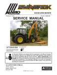
Assembly Instruction Manual
NH TS100A,115A,125A & TS115A
Published 10-04
Manual Part No. 02981048
Tractors equipped with additional options, special equipment, tractor manufacturer modifications,
new tractor models, or Customer alterations may prevent this Mount Kit from being properly
mounted to the tractor. Alamo Group is not responsible for modifications to the MountKit to
accommodate these differences.
ALAMO INDUSTRIAL
1502 E. Walnut
Seguin, Texas 78155
210-379-1480
© 2004 Alamo Group Inc.
TO THE OWNER/OPERATOR/DEALER
All implements with moving parts are potentially hazardous. There is no substitute for a cautious,
safe-minded operator who recognizes the potential hazards and follows reasonable safety
practices. The manufacturer has designed this implement to be used with all its safety equipment
properly attached to minimize the chance of accidents.
BEFORE YOU START!!
Read the safety messages on the implement and shown in your
manual. Observe the rules of safety and common sense!
WARRANTY INFORMATION:
Read and understand the complete Warranty Statement found in this Manual. Fill out the Warranty
Registration Form in full and return it within 30 Days. Make certain the Serial Number of the Machine
is recorded on the Warranty Card and on the Warranty Form that you retain. The use of "will-fit"
parts will void your warranty and can cause catastrophic failure with possible injury or death.
INTRODUCTION
ABOUT THIS MANUAL:
The intent of this publication to provide the competent technician with the information necessary
to perform the CORRECT Assembly to the Alamo Industrial Product. This will, in turn provide for
complete customer satisfaction
It is hoped that the information contained in this and other Manuals will provide enough detail to
eliminate the need for contact of the Alamo Industrial Technical Service Dept. However, it should be
understood that many instances may arrive where correspondence with the Manufacturer is necessary.
CONTACTING MANUFACTURER: (Please help us Help You! Before You Call! )
Alamo Industrial Service Staff Members are dedicated to helping you solve your problem, or
your customer’s service problem as quickly and efficiently as possible. Unfortunately, we receive
entirely to many calls with only a minimum amount of information. In some cases, the correspondent
has never gone out to look at the equipment and merely calls inquiring of the problems described to him
by the operator or customer.
Most calls received by Alamo Industrial Service can be classified into approx. 6 general categories.
1.
Hydraulic or Mechanical Trouble Shooting.
2.
Request for Technical Information or Specifications.
3.
Mounting or Fitting Problem.
4.
Special Service Problem.
5.
Equipment Application Problems.
6.
Tractor Problem Inquiries.
HOW YOU CAN HELP:
Make sure the call is necessary! Most of the calls received may not be necessary if the Dealer
Service Technician would do the following.
1.
Check the Service Information at your Dealership provided by Alamo Industrial, This
would include, Service Bulletins, Information Bulletins, Parts Manuals, Operators Manuals, Assembly
Manual or Service Manual, many of these are available via the Alamo Industrial Internet site (www.AlamoIndustrial.Com). Attempt to diagnose or repair problem before calling.
2.
If a call to Alamo Industrial is needed, Certain Information should be available and ready
for the Alamo Industrial Service Staff. Such information as, Machine Model, Serial Number, Your Dealer
Name, Your Account Number and Any other information that will be useful. This information is vital for
the development of a prompt and correct solution to the problem. This will also help to develop a
database of problems and related solutions, which will expedite a solution to future problems of a similar
nature.
3.
The technician may be asked to provide detailed information about the problem
including the results of any required trouble shooting techniques. If the information is not available, The
technician may be asked to get the information and call back. Most recommendations for repairs will
be based on the procedures listed in the Service Manual / Trouble Shooting Guide and Information
provided by customer.
CONTACT ALAMO INDUSTRIAL:
Alamo Industrial, 1502 E. Walnut St. Seguin TX. 78155, Technical Service Dept. PH: 830-372-2708
Machete (NH TS-100A, 115A.125A & 135A Asy. Man.) 10/04
© 2004 Alamo Group Inc.
Index -3
INDEX - ASSEMBLY INSTRUCTION
Page
Index
Introduction.....................................................................................
General Index.................................................................................
Mounting Restriction.....................................................................
User / Assmbly Notes.....................................................................
Index 3
Index 4 & 5
Index 6 & 7
Index 8
Section 1
Mounting Specifications............................................................. 1-1 to 1-20
Section 2
Mounting Specifications............................................................. 2-1 to 2-8
Section 3
Wheel Counter Weight Parts.............................................................3-2
Wheel Counter Weight Installation.................................................... 3-3
Section 4
Front Pump Drive Parts..................................................................... 4-2
Crankshaft Pulley Preparation........................................................... 4-3 to 4-5
Pump Driveshaft Assembly............................................................... 4-5
Pump Driveshaft Half, Shaft End....................................................... 4-5
Frame Rail Support Installation..........................................................4-8
Hydraulic Tank Mount Frame............................................................ 4-8
Pump Mount Weldment.................................................................... 4-4, 3-5, 3-6
Pump Drive Shaft, Tube End............................................................. 4-6
Pump Installation................................................................................4-6
Section 5
Tractor Hydraulic Connections.......................................................... 5-2 to 5-6
Connect Hoses for Valve to Tractor.................................................. 5-2 to 5-6
Section 6
Modify tractor Exhaust system.......................................................... 6-2
Section 7
Hydraulic Tank & Control Valve Installation...................................... 7-2, 7-3
Install Front Bumper.......................................................................... 7-2, 7-3
Valve Hose Schematic...................................................................... 7-4
Machete (NH TS-100A, 115A.125A & 135A Asy. Man.) 10/04
Index -4
© 2004 Alamo Group Inc.
INDEX - ASSEMBLY INSTRUCTION
Page
Section 8
Mount Seat Bracket........................................................................... 8-2
Install Wire Harness into Cab Area................................................... 8-3
Install and connect Joystick .............................................................. 8-4, 8-5
Wire Schematic................................................................................. 8-5, 8-9, 8-10, 8-11
Cab Decal Installation........................................................................ 8-6
Wire Harness to Valve Connections..................................................8-7, 8-8
Section 9
Frame Rail Assembly........................................................................ 9-2 to 9-8
High Frame Assembly....................................................................... 9-9 to 9-17
Section 10
Counter Weight Weldmnet Mounting................................................ 10-2 to 10-4
Section 11
Lift Cylinder Installation...................................................................... 11-2 & 11-4
Boom Installation to King Post.......................................................... 11-3
Boom Hoses to Main Frame............................................................. 11-4, 11-5
Hoses to Pump. Tank & Valve.......................................................... 11-5
Front Pump Cover............................................................................. 11-6
Section 12
Hose connections to Tank, Pump & Valve....................................... 12-2 to 12-8
Section 13
Head Installation........................................................................... 13-2 to 13-5
Oil Tank Fill Procedure.............................................................. 13-6 to 13-7
Section 14
Optional Lexan RH Door............................................................. 14-2 to 14-4
Section 15
Pre-Dilivery Check List...................................................................... 15-2 to 15-4
Machete (NH TS-100A, 115A.125A & 135A Asy. Man.) 10/04
© 2004 Alamo Group Inc.
Index -5
Section 1
Machete
Mounting Specifications
New Holland Tractor
TS-100A,115A,125A & 115A
Machete (NH TS-100A, 115A.125A & 135A Asy. Man.) 10/04
© 2004 Alamo Group Inc.
1-1
Mounting Specifications
New Holland TS100A Cab/2&4wd
As of 3-3-04
Closed Center, Load Sense Valve
10.00-16 (F-2) Min / 12.4-24 (R-1) Max Front Tire
18.4-30 (R-1) Min / 18.4-34 (R-1) Max Rear Tire
Mount Kits:
Machete Mount Kit …………………………………………..
02980799
Options:
Lexan Window Kit …………………………………………..
Side Screen Kit ………………………………………………
Extra Machete Installation Manual ……………………………
02980888
02980642
02981048
Restrictions:
1. Must be ordered with a high frame due to high opening hood design.
2. This mount kit includes exhaust modification kit #02980717 which allows the vertical A-post style
exhaust to be moved in approximately 8 1/2" for boom transport clearance. (See Figure 1)The right
handrail must also be removed for transport clearance on booms shorter than 24' (See Figure 1)
3. This kit includes a seat-mounted joystick. (See Figure 2) Other seat styles may require modification
of this bracket at the dealer/customer’s expense (See Figure 2)
4. The frame rails have been designed to provide clearance with the New Holland loader brackets
which were incorporated into all production tractors effective January 12, 2004. As a result, the
battery box will no longer hinge outward due to the orientation of the right hand rail. (See Figure 3)
However, the battery can still be accessed and even removed with the assistance of one additional
person.
5. Frame location is very critical in mounting this unit. It must be placed slightly higher than normal to
allow the hood to open enough for air filter maintenance. Failure to set the frame correctly will
warrant modification of the hood.
6. This mount kit includes the Neapco style driveline with double U-joints.
7. The Neapco driveline kit includes a pump box which shifts the hydraulic pump approximately 6 1/4"
forward.
8. Alamo wheel weights fit standard flanged rims only. Other rim types may require an adapter to be
provided at the dealer/customer’s expense.
9. Lexan window insert #02966458 can not be installed with the side screen kit due to the extreme
curvature of the glass door.
10. This mount kit was developed on a Cab/2wd TS100A. Every effort has been made to provide
adequate tire clearance for tractors equipped with mechanical 4wd. Adjustment of the tread setting
and steering stop may be necessary. In addition, an articulation block may be required, but has not
been included at this time. Finally, the hoses in this kit were sized for a 2wd as well. We are hoping
that little to no alteration will be necessary for the 4wd application. However, until a 4wd model is
mounted for inspection at our Seguin facility, the dealer/customer is responsible for all necessary
modifications as mentioned above.
11. Beware, additional counterweight may be required for tractors equipped with a 24' boom. Any such
add on weight must be supplied at the dealer/customer’s expense. Engineering will provide a
recommendation only after such a configuration is mounted at the Seguin facility.
12. The Lexan window kit option is comprised of a molded piece of General Electric brand 3/8" Lexan
with a scratch resistant coating on both sides. It has been designed as a replacement for the standard
right hand, tempered glass door that comes equipped with the tractors (See Figure 4)
Machete (NH TS-100A, 115A.125A & 135A Asy. Man.) 10/04
© 2004 Alamo Group Inc.
1-2
Mounting Specifications
New Holland TS100A Cab/2&4wd
Figure 2: Seat-Mounted Joystick
Figure 1: Replacement Exhaust Pipe
(Elbow) & Bracket
Figure 3: Battery Box Clearance w/RH Frame Rail
Figure 4: Optional Lexan Door Kit
Machete (NH TS-100A, 115A.125A & 135A Asy. Man.) 10/04
© 2004 Alamo Group Inc.
1-3
Mounting Specifications
New Holland TS100A Cab/2&4wd
IMPORTANT NOTICE:
The following Part / Assembly Numbers are for reference and
should not be ordered as replacement parts, unless all the components in that assembly are
wanted. These will break down to bills of material of the components. Some of numbers listed are
NOT individual Parts but complete assemblies and/or box of assemblies. Check before ordering.
02980799 Machete Mount Kit - NH TS100A Cab 2 & 4 WD :
Consist of the Following Items
Item
1.
2.
3.
4.
5.
6.
7.
8.
Part No.
02980804
02980693
02980697
02971969
02970758
02969602
02980800
02980905
Qty
1
1
1
1
1
1
1
1
Description
WLDMT. RAIL LH TS100A MACHETE
WLDMT, BOOM REST NH TS-A
TUBE, CROSSMEMBER
WLDMT, CWT
WEIGHT,WHEEL 1400LBS
WELDMENT, CWT TIE ROD
COMP BOX, NEW HOLLAND TS100A
WLDMT. RAIL RH TS100A MACHETE
02980800 Component Box: Consist of the following Item No.
Item
1
2
3
4
5
6
7
8
9
10
12
13
14
15
16
17
18
19
20
21
22
23
24
Part No.
02725900
02959770
02971538
02980699
02980696
02980667
02980668
02980719
02980694
02980717
02980714
02753400
02966874
000859
00763977
02775500
02963524
02964677
02965093
02965262
02967827
63118700
02980801
Qty
2
2
1
1
1
1
1
1
1
1
1
3
1
2
1
10
1
1
1
1
1
5
1
Description
SUPPORT PLATE
HOSE SUPPORT RING
PLATE, BOOM REST
PULLEY ADAPTER NH TS-A
WLDMT, BOOM REST STABILIZER
WLDMT FRONT MOUNT L.H. TS-A
WLDMT FRONT MOUNT R.H. TS-A
ASSY, TS-A PUMP MOUNT W/COVER
PLATE, BOOM REST STABILIZER
KIT EXHAUST RELOCATION
KIT JOYSTICK SEAT MOUNT
PLASTIC TIE-ON 15 LG
BOOT,CABLE
TIE,PLASTIC
DECAL,NOTICE TO OWNER
PLASTIC TIE 21 LG.
DECAL:ATTENTION-BOOM SWINGING
DECAL,BOOM REST 02980800
DECAL-PROPER ENGINE OPERATING
DECAL- WARNING HOSE BURST
DECAL-MULTI HAZ
02980800
3/16X 7 PLASTIC TIE WRAP
BOLT BAG, NH TS100A MACHETE
Continued Next Page
Machete (NH TS-100A, 115A.125A & 135A Asy. Man.) 10/04
© 2004 Alamo Group Inc.
1-4
Mounting Specifications
New Holland TS100A Cab/2&4wd
Continued From Previous Page
Item
25
26
27
28
29
30
31
32
33
34
38
39
42
43
46
47
48
49
50
51
52
53
54
55
56
57
Part No.
02969509
02969508
02969401
02975000
02980817
02969418
02969419
02969420
02976714
02976719
02976726
02976727
02976730
02976731
02980805
02980807
02977901
02977902
02977903
02977904
02976742
02976743
02981008
02981048
02981129
02982000
Qty
1
1
1
1
1
1
1
1
1
1
1
1
1
1
1
1
1
1
1
1
1
1
1
1
1
1
Description
ADAPTER, HYD ELBOW 12MM - 4MJ 90DEG
ADAPTER, HYD STRAIGHT 22MM - 10MJ
ADAPTER, HYD ELBOW 10FJX - 8MJ 90
ADAPTER, HYD STRAIGHT 12MJ - 27MM
ADAPTER, HYD 12FJX - 8MJ 9
HOSE #16 -16FJX - 16FJX - 66LG
HOSE #16 -16FJX - 16FJX - 66LG
HOSE #16 -16FJX - 16FJX - 62LG
HOSE # 8 - 8FJX - 8FJX - 190” LG
HOSE # 8 - 8FJX - 8FJX90 - 190” LG
HOSE # 6 - 6FJX - 6MJ - 70” LG
HOSE # 6 - 6FJX - 6MJ - 70” LG
HOSE # 6 - 6FJX - 6MJ - 70” LG
HOSE # 6 - 6FJX - 6MJ - 70” LG
RAIL, TANK LH
WLDMT. RH TANK RAIL TS100A
HOSE # 6 - 6FJX - 6MJ - 56” LG
HOSE # 6 - 6FJX - 6MP - 56” LG
HOSE # 6 - 6FJX - 6MP - 76” LG
HOSE # 6 - 6FJX - 6MP - 76” LG
HOSE # 4 - 4FJX - 4MJ - 76” LG
HOSE # 4 - 4FJX - 4MJ - 76” LG
HOSE # 4 - 4FJX - 4FJX - 190” LG
MANUAL,INST NEW HOLLAND TS-A
KIT, HYDRAULIC CONNECTION
DRIVELINE, MODIFIED 02975257A
Component Box P/N 02980800 is in Mount Kit P/N 02980799
02980801 Bolt Bag: Consist of the following Item No.
Item
1
2
3
4
5
6
7
8
9
10
11
Part No.
02918600
00037200
02975692
02971158
00001300
02976344
00022200
02980720
00754566
02980721
02980722
Qty
8
17
12
12
6
4
4
4
4
2
2
Description
HEXB 3/4”-10UNC X 2” PL GR8
LOCKNUT 3/4”-NC, TOPLOCK
HHCS M20-P2.5 -50MM PL GR10.9
LOCKWASHER, 20MM
LOCKWASHER, 1/2”
BOLT, HEX HEAD 7/16”-NC X 1-1/4 PL GR8
LOCKWASHER, 7/16” PL
BOLT, HEX HEAD M12-P1.75 X 40 PL GR10.9
LOCKWASHER, 12MM
BOLT, HEX HEAD 1"-8UNC X 10-1/2” PL GR 8
BOLT, HEX HEAD 1"-8UNC X 11-1/2” PL GR 8
Continued Next Page
Machete (NH TS-100A, 115A.125A & 135A Asy. Man.) 10/04
© 2004 Alamo Group Inc.
1-5
Mounting Specifications
New Holland TS100A Cab/2&4wd
Continued From Previous Page
02980801 Bolt Bag: Consist of the following Item No.
Item
Part No.
Qty
Description
12
13
14
15
16
17
18
19
20
21
22
23
24
25
26
27
28
00059500
02032200
02959587
5312316
02980723
02975957
02970066
02956765
00002700
00001200
02980730
02962777
02963646
02776600
00759635
02976387
00010300
4
4
2
10
4
4
8
4
8
4
4
2
1
2
2
6
6
NUT, HEX 1”-NC PL
LOCKWASHER, STD 1”
BOLT, HEX HEAD, 3/4”-10 NC X 6" PL GR8
WASHER, 3/4" HARDENED
BOLT, HEX HEAD M18-P1.5 X 80 PL GR10.9
BOLT, HEX HEAD M18-P1.5 X 100MM PL GR10.9
LOCKWASHER, 18MM
BOLT, HEX HEAD 1/2”-NC X 4-1/2” PL GR8
FLATWASHER, 1/2 PL STD
NUT, HEX 1/2”-NC PL
BOLT, HEX HEAD 3/4”-10 NC X 4-1/4" PL GR8
BOLT, SOCKET HEAD 3/4”-NC X 11” PL GR8
BOLT, HEX HEAD 3/4”-NC X 2-1/2” PL GR8
BOLT, HEX HEAD 1/2”-NC x 1-1/4” PL GR8
FLATWASHER, HARDENED 1/2” NON-PLTD
BOLT, HEX HEAD 5/8”-NC X 1-1/2” PL GR8
LOCKWASHER, 5/8”
Bolt Bag P/N 02980801 is in Component Box P/N 02980800 which is
in Mount Kit P/N 02980799
02980717 Exhaust Relocation Kit: Consist of the following Item No.
Item
Part No.
Qty
Description
1
2
3
4
5
6
7
8
9
10
11
02980649
02980718
02980584
02980727
02980728
701513C
00754566
02981771
02980584
00753642
00015800
1
1
2
4
3
3
3
1
1
2
2
WELDMENT EXHAUST BRACKET
WELDMENT, TURBO DOWNPIPE
KIT 3" EXHAUST CLAMP
BOLT, SOCKET HEAD, M8-P1.25 X 35mm PL GR10.9
BOLT, HEX HEAD, M12-P1.75 X 30mm PL GR10.9
FLATWASHER, 12 MM
LOCKWASHER, 12MM
EXHAUST STABILIZER BRACKET, TOP
KIT, 3" EXHAUST CLAMP
BOLT, HEX HEAD 3/8”-NC X 1-1/4” PL GR5
LOCKNUT, TOPLOCK 3/8”
Exhaust Relocation Kit P/N 02980717 is in Component Box P/N
02980800 which is in Mount Kit P/N 02980799
Machete (NH TS-100A, 115A.125A & 135A Asy. Man.) 10/04
© 2004 Alamo Group Inc.
1-6
Mounting Specifications
New Holland TS100A Cab/2&4wd
02980714 Joystick Seat Mount Kit: Consist of the following Item No.
Item
Part No.
Qty
Description
1
2
7
8
9
11
12
02980715
00011700
00011400
00012101
00011100
02980635
00753723
1
1
2
2
2
1
1
WELDMENT, JOYSTICK STAND - SEAT MOUNT
LOCKWASHER, 5/16” PL STD
BOLT HEX 3/8”-NC X 1”
LOCKWASHER, 3/8” PL
FLATWASHER, STD 3/8”
DRAWING, INSTALL SEAT MOUNT JOYSTICK
BOLT, HEX HEAD M8-P1.25 X 25mm
Joystick Seat Mount Kit P/N 02980714 is in Component Box P/N
02980800 which is in Mount Kit P/N 02980799
02980719 Pump Mount Kit w/Cover: Consist of the following Item No.
Item
1
2
3
4
5
Part No.
02980666
02980398
00021400
00024100
00017000
Qty
1
1
4
4
4
Description
WLDMT PUMP MOUNT TS-A
COVER, DRIVE LINE
BOLT, HEX HEAD 1/4”- NC X 3/4” PL GR5
FLATWASHER, STD 1/4 “ PL
LOCKWASHER, 1/4” PL ST
Pump Mount Kit P/N 02980719 is in Component Box P/N 02980800
which is in Mount Kit P/N 02980799
Machete (NH TS-100A, 115A.125A & 135A Asy. Man.) 10/04
© 2004 Alamo Group Inc.
1-7
Mounting Specifications
New Holland TS100A ROPS/2&4wd
As of Date: 5-11-04
Closed Center, Load Sense Valve
10.00-16 (F-2) Min / 12.4-24 (R-1) Max Front Tire
18.4-30 (R-1) Min / 18.4-34 (R-1) Max Rear Tire
Mount kits:
Machete Mount Kit (ROPS Only) ……….………….…..…… 02981063
Options:
Aluminum Canopy (FOPS Rated) …………..……..……...... 02980929
Extra Machete Installation Manual …………………………… 02981048
Rear Screen Kit ……………………………………………… 02981109
Restrictions:
1.
2.
3.
4.
5.
6.
7.
8.
9.
10.
11.
Must be ordered with a high frame due to high opening hood design.
This mount kit includes exhaust modification kit #02980717 which allows the vertical A-post
style exhaust to be moved in approximately 8 1/2" for boom transport clearance. (See Figure
1 - TS100A Cab Above)
This kit includes a seat-mounted joystick. Other seat styles may require modification of this
bracket at the dealer/customer’s expense.
The frame rails have been designed to provide clearance with the New Holland load brackets
which were incorporated into all production tractors effective January 12, 2004. As a result,
the battery box will no longer hinge outward due to the orientation of the right hand rail. (See
Figure 3 - TS100A Cab Above) However, the battery can still be accessed and even
removed with the assistance of one additional person.
Frame location is very critical in mounting this unit. It must be placed slightly higher than
normal to allow the hood to open enough for air filter maintenance. Failure to set the frame
correctly will warrant modification of the hood.
This mount kit includes the Neapco style driveline with double U-joints.
The Neapco driveline kit includes a pump box which shifts the hydraulic pump approximately
6-1/4" forward.
Alamo wheel weights fit standard flanged rims only. Other rim types may require an adapter
to be provided at the dealer/customer’s expense.
This mount kit was developed on a Cab/2wd TS100A. Every effort has been made to
provide adequate tire clearance for tractors equipped with mechanical 4wd. Adjustment of
the tread setting and steering stop may be necessary. In addition, an articulation block may
be required, but has not been included at this time. Finally, the hoses in this kit were sized
for a 2wd as well. We are hoping that little to no alteration will be necessary for the 4wd
application. However, until a 4wd model is mounted for inspection at our Seguin facility, the
dealer/customer is responsible for all necessary modifications as mentioned above.
Beware, additional counterweight may be required for tractors equipped with a 24' boom.
Any such add on weight must be supplied at the dealer/customer’s expense. Engineering
will provide a recommendation only after such configuration is mounted at the Seguin facility.
The operator’s “cage” now includes a full Lexan side shield as standard equipment, though
ROPS cages will maintain an expanded metal cover above the operator. Be aware that a
tractor with mounted canopy was unavailable during the development phase of the canopy
cage. Though it should fit fairly well with the Perry Co. brand canopy which we sell, be
aware that some modification may be necessary. Furthermore, the dealer/customer is
responsible for such alterations until a proper check fit can be conducted at Seguin facility.
Machete (NH TS-100A, 115A.125A & 135A Asy. Man.) 10/04
© 2004 Alamo Group Inc.
1-8
Mounting Specifications
New Holland TS100A ROPS/2&4wd
Figure 2: Seat-Mounted Joystick
Figure 1: Replacement Exhaust Pipe
(Elbow) & Bracket
Figure 3: Battery Box Clearance w/RH Frame Rail
Machete (NH TS-100A, 115A.125A & 135A Asy. Man.) 10/04
© 2004 Alamo Group Inc.
1-9
Mounting Specifications
New Holland TS100A ROPS/2&4wd
IMPORTANT NOTICE:
The following Part / Assembly Numbers are for reference and
should not be ordered as replacement parts, unless all the components in that assembly are
wanted. These will break down to bills of material of the components. Some of numbers listed are
NOT individual Parts but complete assemblies and/or box of assemblies. Check before ordering.
02981063 Machete Mount Kit - NH TS100A ROPS 2 & 4 WD :
Consist of the Following Items
Item
1.
2.
3.
4.
5.
6.
7.
8.
9.
Part No.
02980804
02980693
02980697
02971969
02970758
02969602
02981064
02980905
02980998
Qty
1
1
1
1
1
1
1
1
1
Description
WLDMT. RAIL LH TS100A MACHETE
WLDMT, BOOM REST NH TS-A
TUBE, CROSSMEMBER
WLDMT, CWT
WEIGHT,WHEEL 1400LBS
WELDMENT, CWT TIE ROD
COMP BOX, NEW HOLLAND TS100A
WLDMT. RAIL RH TS100A MACHETE
CAGE KIT, NH TS-A ROPS
02981064 Component Box: Consist of the following Item No.
Item
1
2
3
4
5
6
7
8
9
10
12
13
15
16
17
18
19
20
21
22
23
24
Part No.
02725900
02959770
02971538
02980699
02980696
02980667
02980668
02980719
02980694
02980717
02980714
02753400
000859
00763977
02775500
02963524
02964677
02965093
02965262
02967827
63118700
02980801
Qty
2
2
1
1
1
1
1
1
1
1
1
3
2
1
10
1
1
1
1
1
5
1
Description
SUPPORT PLATE
HOSE SUPPORT RING
PLATE, BOOM REST
PULLEY ADAPTER NH TS-A
WLDMT, BOOM REST STABILIZER
WLDMT FRONT MOUNT L.H. TS-A
WLDMT FRONT MOUNT R.H. TS-A
ASSY, TS-A PUMP MOUNT W/COVER
PLATE, BOOM REST STABILIZER
KIT EXHAUST RELOCATION
KIT JOYSTICK SEAT MOUNT
PLASTIC TIE-ON 15 LG
TIE,PLASTIC
DECAL,NOTICE TO OWNER
PLASTIC TIE 21 LG.
DECAL:ATTENTION-BOOM SWINGING
DECAL,BOOM REST
DECAL-PROPER ENGINE OPERATING
DECAL- WARNING HOSE BURST
DECAL-MULTI HAZ
3/16X 7 PLASTIC TIE WRAP
BOLT BAG, NH TS100A MACHETE
Continued Next Page
Machete (NH TS-100A, 115A.125A & 135A Asy. Man.) 10/04
© 2004 Alamo Group Inc.
1 - 10
Mounting Specifications
New Holland TS100A ROPS/2&4wd
Continued From Previous Page
Item
25
26
27
28
29
30
31
32
33
34
38
39
42
43
46
47
48
49
50
51
52
53
54
55
56
57
Part No.
02969509
02969508
02969401
02975000
02980817
02969418
02969419
02969420
02976714
02976719
02976726
02976727
02976730
02976731
02980805
02980807
02977901
02977902
02977903
02977904
02976742
02976743
02981008
02981048
02981129
02982000
Qty
1
1
1
1
1
1
1
1
1
1
1
1
1
1
1
1
1
1
1
1
1
1
1
1
1
1
Description
ADAPTER, HYD ELBOW 12MM - 4MJ 90DEG
ADAPTER, HYD STRAIGHT 22MM - 10MJ
ADAPTER, HYD ELBOW 10FJX - 8MJ 90
ADAPTER, HYD STRAIGHT 12MJ - 27MM
ADAPTER, HYD 12FJX - 8MJ 90
HOSE #16 -16FJX -16FJX - 66” LG
HOSE #16 -16FJX -16FJX - 66” LG
HOSE #16 -16FJX -16FJX - 62” LG
HOSE # 8 - 8FJX - 8FJX - 190” LG
HOSE # 8 - 8FJX - 8FJX90 - 190” LG
HOSE # 6 - 6FJX - 6MJ - 70” LG
HOSE # 6 - 6FJX - 6MJ - 70” LG
HOSE # 6 - 6FJX - 6MJ - 70” LG
HOSE # 6 - 6FJX - 6MJ - 70” LG
RAIL, TANK LH
WLDMT. RH TANK RAIL TS100A
HOSE # 6 - 6FJX - 6MJ - 56” LG
HOSE # 6 - 6FJX - 6MP - 56” LG
HOSE # 6 - 6FJX - 6MP - 76” LG
HOSE # 6 - 6FJX-6MP - 76LG
HOSE # 4 - 4FJX - 4MJ - 76” LG
HOSE # 4 - 4FJX - 4MJ - 76” LG
HOSE # 4 - 4FJX - 4FJX -190” LG
MANUAL,INST NEW HOLLAND TS-A
KIT, HYDRAULIC CONNECTION
DRIVELINE, MODIFIED 02975257A
Component Box P/N 02981064 is in Mount Kit P/N 02981063
02980801 Bolt Bag: Consist of the following Item No.
Item
1
2
3
4
5
6
7
8
9
10
11
Part No.
02918600
00037200
02975692
02971158
00001300
02976344
00022200
02980720
00754566
02980721
02980722
Qty
8
17
12
12
6
4
4
4
4
2
2
Description
HEXB 3/4”-10UNC X 2” PL GR8
LOCKNUT 3/4”-NC, TOPLOCK
HHCS M20-P2.5 -50MM PL GR10.9
LOCKWASHER, 20MM
LOCKWASHER, 1/2”
BOLT, HEX HEAD 7/16”-NC X 1-1/4 PL GR8
LOCKWASHER, 7/16” PL
BOLT, HEX HEAD M12-P1.75 X 40 PL GR10.9
LOCKWASHER, 12MM
BOLT, HEX HEAD 1"-8UNC X 10-1/2” PL GR 8
BOLT, HEX HEAD 1"-8UNC X 11-1/2” PL GR 8
Continued Next Page
Machete (NH TS-100A, 115A.125A & 135A Asy. Man.) 10/04
© 2004 Alamo Group Inc.
1 - 11
Mounting Specifications
New Holland TS100A ROPS/2&4wd
Continued From Previous Page
02980801 Bolt Bag: Consist of the following Item No.
Item
Part No.
Qty
Description
12
13
14
15
16
17
18
19
20
21
22
23
24
25
26
27
28
00059500
02032200
02959587
5312316
02980723
02975957
02970066
02956765
00002700
00001200
02980730
02962777
02963646
02776600
00759635
02976387
00010300
4
4
2
10
4
4
8
4
8
4
4
2
1
2
2
6
6
NUT, HEX 1”-NC PL
LOCKWASHER, STD 1”
BOLT, HEX HEAD, 3/4”-10 NC X 6" PL GR8
WASHER, 3/4" HARDENED
BOLT, HEX HEAD M18-P1.5 X 80 PL GR10.9
BOLT, HEX HEAD M18-P1.5 X 100MM PL GR10.9
LOCKWASHER, 18MM
BOLT, HEX HEAD 1/2”-NC X 4-1/2” PL GR8
FLATWASHER, 1/2 PL STD
NUT, HEX 1/2”-NC PL
BOLT, HEX HEAD 3/4”-10 NC X 4-1/4" PL GR8
BOLT, SOCKET HEAD 3/4”-NC X 11” PL GR8
BOLT, HEX HEAD 3/4”-NC X 2-1/2” PL GR8
BOLT, HEX HEAD 1/2”-NC x 1-1/4” PL GR8
FLATWASHER, HARDENED 1/2” NON-PLTD
BOLT, HEX HEAD 5/8”-NC X 1-1/2” PL GR8
LOCKWASHER, 5/8”
Bolt Bag P/N 02980801 is in Component Box P/N 02981064 which is
in Mount Kit P/N 02981063
02980717 Exhaust Relocation Kit: Consist of the following Item No.
Item
Part No.
Qty
Description
1
2
3
4
5
6
7
8
9
10
11
02980649
02980718
02980584
02980727
02980728
701513C
00754566
02981771
02980584
00753642
00015800
1
1
2
4
3
3
3
1
1
2
2
WELDMENT EXHAUST BRACKET
WELDMENT, TURBO DOWNPIPE
KIT 3" EXHAUST CLAMP
BOLT, SOCKET HEAD, M8-P1.25 X 35mm PL GR10.9
BOLT, HEX HEAD, M12-P1.75 X 30mm PL GR10.9
FLATWASHER, 12 MM
LOCKWASHER, 12MM
EXHAUST STABILIZER BRACKET, TOP
KIT, 3" EXHAUST CLAMP
BOLT, HEX HEAD 3/8”-NC X 1-1/4” PL GR5
LOCKNUT, TOPLOCK 3/8”
Exhaust Relocation Kit P/N 02980717 is in Component Box P/N
02980800 which is in Mount Kit P/N 02980799
Machete (NH TS-100A, 115A.125A & 135A Asy. Man.) 10/04
© 2004 Alamo Group Inc.
1 - 12
Mounting Specifications
New Holland TS100A ROPS/2&4wd
02980714 Joystick Seat Mount Kit: Consist of the following Item No.
Item
Part No.
Qty
Description
1
2
7
8
9
11
12
02980715
00011700
00011400
00012101
00011100
02980635
00753723
1
1
2
2
2
1
1
WELDMENT, JOYSTICK STAND - SEAT MOUNT
LOCKWASHER, 5/16” PL STD
BOLT HEX 3/8”-NC X 1”
LOCKWASHER, 3/8” PL
FLATWASHER, STD 3/8”
DRAWING, INSTALL SEAT MOUNT JOYSTICK
BOLT, HEX HEAD M8-P1.25 X 25mm
Joystick Seat Mount Kit P/N 02980714 is in Component Box P/N
029801064 which is in Mount Kit P/N 02981063
02980719 Pump Mount Kit w/Cover: Consist of the following Item No.
Item
1
2
3
4
5
Part No.
02980666
02980398
00021400
00024100
00017000
Qty
1
1
4
4
4
Description
WLDMT PUMP MOUNT TS-A
COVER, DRIVE LINE
BOLT, HEX HEAD 1/4”- NC X 3/4” PL GR5
FLATWASHER, STD 1/4 “ PL
LOCKWASHER, 1/4” PL ST
Pump Mount Kit P/N 02980719 is in Component Box P/N 02981064
which is in Mount Kit P/N 02981063
Machete (NH TS-100A, 115A.125A & 135A Asy. Man.) 10/04
© 2004 Alamo Group Inc.
1 - 13
Mounting Specifications
New Holland TS115A/125A/135A Cab/2&4wd
Closed Center, Load Sense Valve
10.00-16 (F-2) Min / 14.9-24 (R-1W) Max Front Tire
18.4-30 (R-1) Min / 18.4-34 (R-1W) Max Rear Tire
As of Date: 4-3-04
Mount Kits:
Machete Mount Kit ………………………………………….......02980902
Options:
Lexan Window Kit …………………………………………....... 02980888
Side Screen Kit ………………………………………………....02980642
Extra Machete Installation Manual …………………………… 02981048
Restrictions:
1. Must be ordered with a high frame due to high opening hood design.
2. This mount kit includes exhaust modification kit #02980916 allowing the vertical A-post style
exhaust to be moved in approx 6-1/2" for boom transport clearance. (Figure 1 & 4) As a result,
the RH loader bracket (included on most models) must be removed for proper exhaust
clearance. The right handrail may also need to be removed for transport clearance on most
booms.
3. This kit has seat-mounted joystick. (See Figure 2 - TS100A Cab Above) Other seat styles
may require modification of this bracket at the dealer/customer’s expense.
4. The frame rails are designed to provide clearance w/ the New Holland loader brackets which
were incorporated in all production tractors effective January 12, 2004. As a result, the battery
box will no longer hinge outward due to the orientation of the right hand rail. (See Figure 3 TS100A Cab Above) However, the battery can still be accessed and even removed with the
assistance of one additional person.
5. Frame location very critical in mounting unit. It must be placed slightly higher than normal to
allow hood to open enough for air filter maintenance. Failure to set the frame correctly will
warrant modification of the hood.
6. This mount kit has Neapco style driveline w/ double U-joints. The Neapco driveline kit includes
a pump box which shifts the hydraulic pump approximately 6-1/4" forward.
8. Alamo wheel weights fit standard flanged rims only. Other rim types may require an adapter to
be provided at the dealer/customer’s expense.
9. Lexan window insert #02966458 can not be installed with the side screen kit due to the
extreme curvature of the glass door.
10. Mount kit was developed f/ Cab/4wd TS115A A-Boom. Every effort was made to for adequate
tire clearance for tractors equipped with mechanical 4wd. Adjustment of the tread setting and
steering stop may be necessary. In addition, an articulation block may be required, but has not
been included at this time. Finally, the hoses in kit were sized from the TS100A (4 cyld)
Machete. We are hoping that little to no alteration will be necessary for the 6 cyld application.
Furthermore, the TS125A & 135A are reportedly equipped with Iveco engines.Though the
driveline should fit correctly to the crankshaft pulley, we have no way of checking for proper
driveline access. Until all three models have been mounted for inspection at our Seguin facility,
the dealer/customer will be held responsible necessary modifications as mentioned above.
11. Beware, additional counterweight may be required for tractors equipped with a 24' boom.
Any such add on weight must be supplied at the dealer/customer’s expense. Engineering will
provide a recommendation only after such a configuration is mounted at the Seguin facility.
12. The Lexan window kit option is comprised of a molded piece of General Electric brand 3/8"
Lexan with a scratch resistant coating on both sides. It has been designed as a replacement
for the standard right hand, tempered glass door that comes equipped with the tractors.
Machete (NH TS-100A, 115A.125A & 135A Asy. Man.) 10/04
© 2004 Alamo Group Inc.
1 - 14
Mounting Specifications
New Holland TS115A/125A/135A Cab/2&4wd
Figure 2: Seat-Mounted Joystick
Figure 1: Replacement Exhaust Pipe
(Elbow) & Bracket
Figure 3: Battery Box Clearance w/RH Frame Rail
Figure 1: Replacement Exhaust
(Prototype Shown)
Machete (NH TS-100A, 115A.125A & 135A Asy. Man.) 10/04
© 2004 Alamo Group Inc.
1 - 15
Mounting Specifications
New Holland TS115A/125A/135A Cab/2&4wd
IMPORTANT NOTICE:
The following Part / Assembly Numbers are for reference and
should not be ordered as replacement parts, unless all the components in that assembly are
wanted. These will break down to bills of material of the components. Some of numbers listed are
NOT individual Parts but complete assemblies and/or box of assemblies. Check before ordering.
02980902 Machete Mount Kit - NH TS115A, 125A & 135A Cab 2/4 WD:
Consist of the Following Items
Item
1
2
3
4
5
6
7
8
9
Part No.
02915300
02980693
02980697
02971969
02970758
02969602
02980903
02980896
02980904
Qty
1
1
1
1
1
1
1
1
1
Description
SLOPEMOWER SHIPPING PALLET
WLDMT, BOOM REST NH TS-A
TUBE, CROSSMEMBER
WLDMT, CWT JD 6000 SERIES
WEIGHT,WHEEL 1400LBS
WELDMENT, CWT TIE ROD
COMP. BOX NH TS115A MACHETE
WLDMT. RAIL LH TS115A MACHETE
WLDMT. RAIL RH TS115A MACHETE
02980903 Component Box: Consist of the following Item No.
Item
1
2
3
4
5
6
7
8
9
12
13
14
15
16
17
18
19
20
21
22
23
25
Part No.
02725900
02959770
02971538
02980699
02980696
02980667
02980668
02980719
02980694
02980714
02753400
02966874
000859
00763977
02775500
02963524
02964677
02965093
02965262
02967827
63118700
02969509
Qty
2
2
1
1
1
1
1
1
1
1
3
1
2
1
10
1
1
1
1
1
5
1
Description
SUPPORT PLATE
HOSE SUPPORT RING
PLATE, BOOM REST
PULLEY ADAPTER NH TS-A
WLDMT, BOOM REST STABILIZER
WLDMT FRONT MOUNT L.H. TS-A
WLDMT FRONT MOUNT R.H. TS-A
ASSY, TS-A PUMP MOUNT W/COVER
PLATE, BOOM REST STABILIZER
KIT JOYSTICK SEAT MOUNT
PLASTIC TIE-ON 15 LG
BOOT,CABLE
TIE,PLASTIC
DECAL,NOTICE TO OWNER
PLASTIC TIE 21 LG.
DECAL:ATTENTION-BOOM SWINGING
DECAL,BOOM REST
DECAL-PROPER ENGINE OPERATING
DECAL- WARNING HOSE BURST
DECAL-MULTI HAZ
3/16X 7 PLASTIC TIE WRAP
ADAPTER, HYD ELBOW 12MM - 4MJ - 90 DEG
Continued Next Page
Machete (NH TS-100A, 115A.125A & 135A Asy. Man.) 10/04
© 2004 Alamo Group Inc.
1 - 16
Mounting Specifications
New Holland TS115A/125A/135A Cab/2&4wd
Continued From Previous Page
Item
26
27
28
29
30
31
32
33
34
38
39
42
43
46
47
48
49
50
51
52
53
54
55
56
57
58
59
Part No.
02969508
02969401
02975000
02980817
02969418
02969419
02969420
02976714
02976719
02976726
02976727
02976730
02976731
02980805
02980807
02980916
02980963
02977901
02977902
02977903
02977904
02976742
02976743
02981008
02981048
02981129
02982000
Qty
1
1
1
1
1
1
1
1
1
1
1
1
1
1
1
1
1
1
1
1
1
1
1
1
1
1
1
Description
ADAPTER HYD, STRAIGHT 22MM - 10MJ
ADAPTER HYD, ELBOW 10FJX - 8MJ 90
ADAPTER HYD, STRAIGHT 12MJ - 27MM
ADAPTER HYD, 12FJX - 8MJ 90
HOSE #16 - 16FJX -16FJX - 66” LG
HOSE #16 - 16FJX -16FJX - 66” LG
HOSE #16 - 16FJX -16FJX - 62” LG
HOSE # 8 - 8FJX - 8FJX - 190” LG
HOSE # 8 - 8FJX - 8FJX90 - 190” LG
HOSE # 6 - 6FJX - 6MJ - 70” LG
HOSE # 6 - 6FJX - 6MJ - 70” LG
HOSE # 6 - 6FJX - 6MJ - 70” LG
HOSE # 6 - 6FJX - 6MJ - 70” LG
RAIL, TANK LH
WLDMT. RH TANK RAIL TS100A
KIT, EXHAUST RELOCATION TS115A
BOLT BAG, NH TS115A MACHETE
HOSE # 6 - 6FJX - 6MJ - 56” LG
HOSE # 6 - 6FJX - 6MP - 56” LG
HOSE # 6 - 6FJX - 6MP - 76” LG
HOSE # 6 - 6FJX - 6MP - 76LG
HOSE # 4 - 4FJX - 4MJ - 76” LG
HOSE # 4 - 4FJX - 4MJ - 76” LG
HOSE # 4 - 4FJX - 4FJX -190” LG
MANUAL,INST NEW HOLLAND TS-A
KIT, HYDRAULIC CONNECTION
DRIVELINE, MODIFIED 02975257A
Component Box P/N 02980903 is in Mount Kit P/N 02980902
02980963 Bolt Bag: Consist of the following Item No.
Item
1
2
4
5
7
8
9
10
11
Part No.
02918600
00037200
02975692
02971158
00001300
02976344
00022200
02980967
00754566
Qty
8
17
12
12
6
4
4
4
4
Description
BOLT, HEX HEAD 3/4”-10UNC X 2” PL GR8
LOCKNUT, TOPLOCK 3/4”-NC
BOLT, HEX HEAD M20-P2.5 X 50MM PL GR10.9
LOCKWASHER, 20MM
LOCKWASHER, 1/2”
BOLT, HEX HEAD 7/16”-NC X 1-1/4” PL GR8
LOCKWASHER, 7/16” PL
BOLT, HEX HEAD M12-P1.75 X 60mm PL GR10.9
LOCKWASHER, 12MM
Continued Next Page
Machete (NH TS-100A, 115A.125A & 135A Asy. Man.) 10/04
© 2004 Alamo Group Inc.
1 - 17
Mounting Specifications
New Holland TS115A/125A/135A Cab/2&4wd
Continued From Previous Page
Item
Part No.
Qty
12
02980721
2
13
02980722
2
14
00059500
4
15
02032200
4
16
02959587
2
18
5312316
10
19
02980723
4
20
02975957
4
21
02970066
8
22
02956765
4
23
00002700
8
24
00001200
4
25
02980730
4
26
02962777
2
27
02963646
1
28
02776600
2
29
00759635
2
30
02976387
6
31
00010300
6
Description
BOLT, HEX HEAD 1"-8UNC X 10-1/2” PL GR8
BOLT, HEX HEAD 1"-8UNC X 11-1/2 PL GR8
NUT, HEX 1”-NC PL
LOCKWASHER, STD 1”
BOLT, HEX HEAD, 3/4”-10 NC X 6" PL GR8
WASHER, 3/4" HARDENED
BOLT, HEX HEAD M18-P1.5 X 80 mm PL GR10.9
BOLT, HEX HEAD M18-P1.5 X 100MM PL GR10.9
LOCKWASHER, 18MM
BOLT, HEX HEAD 1/2”-NC X 4-1/2” PL GR8
FLATWASHER, STD 1/2” PL
NUT, HEX 1/2”-NC PL
BOLT, HEX HEAD 3/4”-10 NC X 4-1/4" PL GR8
BOLT, SOCKET HEAD 3/4”-NC X 11” PL GR8
BOLT, HEX HEAD 3/4”-NC X 2-1/2” PL GR8
BOLT, HEX HEAD 1/2”-NC
FLATWASHER, HARDENED 1/2” NON-PLTD
BOLT, HEX HEAD 5/8”-NC X 1-1/2” PL GR8
LOCKWASHER, 5/8”
Bolt Bag P/N 02980963 is in Component Box P/N 02980903
which is in Mount Kit P/N 02980902
02980916 Exhaust Relocation Kit: Consist of the following Item
No.
Item
Part No.
Qty
Description
1
2
3
4
5
6
02980917
02980728
701513C
00754566
02980933
02959132
1
3
3
3
1
2
PIPE, EXHAUST NH TS115A
BOLT, HEX HEAD, M12-P1.75 X 30mm PL GR10.9
FLATWASHER, 12 MM
LOCKWASHER, 12MM
EXHAUST bRACKET WELDMENT
CLAMP, 3-1/2” HD MUFFLER CLAMP
Exhaust Relocation Kit P/N 02980916 is in Component Box P/N
02980903 which is in Mount Kit P/N 02980902
Machete (NH TS-100A, 115A.125A & 135A Asy. Man.) 10/04
© 2004 Alamo Group Inc.
1 - 18
Mounting Specifications
New Holland TS115A/125A/135A Cab/2&4wd
02980714 Joystick Seat Mount Kit: Consist of the following Item No.
Item
Part No.
Qty
Description
1
2
3
4
5
6
7
02980715
00011700
00011400
00012101
00011100
02980635
00753723
1
1
2
2
2
1
1
WELDMENT, JOYSTICK STAND - SEAT MOUNT
LOCKWASHER, 5/16” PL STD
BOLT HEX 3/8”-NC X 1”
LOCKWASHER, 3/8” PL
FLATWASHER, STD 3/8”
DRAWING, INSTALL SEAT MOUNT JOYSTICK
BOLT, HEX HEAD M8-P1.25 X 25mm
Joystick Seat Mount Kit P/N 02980714 is in Component Box P/N
02980903 which is in Mount Kit P/N 02980902
02980719 Pump Mount Kit w/Cover: Consist of the following Item No.
Item
1
2
3
4
5
Part No.
02980666
02980398
00021400
00024100
00017000
Qty
1
1
4
4
4
Description
WLDMT PUMP MOUNT TS-A
COVER, DRIVE LINE
BOLT, HEX HEAD 1/4”- NC X 3/4” PL GR5
FLATWASHER, STD 1/4 “ PL
LOCKWASHER, 1/4” PL ST
Pump Mount Kit P/N 02980719 is in Component Box P/N 02980903
which is in Mount Kit P/N 0298902
02981129 Hydraulic Connection Kit: Consist of the following Item No.
Item
1
2
3
4
5
6
7
8
9
10
Part No.
02981117
02981118
02981128
02967151
02981071
00753723
02970065
02974929
02981132
02981131
Qty
1
1
1
1
1
2
2
2
1
1
Description
ADAPTER HYD, TEE 8FFX-8MF-8MF
ADAPTER, HYD STRAIGHT 8FFX-8MF
HOSE, #8 8FJX - 8FJX - 7LG
ADAPTER, HYD STRAIGHT
HOSE #4 - 4FJX - 4FJX -72"
BOLT, HEX HEAD M8-P1.25 X 25mm
LOCKWASHER, 8mm
WASHER 8mm
VALVE BODY MOUNTING. PLATE ASY
INSERT SHEET NH TSA
Hydraulic Connection Kit P/N 02981129 is in Component Box P/N
02980903 which is in Mount Kit P/N 02980902
Machete (NH TS-100A, 115A.125A & 135A Asy. Man.) 10/04
© 2004 Alamo Group Inc.
1 - 19
NOTES
Machete (NH TS-100A, 115A.125A & 135A Asy. Man.) 10/04
© 2004 Alamo Group Inc.
1 - 20
Section 2
Machete
Tractor Preparation
New Holland Tractor
TS-100A,115A,125A & 115A
Machete (NH TS100A, 115A, 125A, 135A Asy. Manual) 10/04
© 2004 Alamo Group Inc.
Section2 - 1
Tractor Preparations
GENERAL INFORMATION:
The tools you will need at the assembly site are as follows:
1.
2.
3.
4.
5.
6.
7.
8.
9.
Impact wrench or socket and ratchet set.
Rubber mallet.
Box-end, Allen, and adjustable wrenches.
Alignment pins.
Forklift or hydraulic floor jacks with rolling back boards.
Small chain hoist or block-and-tackle.
Multidirectional Levels.
Hydraulic Filter Buggy or Cart.
Safety shoes, safety glasses, and gloves.
A hard hat should be worn by anyone working under any raised component.
Remember to follow each step closely and cautiously. Be aware of all support personnel at all times.
Keep the assembly area as clean as possible; clean up all spills when they occur. An uncluttered
assembly area and a crew that is sensitive to the hazards involved in putting this implement together
will help prevent accidents. Keep all unauthorized personnel from the area. Do not allow children near
the assembly site nor allow them on or near the tractor after assembly. There is no safe place for
anyone except the operator on the tractor and those assisting with the assembly.
To help you assemble your new Machete Boom and mount it to your tractor, a detailed assembly
instruction Manual is being provided with the mount kit to provide detailed instructions and part
numbers. Please consult this document for specific information. When needed, you can get
additional information or clarification from Your Dealer or Alamo Group Customer Service.
This publication provides general information not specifically for your case or tractor, but, in
connection with the drawings, this publication offers you some valuable assistance - please read
it thoroughly.
These mount kits are made for selected tractors with standard configurations. Only the noted
options and tire sizes listed in the Mounting Specifications will work with these mount kits. Other
options, front axles, or different tire sizes may prevent the mount kit from fitting your nonstandard
tractor. Alamo Group cannot take responsibility for these problems or any modifications made to
the unit.
Throughout these instructions, references are made to right or left directions. Right and left are
determined by sitting on the tractor seat and facing the direction of travel forward always.
This is the Safety-Alert symbol. When you see this symbol on your machine or in
these instructions, be alert to the potential for personal injury. Follow recommended
precautions and safe operating practices.
DANGER!
A signal word - DANGER, WARNING, or CAUTION - is used with the Safety Alert
symbol. DANGER identifies the most serious hazards.
Machete (NH TS100A, 115A, 125A, 135A Asy. Manual) 10/04
© 2004 Alamo Group Inc.
Section 2 - 2
Tractor Preparations
WARNING!
Safety signs with signal word
serious hazards.
WARNING are typically used to point out more
CAUTION!
General precautions are listed on CAUTION safety sign. CAUTION also calls
attention to safety messages in these instructions.
GENERAL INFORMATION
The tools you will need at the assembly site are as follows:
1.
2.
3.
4.
5.
6.
7.
8.
9.
10.
11.
12.
Welding equipment (including correct head gear, eye shields, and protective clothing.)
Impact wrench or socket and ratchet set.
Rubber mallet.
Box-end, Allen, and crescent wrenches.
Alignment pins.
Phillips and plain-head screwdrivers.
Forklift or hydraulic floor jacks with rolling back boards.
Small chain hoist or block-and-tackle.
Multidirectional Levels.
Paint Scraper.
Hydraulic Filter Buggy or Cart.
Safety shoes, safety glasses, and gloves. A hard hat should be worn by anyone
working under any raised component.
Remember to follow each step closely and cautiously. Be aware of all support personnel at all times.
Keep the assembly area as clean as possible; clean up all spills when they occur. An uncluttered
assembly area and a crew that is sensitive to the hazards involved in putting this implement together
will help prevent accidents. Keep all unauthorized personnel from the area. Do not allow children near
the assembly site nor allow them on or near the tractor after assembly. There is no safe place for
anyone except the operator on the tractor and those assisting with the assembly.
Machete (NH TS100A, 115A, 125A, 135A Asy. Manual) 10/04
© 2004 Alamo Group Inc.
Section2 - 3
Tractor Preparations
WARNING!
Disconnect the negative lead (ground) from the battery terminal to prevent any
damage to the electrical system.
LEVELING TRACTOR:
TRACTOR MUST be on level ground before assembly is begun. The tractor must be level, All tires
must have the proper amount of air in them as per tire and/or Tractors manufactures recommendations.
DO NOT level tractor by over inflating tires. The tractor can be leveled by jacking it up and putting it on
jack stands if needed.
Replacement Oil Filter
Included in the packing box of this unit is a replacement filter element for filter assembly in the tank.
This Mower unit's hydraulic components have been carefully cleaned and packaged at the factory to
prevent contamination from entering the system. However, dust and dirt particles may enter into the
sealed components through transportation, handling, rain, or just sitting in a dirty or harsh environment.
Therefore to assure that the hydraulic system is properly clean, please prepare the area where the unit
is to be assembled. The area should be on a hard concrete floor that has been swept clean of all dust
and contaminants. Unpacked the Mower unit carefully so that the seals on the hydraulic components
are not broken or pulled off.
WARNING!
Before attempting to assemble the mower to the tractor, move the tractor to a clean
solid surface, preferably a concrete shop surface with an over head crane. The crane
should have a rated capacity to lift the heaviest component or assembly. A 5-ton crane
is recommended for the assembly work. If a smaller crane is used, be sure not to
exceed the rated capacity of the crane.
!
Always follow all OSHA crane operating and inspection rules, regulations,
inspection requirements, and recommended practices when using the crane.
!
Never work under any component that is lifted by the crane.
Machete (NH TS100A, 115A, 125A, 135A Asy. Manual) 10/04
© 2004 Alamo Group Inc.
Section 2 - 4
Tractor Preparations
WARNING! Wear personal protective equipment when assembling the mower. As a minimum that
should include:
! Safety Glasses
! Hard Hat
WARNING!
! Safety Shoes
! Hearing Protection
! Gloves
! Welding Helmet
Before attempting to assemble ensure that the tractor engine is off and the tractor
transmission is in the park position with the parking brake engaged.
!
!
!
!
Remove the engine key and keep it in your pocket to prevent inadvertent
starting or movement of the tractor.
Place wheel blocks in front and behind the tractor wheels to prevent the tractor
from moving.
Never attempt to start the tractor unless properly seated in the tractor seat
with the seat belt fastened around you.
Never attempt to operate the tractor and mower controls unless seated in
the tractor seat with the seat belt fastened around you.
WARNING!
Securely block up and support the tractor before attempting to loosen and move the
tires. Failure to properly block up the tractor can result in the tractor to suddenly move
or fall, crushing you or another worker.
!
Never work under any raised component or any component that is not
securely blocked up or supported.
WARNING!
Many components of this mower are very heavy and must be handled by proper
material handling equipment. Do not lift components that weight over 50lbs by
yourself.
!
Use an overhead crane, forklift, or other coworkers to lift heavy items. Ensure
lifted components are securely supported.
!
Never walk or work under a lifted component.
WARNING!
Use extreme care when moving, handling or adjusting the tractor tires. The tires are
extremely heavy and could fall and crush you
!
Use an overhead crane or forklift to move the tires.
!
Properly fasten the tires to the material handling equipment to prevent the tire
from falling.
The hydraulic oil is under high pressure and a hydrauli leak can cause oil to be injected
under the skin.
!
Before starting the tractor ensure all hydraulic connections have bee tightened
!
Never check for leaks with your hands. Use a piece of wood or cardboard to
check for the leak making sure your hands and face are kept away from the
leak area.
!
Repair any leaks before operating the equipments
!
Clean up all oil that has leaked according to the requirements of the oil supplier.
Oil residue on the ground can result in unjury from slipping or falling.
WARNING!
Machete (NH TS100A, 115A, 125A, 135A Asy. Manual) 10/04
© 2004 Alamo Group Inc.
Section2 - 5
Tractor Preparations
TRACTOR PREPARATION (FIGURE 1 & 2)
1. Temporally remove ROPS and fenders from tractor axle. Move left rear tire out so that it is 50 inches
from the outside of left rear tire to the center of tractor. Then move the right rear tire out so that it is 96
inches between the outside of the left and right rear tires. Refer to your tractor’s Operator’s Manual for
instructions on Rear Wheel Adjustment for your particular tire. FIGURE 1. Hydraflate rear left tire as
much as needed for stability but stay in factory-recommend limit.
FIGURE 1
50"
96"
WARNING:
Never operate the tractor with a loose wheel rim or disc. Always tighten nuts
to the specified torque and at the recommended intervals.
2. Extend front wheels out so that it is 55" inches between the inside of the tires. This will allow
no interference between tire and front mount bracket. FIGURE 2.
FIGURE 2
55"
Tractor, Area Cleanliness
The Tractor, all tools and work area must be clean of dirt and debris when assembling any hydraulic
components. DO NOT leave any hydraulic component open to the elements. DO not use any containers
for fluids that are not clean and free of any other liquids. DO NOT use rags/cloth that has lint or fuzz on
them when working on hydraulic components. Keep all hoses capped until you are ready to connect
them.
Machete (NH TS100A, 115A, 125A, 135A Asy. Manual) 10/04
© 2004 Alamo Group Inc.
Section 2 - 6
Mount Kit Component Preparations
Lay Out Components in Display. It is helpful to lay out the component in as neat a display
as possible. Lay out the Bolts according to size and length. Lay out the Nuts and washer by size. This
will allow you to see how many of each part as you use them and help to identify any missing parts. (See
figure 6) See Mount Kit Specification and Component Identification Section to help ID Components.
All the component that are received should be check and sorted as to what they are.
HOSE END FITTING TORQUE SPECS:
Hose End Type: 37 Degree Angle End Steel Hose End Fittings*
Dash
Nominal Cyl.
Torque
Torque
Size
Size (in.)
in. lbs.
ft .lbs.
-4
1/4"
140
12
-6
3/8"
230
19
-8
1/2"
450
38
-10
5/8"
650
54
-12
3/4"
900
75
-16
1"
1200
100
-20
1-1/4"
1600
133
-24
1-1/2"
2000
167
-32
2"
2800
233
* Straight Threads do not always seal better when higher torques are used. Too much torque causes
distortion and may lead to leakage. DO NOT over torque fittings and DO NOT allow any contaminants to enter system through fittings when installing them.
Machete (NH TS100A, 115A, 125A, 135A Asy. Manual) 10/04
© 2004 Alamo Group Inc.
Section2 - 7
Bolt & Hose Fitting Torque Charts
Special Torque Specifications (Rotary Heads)
Motor to Spindle Housing.........................................................
Spindle to Deck........................................................................
Spindle to Adjusting Nut (Bearing Preload)..............................
Blade Bar Leaf Bolts Old Style 7/8" Bolts...............................
New Style 1-1/4" Bolts...........................
Blade Bar to Spindle Bolts.........................................................
Blade Bolts.................................................................................
Motor Plate.................................................................................
100 ft. lbs.
425 ft. lbs.
25 in. lbs. Rolling Torque
600 ft. lbs.
2000 ft. lbs.
400 ft. lbs.
400 ft. lbs.
See Set Up Instructions
TORQUE VALUES - BOLTS: Recommended Torque, Ft. lbs.
& (Nm)
IMPORTANT! Listed below IS BOLT TORQUE and NOT APPLICATION TORQUE, Component
Application Torque will vary depending on what is bolted down and the type material (Metal) that is being
bolted together. Thread condition and lubrication will vary Torque settings.
Inche Sizes
Bolt
Dia.
inch
1/4
5/16
3/8
7/16
1/2
9/16
5/8
3/4
7/8
1
1-1/8
1-1/4
2 (B)
5 (D)
Metric Sizes
8 (F)
Plain Head 3 Dashes 6 Dashes
Not Used
Not Used
Not Used
35 (47)
55 (75)
75 (102)
105 (142)
185 (251)
160 (217)
250 (339)
330 (447)
480 (651)
10 (14)
20 (27)
35 (47)
55 (75)
85 (115)
130 (176)
170 (230)
300 (407)
445 (603)
670 (908)
910 (1234)
1250 (1695)
14 (19)
30 (41)
50 (68)
80 (108)
120 (163)
175 (230)
240 (325)
425 (576)
685 (929)
1030 (1396)
1460 (1979)
2060 (2793)
ALWAYS
CHECK
MARKINGS
ON
TOP
OF
BOLT
HEAD
OR
OTHER
BOLT
DESCRIPTIONS
Machete (NH TS100A, 115A, 125A, 135A Asy. Manual) 10/04
© 2004 Alamo Group Inc.
Section 2 - 8
Bolt
Dia.
mm
6
8
10
12
14
16
18
20
22
24
27
30
33
36
4.8
5
11
20
37
60
92
118
160
215
285
450
600
800
900
8.8
7
20
40
70
100
155
216
270
330
500
875
1200
1600
2100
10.8
12
25
58
105
140
200
280
355
430
700
1000
1700
2300
3000
Section 3
MACHETE
New Holland Tractor
TS-100A,115A,125A & 115A
Wheel Weight
Installation
Machete (NH TS-100A, 115A.125A & 135A Asy. Man.) 10/04
© 2004 Alamo Group Inc.
Section 3 - 1
Rear Wheel Counter Weight
Fill Left Rear Wheel with Liquid:
The Left Rear Wheel must be filled with liquid. Alamo Industrial recommends a Calcium
Chloride Water Mixture. The recommended Ratio of a 30 / 70 mix (30% Calcium Chloride and 70%
Water), this mixture will add weight at about 10.5 lbs per gallon. Follow the Mixture procedures
furnished by the Manufactured of the Brand of Calcium Chloride that you are using. It is also
recommended that a trained person installs the calcium Chloride. Calcium Chloride must be added
in addition to the Steel Wheel Weight and the Counter Weight that hangs on the Left Side. It is Not
recommended to use straight Water in the Wheel as this would not provide protection against freezing.
A 30/70 Calcium Chloride Water mixture provides antifreeze to approx -50 deg. F. below 0.
Rotate Washer to Match Bolt
Circle dia. and Washer fits into
Wheel Weight Slot.
4
3
2
1
Bolt is shown extra long in
drawing for illustration only
Item
Part No.
Qty
Description
1
2
3
4
02979603
02971569
02970758
5JRC1490
3
3
1
3
Hex Head Bolt, 7/8" NC X 16"
Wheel Weight Washer, Special
Wheel Weight Casting, 1400 lbs.
Locknut, Top Lock 7/8" NC
Note: some Older Units used a All Thread Rod with Hex Nuts Lock Nuts, with Flat Washer
and Lock washer. This was replaced with the Bolt Type shown above. These Bolt and Nut
combinations will replace the old All Thread type.
Figure 1
Machete (NH TS-100A, 115A.125A & 135A Asy. Man.) 10/04
© 2004 Alamo Group Inc.
Section 3 - 2
Rear Wheel Counter Weight
Installing Wheel Weight
1.
This Wheel Weight is 1400
lbs. Always use caution when
working with it.
2.
Locate the three Holes in
LH Rear Wheel. Make sure these
holes are 15/16" dia. if not, they
must be reamed out.
3.
Lift Left Rear Tractor
Wheel till it just clears the ground.
This will allow the Wheel to be
rotated when aligning mounting
holes for Weight.
4.
Using a forklift, lift Wheel
Weight into Wheel. When Wheel
Weight is centered in Wheel Secure Forklift and Set Parking Brake
on Forklift. Insert one of the three
bolts through Weight and Wheel
(Rotate Wheel to align holes if
needed). Install a Hex Lock Nut on
inside. Insert the other two Bolts
through Weight and Wheel and
start the other two Locknuts. Do
not tighten yet. (See Figure 2)
Wheel Weight Mntg
Locknuts
Figure 2
5.
Looking at the outside
make sure the three special Washers (Figure 1 Item 2) are aligned
with the Slots in the Wheel Weight.
Tighten the three Bolts now. You
will need an assistant to hold the
other Side while you are tightening
the Bolts. While tightening Bolts,
check to make sure the three special washers are seated correctly.
If these Bolts are tightened and
washer are not seated into the
recess on Wheel Weight, damage will occur. (See Figure 3)
Wheel Weight
Special Washers
Mounting
Bolts
Part #
02971569
(3)
6.
Remove forklift away from
Wheel and Weight. Recheck tightness of Wheel Weight retaining
Bolts. Bolts should torque to 500
ft. lbs.
Figure 3
Machete (NH TS-100A, 115A.125A & 135A Asy. Man.) 10/04
© 2004 Alamo Group Inc.
Section 3 - 3
Wheel Weight
1400 lbs.
NOTES
Machete (NH TS-100A, 115A.125A & 135A Asy. Man.) 10/04
© 2004 Alamo Group Inc.
Section 3 - 4
Section 4
MACHETE
New Holland Tractor
TS-100A,115A,125A & 115A
Front Pump &
Drive Shaft
Installation
Machete (NH TS-100A, 115A.125A & 135A Asy. Man.) 10/04
© 2004 Alamo Group Inc.
Section 4 - 1
Pump / Drive Assembly Instructions
Installing Pump, Pump Drive Components and Hydraulic Tank:
This Section covers the installation of Pump Drive Components, Pump Assembly and the
Hydraulic Tank. Some precautions must be followed during the Assembly Process and before unit is
ever started for the first time.
1. Tractor must be disabled to prevent accidental engine start and prevent damage to components.
2. All Fittings, Hose, Cylinders, Tank must be kept plugged at all times, No part of the Hydraulic
System can be left open at any time during mounting process, this will keep system clean.
3. All Tools, Work Area, Components and Workers Hands must remain Clean when working on
any part of the Hydraulic System.
4. All components should be rechecked for tightness at least twice, Hose routing also double
checked.
Preparing Tractor Front
Plate (Bolster) to Slide
Driveline in From Engine
Side :
Air After-Cooler
Cover removed
1.
Preparing Tractor, On the
Left side of Tractor there are some
engine protective shields that will
have to be removed to install pulley
adapter and driveshaft half (See Figure 2). The shaft half of driveline will
have to be slid down and through the
bolster from the engine side of radiator. The driveshaft has to slide in
from the engine side because the
hole (2 holes) in bolster are to small
for driveline flange yoke to slide
through. There is a plate that is
bolted under the After Cooler that will
have to be removed to gain access
to inner hole, when the four bolts that
retain after-cooler are removed the
plate will slide out. While this plate is
out check the hoses for the Oil
Cooler and Air Conditioning condenser, these hoses need to be tied
up in such away that they will not rub
on driveshaft after it has is installed.
Tractor
Bolster
Figure 1
LH Side Engine
Guards Removed
From Tractor
Installing Pump Drive
Components:
1.
With Front Bolster as shown
(See Figure 1), Remove any plastic
plugs that are located in the threaded
holes in the front and discard them,
they will not be needed. The Casting will have two Driveline Hole in it.
(See Figure 1).
Figure 2
Machete (NH TS-100A, 115A.125A & 135A Asy. Man.) 10/04
© 2004 Alamo Group Inc.
Section 4 - 2
Existing Holes
have rubber
Plugs in them
Pump / Drive Assembly Instructions
Installing Crankshaft Pulley Adapter:
1.
Install Pulley Adapter. The Pulley adapter (P/N 02980699) is a round plate with 4 threaded holes
and four non-threaded holes in it. Notice this pulley adapter will not have a center hole in it (See Figure
3). The four non-threaded holes are used to mount the Adapter to the Crankshaft Pulley using bolts
(P/N 02980967) 12 mm X 60 mm long and lockwashers (P/N 00754566) 12 mm that are supplied in
mount kit. The four threaded holes are used to install the flange yoke of driveline to pulley adapter Do
not use longer bolts to mount Pulley Adapter to Pulley or Flange yoke to adapter than are supplied with
mounting kit, if longer bolts are used they could go through adapter and pulley causing damage. Tighten
the four bolts that retain the pulley adapter to the pulley now, it will be easier than trying to tighten them
later.
2.
Install Shaft Half of Driveline with Flange Yoke. Note the driveline universal joints should be timed
(See Figure 4). Slide the two driveline half assemblies apart and lay the tube half aside for now. Make
certain that the four retaining bolts for the Pulley adapter to the crankshaft pulley have been tightened.
Check the length of the spline
shaft of the driveline is a must. The shaft
should be 12-1/2" long (Measure Shaft Only). on
some drivelines this shaft will have to be cut. The
correct to cut this shaft is with a saw, after cutting
use a file & grinder to chamfer the cut end and
clean the splines. DO NOT cut shaft with a
Torch as this will change the hardness of the
shaft.
From the side of the tractor (LH side) slide
the Shaft Half of driveline shaft end first down into
the opening below the radiator from engine side,
insert it through the existing hole and/or cut hole
combination until the shaft is pointed toward the
front of the tractor, and the flange yoke is over far
enough to align with the four threaded pulley
adapter holes.
Align the four holes in the flange yoke of
driveline with the four threaded holes in the pulley
adapter. Install the four retaining 7/16" X 1-1/4"
long bolts (P/N 02976344) and 7/16" lockwasher
(P/N 00022200) into flange yoke into adapter,
tighten them at this time. These four bolts can be
tightened by using a long socket extension run
through along side the driveline shaft.
Set the tube end of driveshaft aside for
now as it will be installed later. But always remember the driveline universal joint must be
aligned (timed) when assembling the driveline
halves.
Four Non-Threaded Holes
Figure 3
Four Threaded
Holes
Pulley Adapter
P/N 02980699
Splined Clamp Yoke
/ Tube End
Flange Yoke
/ Shaft End
Drive Shaft
Assembly
Figure 4
Machete (NH TS-100A, 115A.125A & 135A Asy. Man.) 10/04
© 2004 Alamo Group Inc.
Section 4 - 3
Pump / Drive Assembly Instructions
Installing Pump Mounting Weldment :
1.
Install Pump Mounting Weldment. The Pump Mount Weldment (P/N 02980666) bolts to
the front of the tractor bolster using four 20 mm X 45 mm long bolts (P/N 02975959) and 20 mm
lockwashers (P/N 02971158) . Install the Pump Mounting Weldment (P/N 02980666) with the
opening for the driveline cover up. Tighten the four mounting bolts now. (See Figure 5)
Mounting
Bolts
Pump Mount
Weldment
123456789
123456789
123456789
123456789
Tractor Bolster
1234567890
1234567890
1234567890
Figure 5
Mounting Bolts
Installing Driveline Half to Pump :
1.
Install Driveline Half to Pump. Install the clamp yoke of the tube half of driveline onto the
pump, slide the clamp yoke on pump shaft until you have about 1/8" to 1/4" gap between yoke
and pump. Do not install yoke so far on pump shaft that yoke will rub against pump in anyway.
Tighten the two bolts and nuts on clamp yoke at this time. (See Figure 6)
Driveline Tube Half with
Clamp Yoke
12
123456
123456
123456
123456
1
12
12
12
12
12
12
12
12
Figure 6
Machete (NH TS-100A, 115A.125A & 135A Asy. Man.) 10/04
© 2004 Alamo Group Inc.
Section 4 - 4
12
12
12
12
12
12
12
12
Pump / Drive Assembly Instructions
Installing Pump to Pump Mount Weldment :
1.
Install Pump to Pump Mount Weldment. The Pump has the tube half of driveline attached
and clamp yoke tightened. To install the pump and driveline half it is best to use an assistant or
overhead hoist to help you align the drivelines halves as they are slid together, the Driveline must
be timed (universal joints aligned the same) as shown in the pump & driveline schematic on (See
Figure 7 thru 14).
Slide Driveline half and pump together until the shoulder on the pump slide
in the hole on the pump mount weldment.
When installing the pump always keep ports sealed to keep them clean and free of
contamination. The pump MUST be turned correctly. This can be done by making certain that the
pressure filter that is mounted on top of the pump is up.
Install the two 1/2" X 1-1/2" long pump mount bolts (P/N 02892000) and two 1/2"
lockwashers (P/N 00001300). Tighten the two pump mounting bolts.
Installing Pump Driveline Cover :
1.
Install Pump Driveline Cover. The Pump Driveline will have a cover (P/N 02980398) which
retained by four 1/4" X 3/4" bolts (P/N 00021400), four 1/4" flatwashers (P/N 00024100) and four
1/4" lockwashers (P/N 00017000), install and tighten these now (See Figure 6).
Install Pump Driveline cover here
Mounting Bolts
12345678901
12345678901
12345678901
P/N 02980666 Pump
Mount Weldment
123456789
123456789
123456789
123456789
Bolts To
Tractor Bolster
123456789012
123456789012
123456789012
Pump Mntg Bolts
12
12
123
123
123
12
12
12
12
12
12
12
12
12
12
Figure 7
Machete (NH TS-100A, 115A.125A & 135A Asy. Man.) 10/04
© 2004 Alamo Group Inc.
Section 4 - 5
11
11
11
1
1
Mounting Bolts
Pump / Drive Assembly Instructions
Pump Shipped w/ Hyd. Tank, Valve
is bolted to Tank
Driveshaft & Pump
Mount Weldment
installed
Figure 8
Figure 9
Tighten Clamp Yoke, leave
1/8" to 1/4" gap btween
yoke & pump
Align Splines on Pump Shaft
with Driveshaft clamp yoke.
Figure 10
Figure 11
Push Pump into Pump
Mount until flush
Figure 12
Install Pump
Mounting Bolts
Figure 13
Machete (NH TS-100A, 115A.125A & 135A Asy. Man.) 10/04
© 2004 Alamo Group Inc.
Section 4 - 6
Pump / Drive Assembly Instructions
Pump & Driveline Schematic
Tractor Engine Pulley
Time Universal Joints
Pump End
Clamp Yoke
Pulley Adpater w/ Mounting
Bolts & Washers (4 bolts)
Driveline Asy
1
1
1
1
1
1
1
1
1234
1234
1234
12
12
12
12
12
12
12
12
12345
12345
12345
P/N 02980398
Driveline Cover
4 Driveline Mounting Bolts
123
123
123
123
123
123
Driveline Cover Mounting Bolts,
Flatwashers & Lockwashers (4)
Mounting Bolts
P/N 02980666 Pump
Mount Weldment
123456789012
123456789012
123456789012
123456789
123456789
123456789
Bolts To
Tractor Bolster
Pump Mounting
Bolts
12345678901
12345678901
12345678901
12345678901
Mounting Bolts
1
1
1
1
1234
1234
Figure 14
Pump (Reference)
Machete (NH TS-100A, 115A.125A & 135A Asy. Man.) 10/04
© 2004 Alamo Group Inc.
Section 4 - 7
Pump / Drive Assembly Instructions
Install Front Frame Rail Supports:
LH Side Frame Rail Support
Shown w/ 3 holes for tank
mount to front
1.
Install Frame Rail Supports. P/N
02980667 LH and P/N 02980668 RH. The
three bolt holes that mount the Tank rails are
to the front as shown. (See figure 15 & 16).
Install the frame rail support one side at a
time using the four 20 mm X 50 mm bolts (P/
N 02975692) and the 4 lock washers (See
Figure 15 & 16). Do not tighten bolts until both
sides are installed, then tighten all the bolts
on both sides. There are four bolts total on
each side to be tightened. Double check all
these bolts.
Figure 15
Install Tank Rail Weldments:
RH Frame Rail
Support Shown
1.
Install Tank Rail Welments. P/N
02980805 LH and P/N 02980807 RH. These
will bolt on using the three holes to the front of
the frame rail supports. This will need to be
done so the hydraulic tank can be mounted.
tighten these three bolts (three each side)
now. NOTE: There is a left hand and a right
hand weldment, the best way to determine
which is LH and RH is the welded on mount
for the rubber hold down. These rubber hold
dwns will always be to the outside.
Figure 16
Tank Mounting
Rails
Four Frame
Support Mounting bolts &
Three Tank rail
mounting bolts
Figure 17
Figure 17
Machete (NH TS-100A, 115A.125A & 135A Asy. Man.) 10/04
© 2004 Alamo Group Inc.
Section 4 - 8
Section 5
MACHETE
New Holland Tractor
TS-100A,115A,125A & 115A
Stack Valve
Connections
Machete (NH TS-100A, 115A.125A & 135A Asy. Man.) 10/04
© 2004 Alamo Group Inc.
Section 5 - 1
Stack Valve Identification - Tractor
Tractor Hydraulic System Configurations:
There are four (4) main configurations found on North America on TS-A and
MXU Tractors.
1.
Fixed displacement pump with mechanical draft control and mechanical remote valves
(used on models with the 12 X 12 and the 24 X 24 Transmissions). Also this is a Gear
Pump. (See Figure 1 Below)
2.
Variable displacement pump with mechanical draft control and mechanical remote Also this
used a Piston Pump (used on models with 16 X 16 Transmission) (See Figure 2 Below)
3.
Variable displacement pump with electronic draft control and mechanical remote. Also this
used a Piston Pump (used on models with 16 X 16 Transmission) (See Figure 2 Below)
4.
Variable displacement pump with electronic draft control and electrohydraulic remote. Also this
used a Piston Pump (used on models with 16 X 16 Transmission) (See Figure 2 Below)
IMPORTANT NOTICE: Check Figure 1 & 2 below to see how the hydraulic for cylinder control valve will
connect to Tractor. A kit Part # 002981129 is sent with mount kit but will not always be used.If it needs
to be installed on your tractor use it if not you will have this kit left over after assembly.
NO Block or Hose
Mounted on Top
Block & Hose
Mounted on Top
12 X 12
and
24 X 24
Transmision
16 X 16
Transmision
Figure 1
Figure 1:
Figure 2
If your remote valve looks like this
one you WILL NEED the Hydraulic Connection
Kit P/N 02891129 installed to make hydraulic
system compatible with the Alamo Industrial
Cylinder Control Valve. Continue with the instruction in the insert you will need the hydraulic
connection kit..
Figure 2:
If your remote valve looks like this
one you WILL NOT NEED the Hydraulic Connection Kit P/N 02891129 installed, The tractor
hydraulic system is already compatible with the
Alamo Industrial Cylinder Control Valve. Disregard this insert sheet except to note you will have
this kit but will NOT install it.
Machete (NH TS-100A, 115A.125A & 135A Asy. Man.) 10/04
© 2004 Alamo Group Inc.
Section 5 - 2
Stack Valve - Tractor w/ 16 X16 Transmission
Stack Valve Connections: Tractors With 16 X 16 Transmision Only
Tractors with Piston Pump. (Check Which Transmission You Have)
This Section covers the hoses that are connected to the rear of the tractor at the tractors control
valve to supply hydraulics to the Machete Cylinder Control Valve mounted at the front of the tractor. If
thesae are not connected correctly the units hydraulic cylindes and cylinder control valve cannot
function. This Only Applies to tractor with a 16 X 16 Transmision Only, See end of this section
for tractors with other transmisions as the hoses will connect differently on those tractors.
1.
2.
3.
4.
5.
Locate the connections at the rear of the tractor.
Locate the fittings in the mount kit that will be used to connect the hoses
Locate the hoses that will connect to the rear of the tractor.
All Tools, Work Area, Components and Workers Hands must remain Clean when working on
any part of the Hydraulic System. All hoses
and fittings should remain plugged till ready to
install them to keep them clean.
Load Sense
All components should be rechecked for tight
Port Plug
ness at least twice, Hose routing also double
checked.
Install Fittings and Hoses into
Tractor Stack Valve:
Return
Port Plug
1.
Preparing Tractor, At the rear of the tractor
locate the hydraulic stack valve for the tractor hydraulic system. There are a total of three Allen head
plugs that will be removed. 1 st. the pressure port
plug, 2 nd. The return port plug and 3 rd. the load
sense port plug. These plugs will be painted and this
paint can cause the Allen wrench to fit tight, make
certain the wrench is well engaged to prevent it from
slipping out. Remove these plugs one at a time and
install the correct fitting in it before going on o the
next. (See Figure 3)
Pressure
Port Plug
Figure 3
Pressure Port
Fittings
2.
Install Fitting into Stack Valve, The Fittings
are shown in figure 2, The straight adapter fitting will
install in to stack valve for the pressure port and the
return port. The pressure port fitting is smaller than
the return port fittings. Make certain to install any
sealing washers or O-rings that are included with
removed plugs or new fittings (See Figure 5). The
90 degree swivel elbow will be installed onto the
straight adapters. The small 90 degree elbow is for
the load sense port and will install directly into the
stack valve. DO NOT unplug any of these fittings
until you are ready to install the hoses. This will keep
any contamination from getting into them. (See
Figure 5 & 6)
Load Sense
Port Fitting
Figure 4
Machete (NH TS-100A, 115A.125A & 135A Asy. Man.) 10/04
© 2004 Alamo Group Inc.
Section 5 - 3
Return Port
Fittings
Stack Valve - Tractor w/ 16 X16 Transmission
3.
Install Hoses to Stack Valve, The Hoses
will attach to the stack valve and be run up over the
top of the valve and down under the cab on the
right hand side. These hoses will be run over the
top of the battery box next to the engine, they
should be tied up to keep them clear of the
exhaust system and anything that might rub and
damage them. (See Figure 7). The hoses must
be connected to the correct port at stack valve
and again at the front of the tractor to function
properly. The hoses will have plastic ties on them
to identify where they connect. The Pressure
Hose has a solid red plastic tie, the return has a
solid orange plastic tie and the load sense hose
has a solid yellow plastic tie.
Sealing Washer
(If Used)
Pressure Port
Straight Adpter
Shaown
Figure 5
4.
Hose going to front of tractor, The hoses
going to the front of the tractor from the stack
valve will hang in the front and not be connected
until the tank and valve have been installed. The
hose from pressure port (red tie) will connect to
the inlet side of the small pressure filter mounted
to the left of the pump on the tank, the hose from
the outlet side of this small filter will connect to the
"P" Port of the control valve. The return port hose
(orange tie) from the stack valve will connect to
direct to the "T" port of the control valve. The Load
Sense Port hose (yellow tie) which is the smaller
of the three hose from the stack valve will connect
direct to the control valve, there is a small elbow
on the side of the valve next to the "T" port for the
load sense hose to connect to. (See Figure 8)
Load Sense
Port Hose,
Yellow Tie
Return Port
Hose,
Orange Tie
Pressure
Port Hose,
Red Tie
Load Sense Port
Return Port
Pressure Port
Figure 6
Return Hose w/ orange
tie f/ stack valve
Load Sense Hose
w/ yellow tie f/
stack valve
Figure 7
Figure 8
Machete (NH TS-100A, 115A.125A & 135A Asy. Man.) 10/04
© 2004 Alamo Group Inc.
Section 5 - 4
Pressure Hose w/
red tie f/ stack valve
Stack Valve -Tractor w/ 12 X12 & 24 X 24 Transmission
TS-A W/Fixed Disp. Gear Pump Kit P/N 02981129
Hydraulic Connection Kit P/N 02981129 Used on tractors with 12 X 12
& 24 X 24 Transmissions Only:
This kit is to be used on Tractors with the 12 X 12 and 24 X 24 transmissions, this is very
important to check which transmission the tractor has before beginning this installation.
The Hydraulic Connection Kit is designed to be used on New Holland TS-A models that utilize
a fixed displacement gear pump. This is to make the Alamo Industrial Cylinder Control valve compatible
with the tractor hydraulics.
This will only apply to New Holland TSA models with the Fixed Displacement pump (Gear
Pump) with mechanical draft control and mechanical remote valves. This is available from New Holland
TS-A models with the 12 X 12 or 24 X 24 Transmission only. This kit will not apply to tractors with the
piston pump (or 16 X 16 transmission) and will leave the installer with extra parts that will not be used
if used on tractors with piston pump.
The Kit P/N 02981129 will include the required components to make this conversion. Page 42 to see if this kit shouldor should not mounted because tractor has a 16 X 16 transmission, you will
have unused components.
Hydraulic Connection Kit Installation:
(Components in Connection Kit P/N
02981129)
1.
Connect Adapter Tee to Tractor Pilot Line. Locate the Tractor Pilot Line (Return Line from
Power Steering. The Pilot line is located on the RH side of the tractor behind the battery box. The Battery
Box will swing out to allow access to this line. When installing the adapter Tee (P/N 02981117) & Adapter
(P/N 02981118), the Pilot Line will need to be moved some and realigned to allow for the additional length
being added into it and bent inward to make the new line connection clear the battery box. Follow the pilot
line upward you will see that it is connected to a filter, loosen the line at the filter and this will allow you
to align the Tee and lines up easier (See Figure 9). Connect the pressure hose (P/N 02981071) to the
Tee Adapter and run the hose up under the cab to the rear of the tractor. (See Figure 9 & 10)
2.
Install the Mount Plate to Tractor. The Check Valve Mount plate (P/N 02981130) will be bolted
to the top of the tractor stack valve using two bolts on the back side. (Note the Valve Bodies & the Mount
Plate are an assembly).
3.
Install One Way Check Valves. The Check
Vaklves, mount plate and fittings will be sent as an
assembly. Bolt this assembly to the tractor remotes.
This assembly will bolt on top of the tractor remotes
(See Figure 10, 11 & 12)
Adapter P/N
02981118
Hose
P/N
02981071
Tractor
Pilot
Line
Adapter
Tee P/N
02981117
Tractor Pilot
Line
Figure 9
Machete (NH TS-100A, 115A.125A & 135A Asy. Man.) 10/04
© 2004 Alamo Group Inc.
Section 5 - 5
Stack Valve -Tractor w/ 12 X12 & 24 X 24 Transmission
Hydraulic Connection Kit Installation: (continued)
4.
Hose Connections. (See Figure 12) The hose
connections are numbered but do not have to be installed in any special order. 1 This is the tank return
hose from the "T" port on cylinder control valve back to
the tractor tank, it will have an Orange plastic tie on it and
is furnished w/ mount kit. 2
This is the Load sense
hose that connects to the load sense port on cylinder
control valve, it will have a yellow plastic tie on it and is
furnished in mount kit. 3 The hose from the tractors
pilot valve supplies approximatly 250 PSI Pilot pressure
that is added from the hydraulic connection kit. 4 The
Pressure hose to the cylinder control valve connects to
the "P" port of cylinder control valve. 5 The Supply hose
from tractor pressure to check valve body is furnished
with hydraulic connection kit.
Mount Plate
P/N 02981130
Hose F/ Pilot Line
P/N 02981071
Check Valve
Cartridge
P/N 02975824
Check Valve
Body
P/N 02975467
Adapter Tee
P/N 02967150
Figure 10
Check Valve
Cartridges
Figure 11
2
Check Valve
Body
3
4
1
5
Figure 12
Machete (NH TS-100A, 115A.125A & 135A Asy. Man.) 10/04
© 2004 Alamo Group Inc.
Section 5 - 6
Section 6
MACHETE
New Holland Tractor
TS-100A,115A,125A & 115A
Tractor Exhaust
Modification
Machete (NH TS100A,115A,125A & TS115A Asy.
Manual) 10/04
Section 6 - 1
© 2004 Alamo Group Inc.
Tractor Exhaust Modification 2 WD & 4 WD
Tractor Exhaust Modification:
1.
Relocate Factory Muffler. The Factory muffler must be moved inward 6-1/2" in order to
clear the Boom when it is placed in the boom rest. This is done by removing the muffler and
muffler mount from the tractor cab. (See Figure 1), The procedure for the TS100A & the TS115A
is the same but some parts are different.
2.
Remove Factory Exhaust Header Pipe and
Mount, The factory exhaust header pipe needs to
be removed. This is done by removing the clamp
for the header pipe at the turbo. Any time the turbo
connections are removed make certain that nothing gets into turbo by accident. (See Figure 2 & 3)
3.
Install new Header Pipe & mounting Bracket.
Install new Header Pipe & muffler mounting bracket,
Discard the old factory header pipe and bracket as
it will not be used. (See Figure 4 & 5). With the
new header pipe and mounting bracket installed
reinstall the muffler. (See Figure 5). The muffler
will set 6-1/2" further in than the factory setting.
Factory
Muffler
Figure 1
Factory
Header Pipe
Asy.
Engine Turbo with
header pipe removed
Figure 2
Factory Engine
header pipe
removed
Figure 3
Factory Muffler
Figure 4
Replacement
Engine header pipe
and new mounting
bracket.
Figure 5
Machete (NH TS-100A, 115A.125A & 135A Asy. Man.) 10/04
Section 6 - 2
© 2004 Alamo Group Inc.
New Header Pipe &
Mounting Bracket
Section 7
MACHETE
New Holland Tractor
TS-100A,115A,125A & 115A
Hydraulic Tank &
Control Valve
Installation
Machete (NH TS-100A, 115A.125A & 135A Asy. Man.) 10/04
© 2004 Alamo Group Inc.
Section 7 - 1
Hydraulic Tank & Control Valve Installation
Hydraulic Tank and Control Valve installation:
This Section covers the installation of the Hydraulic Tank and Control Valve Assembly. The Tank
and valve are shipped as an assembly.
1. Locate hoses from the stack valve at the rear of the tractor where the end at the front of the tractor.
2. Locate Tank and Valve Asy, this will need to be lifted with a hoist, there is also front bumper wldmnt
to be installed with the tank as front two bolts of tank also mount bumper.
4. All Tools, Work Area, Components and Workers Hands must remain Clean when working on any
part of the Hydraulic System. All hoses and fittings should remain plugged till ready to install them
to keep them clean.
5. All components should be rechecked for tightness and Hose routing also double checked.
Install Fittings and Hoses into Tractor Stack Valve:
1.
Hydraulic Tank and Valve Assembly, The Hydraulic Tank, Control Valve and Pump are shipped
together (See Figure 1). The Pump should have already been mounted.
2.
Install Hyd. Tank & Control Valve Asy. To
install the tank and valve assembly you should
use an over head hoist to lift Tank and Valve
Assembly, as it is heavy and can be damaged if
dropped. The hoist will also assist when aligning
the mounting holes. There are two mounting tabs
in the rear of the tank and two in the front of the
tank. Mount the two rear bolts first, the bumper will
also mount to the front bolts. The hydraulic tank
slide under pump and between the LH & RH Tank
rails.
Inner
Mounting
Tabs
Outer
Mounting
Tabs
3.
Move Return filter to make better access
to Valve and tank connections, The large filter is
the pump return filter and can be moved over to
allow better access to the connections of the
valve and tank. (continued next page)
Bumper
Figure 1
Align and install
rear mounting bolts
first
Figure 2
Figure 3
Machete (NH TS-100A, 115A.125A & 135A Asy. Man.) 10/04
© 2004 Alamo Group Inc.
Section 7 - 2
Bumper, Three
Bolts each side.
Hydraulic Tank & Control Valve Installation
3.
(continued from previous page) To do
this loosen the swivel fitting so the filter end can be
turned upward, snugging the swivel fitting will hold
it up till you finish the other connections. (See
Figure 4 & 5)
Loosen Fittings
to move filter
assembly
4.
Hose going to front of tractor from tractor
stack valve at rear of tractor, The hoses going to
the front of the tractor from the stack valve will
hang in the front and not be connected until the
tank and valve have been installed. These hose
must be slid into the sleeving before connecting
them. The hose from pressure port (red tie) will
connect to the inlet side of the small pressure filter
mounted to the left of the pump on the tank, the
hose from the outlet side of this small filter will
connect to the "P" Port of the control valve. The
return port hose (orange tie) from the stack valve
will connect to direct to the "T" port of the control
valve. The Load Sense Port hose (yellow tie)
which is the smaller of the three hose from the
stack valve will connect direct to the control valve,
there is a small elbow on the side of the valve next
to the "T" port for the load sense hose to connect
to. (See Figure 6)
Figure 4
Stand Filter up
while being
assembled
5.
Hose going from pressure filter to valve.
The hoses going from the pressure filter to the
valve ("P" Port on Valve) needs to be run under
pump, to do this remove hose from fitting and turn
fitting down. This is make certain tank cover will
not rub hose. (See Figure 7)
Return Hose w/ orange
tie f/ stack valve
Figure 5
Fitting pointed down to make
hose go under pump.
Pressure Hose w/
red tie f/ stack valve
Load Sense Hose
w/ yellow tie f/
stack valve
Figure 6
Figure 7
Machete (NH TS-100A, 115A.125A & 135A Asy. Man.) 10/04
© 2004 Alamo Group Inc.
Section 7 - 3
Hydraulic Tank & Control Valve Installation
6.
Hose Routing, The Hose routing is shown
on a decal located on the tank, the RH side below
the valve. All the hoses cannot be connected at
this time. The hoses and wire harness must be
covered with the supplied sleeving in mount kit.
All hoses will color coded with colored plastic ties,
these codes are listed below (See Figure 8 & 9)
as well as on a decal on tank. When connecting
hoses follow these color codes as shown here as
well as other place in manuals.
Hose Routing
Decal
Figure 8
Valve Hydraulic Hose Connection
Load
1234 Sense
1234
1234
12345
1234
12345
12345
"B"
"B"
"B"
"B"
"B"
Return
"T"
Green
White
Orange
White
Blue
White
Red
White
Yellow
White
Tank
Swing
Lift
Dipper
Tilt
Door
Orange
Blue
Red
Yellow
"A"
"A"
"A"
"A"
Pressure
Supply
"P"
Green
"A"
Figure 9
Machete (NH TS-100A, 115A.125A & 135A Asy. Man.) 10/04
© 2004 Alamo Group Inc.
Section 7 - 4
Section 8
MACHETE
New Holland Tractor
TS-100A,115A,125A & 115A
Joystick - Wire Harness &
Valve
Installation
Machete (NH TS-100A, 115A.125A & 135A Asy. Man.) 10/04
Section 8 - 1
© 2004 Alamo Group Inc.
Joystick Mounting
Only used if seat
does not have
threaded hole
9
Some seats have a
threaded hole here &
some only have a hole
** Use bolt 2 and lockwasher 4 on
seats w/ threaded hole
2**
3
1
5
10
9
May need to trim
plastic cover for
clearance depending on seat option
FIGURE 1
6
Use existing bolt
and nut and
discard spacer
8
4
Discard existing
spacer
7
Lower Seat Cushion held in by 3
Torx T-25 screws on most
models, cushion not shown
Item
Part No.
Qty
Description
1.
2.
3.
4.
5.
6.
7.
8.
9.
10.
10119000
02958784
00021800
00011700
00023500
00011100
00012101
00011400
02980715
-------------
1
1
1
1
1
2
2
2
1
ref
Bolt, 5/16" X 1 **
Bolt, 8 mm X 20 mm **
Nut, 5/16"
Lockwasher, 5/16"
Flatwasher, 5/16"
Flatwasher, 3/8'
Lockwasher, 3/8"
Bolt, 3/8" X 1
Joystick Stand Weldment, Seat Mount
Joystick
Machete (NH TS-100A, 115A.125A & 135A Asy. Man.) 10/04
© 2004 Alamo Group Inc.
Section 8 - 2
Joystick Mounting
Installing Wiring Harness and
Joystick:
1.
It is recommended that the Wires for
Joystick be connected at the Tractor Ignition
Switch. But they can be connected as explained below. If connected as shown below
Wires must be traced to find the correct
wires. Not all illustration will match the model
that you are working on, some are for illustrations purpose only and are intended as a
reference only. Consult the Tractor repair
Manual for the identification of specific wiring
and location of wires.
Pull Floor Mat
loose here
FIGURE 2
2.
Preparing Tractor Floor Mat. First
thing to do is remove the Battery Cables from
Battery, Do Not perform any work on Tractor
unless this has been done. Raise the Floor
Mat up on the RH Side by the RH Door, You
will need to fold it back approx. 12 to 14 inches
(See Figure 3). DO NOT Tear or Cut any
Holes in Rubber Floor Mat, as it will NOT be
required.
You may find a rubber plug or you may have
to cut a hole with a hole saw, this will have to
be decided during installation. If you need to
cut a hole, check the under side of cap for any
obstruction or any component that might be
damaged before you cut the hole. Check to
make certain the installation will not interfere
with the operators normal functions. Slide the
Wire Harness around floor mat untill it is neer
seat (See Figure 4 & 5). Fllor mat can be
reinstalled now by pushing it baack into place.
Hole cut in floor with hole
saw, cable should be
protected by rubber
grommet (not furnished)
or other type protection
to be determined by you
during installation, always check under side
of area before cutting
hole to make certain
nothing will be damaged
by saw.
FIGURE 3
3.
Tractor Wiring Harness. Consult
the Tractor manufacters manual for wire locations.
4.
Wires to be Connected. You will
need to find the wire from the switch that
activates the Starter Solenoid for the Tractor
This wire will need to be cut to form 2 ends.
You will need to locate the Ignition Switch
Power Wire; this wire will have current only
when Ignition Switch is on. This Wire will have
a wire Tee’d into it. (See Figure 6)
Machete (NH TS-100A, 115A.125A & 135A Asy. Man.) 10/04
Section 8 - 3
© 2004 Alamo Group Inc.
FIGURE 4
Cut Hole
Joystick wire
harness
Joystick Mounting
Installing Wiring Harness and Joystick: (continued)
5.
Remove Tractor Seat Cushion. Remove Lower Seat Cushion from Tractor Seat if the upper
mount hole is not threaded or the lower (seatbelt Bolt) does not have the nut welded to seat frame, some
do and some do not. The Seat Cushion should have three Torx head screws across the front edge (See
Figure 1). Once these screws are removed, lift up on the front of the Seat Cushion which should slide
forward and out.
6.
Install Joystick Weldment Seat Mount. Remove the plastic cover as shown in figure 1 on the
right hand side of seat. Remove the existing bolt that retains the seat Belt receptacle, there is a spacer
between the seat belt buckle and the seat base. This spacer will be discarded and not used. The Joystick
Stand Weldment will be retained using two bolts, the top bolt on some models (seat options) will have
a threaded hole and have metric threads and require only bolt and washer (items 2 & 4). Some will have
just a hole and will require nut and washers (items 3,4,5). The Second Bolt will be the existing bolt that
held seat belt receptacle on, with the spacer removed and joystick stand installed the length requirement
will be the same. Reinstall the plastic cover (trim if required).
7.
Install Joystick. On the mount plate of the Joystick stand weldment there are two slotted holes,
sit the joystick down on mount and align the two threaded holes in the bottom of the joystick case with
the slotted holes and insert the two 3/8" X 1" bolts (P/N 00011400) with the 3" Flatwasher (P/N 00011100)
and the 3/8" Lockwasher (P/N 00012101). Do not tighten these two bolts yet. (See Figure 6)
8.
Reinstall Tractor Seat Cushion. Reinstall Tractor Seat Cushion in reverse of step 1. Test Seat
to make Sure that it does not bind when slid forward or back as adjustment. If there is a Bind, check and
correct problem.
9.
Adjust Joystick Mounting Position. On the mount plate of the Joystick stand weldment there
are two slotted holes, this is to align the joystick case with the desired operating position, this can only
be done while sitting in the seat and sometimes is better done by the actual operator of the equipment.
If you are adjusting this and you are not the operator you might want to explain this operation to the actual
operator (See Figure 6).
FIGURE 5
FIGURE 6
Machete (NH TS-100A, 115A.125A & 135A Asy. Man.) 10/04
© 2004 Alamo Group Inc.
Section 8 - 4
Joystick Mounting
Installing Wiring Harness and
Joystick: (continued)
5.
Insert Wire harness through Floor
Plug or cut hole. Insert until the 4 wires that are
not in the wire Harness are even with the Floor.
The wires that are sticking out of harness will be
run under Floor mat and under dash panel to
switch or connected to the tractor harness. These
wires are made long because of the different
places they can be connected on various models.
The Screw on connector on the end if wire harness will be screwed into the bottom of the Joystick console (See Figure 4 & 7). Align the Plug
Guides (there are 1 wide and 2 narrow lugs) that
prevent the plug from being installed wrong. Screw
the plug retainer onto the Joystick Plug, this will be
hand tightened.
FIGURE 7
6.
Connecting Harness Wires. There are 4 wires that must be connected inside Tractor. 1. Red
Wire (power supply), 1 Black Wire (Ground) and 2 Brown Wires (Neutral Safety Switch). These will
have to be spliced into Tractor circuits. (See Figure 7 & 8). The two brown wires can be connected to
the tractor ignition switch as shown or they can be connected at the starter solenoid if desired, this will
be decided in the installation technician.
7.
Ground Wire. The Black
wire at the harness (See Figure
7 and 8) can be connected inside the cab floor, or it can be
run down through the floor and
connected to the frame below
the cab. If grounding to the Cab
floor connect ground now.
Battery
Shown here is typical Ignition
connection, Your Ignition may
vary but the function will not.
ACC Wire
Ignition
To
ta
S rter
8
Tractor
Ignition Switch
Br
ow
nW
Re
dW
ire
of
ire
Ha
of
Br
rne
Ha
ow
ss
rne
nW
s
s
ire
Bl
ac
of
kW
Ha
rne
ire
ss
Gr
ou
nd
Reinstall Floor Mat. DO
NOT cut Floor Mat. Make sure
you have remounted the wire
harness protector over wire harness under floor mat if it is
equipped with one (See figure
5). Push the wire harness over
against the side panel (See
Figure 4). Put the floor mat down
as it was originally. When finished floor mat should be as
smooth as it was before installation and should not have any
holes cut into it.
Joystick Wiring
Harness
Machete (NH TS-100A, 115A.125A & 135A Asy. Man.) 10/04
Section 8 - 5
© 2004 Alamo Group Inc.
Tra
cto
r Ig
nit
ion
To
So Sta
len rte
oid r
Wi
re
Cut Tractor Starter
Wire to Starter Solenoid and reroute
through Joystick
Harness Brown
wires.
FIGURE 8
Joystick Mounting - Optional
Installing Warning and
Instruction Decals:
1.
FIGURE 9
Always clean windows before installing
decals. Windows must be dry and free of any oil,
after cleaning do not touch windows before
decals are installed. Take precaution to make
sure decals are right side up and straight when
installing them, they cannot be taken off and
redone.
2.
Identify Decals. Lay all the Decals out
and ID each one so you will know which is
installed where. The Decals will have the Part
Number on them in the lower corners.
Decal No. Description
00763977
Notice to Owner
02964677
Important - Boom Rest
02963524
Attention - Boom Swing
02965093
Proper Engine Operating
02965262
Warning - Hose Burst
02967827
Multi - Hazard
02967827
FIGURE 10
3.
Multi-Hazard - Danger Decal. This is
installed on the Left Side Window of Cab on the
inside to Drivers Left. (See Figure 9)
4.
Warning Hose Burst Decal. This installs
on the Right Side Window of Cab on the Inside to
Drivers Right (See Figure 10)
02965262
5.
Notice To Owner Decal. This installs on
the inside top rear of Right Door Glass (See
Figure 11)
FIGURE 11
6.
Attention Boom Swing Decal. This installs on the inside top rear of Right Door Glass
(See Figure 11)
00763977
02963524
7.
Important Boom Rest Decal. This installs on the inside top rear of Right Door Glass
(See Figure 11)
8.
Proper Engine Operating Decal. This
installs on the inside top rear of Right Door Glass
(See Figure 11)
02964677
Machete (NH TS-100A, 115A.125A & 135A Asy. Man.) 10/04
© 2004 Alamo Group Inc.
Section 8 - 6
02965093
Wire Harness / Valve Mounting Optional
Installing Wire Harness
To Valve:
FIGURE 12
1.
Wire Harness From Cab to Front.
The wire harness runs out the bottom of the
Cab on the right hand side. Run Harness
along under RH cab of Tractor to the control
valve (See Figure 12). Note the wire harness
runs bottom of cab and near the exhaust
from the Tractor to the Stack Valve to the
front of the tractor. Make certain to tie the
Harness or Hoses to the Tractor for protection.
Ph
2.
Gaskets on Valve Terminals. There
are 5 wire terminals on Valve, A Gasket will
have to installed on each one. These gaskets will only fit one way, there are 4 slots in
gasket. 1 Slot is wider than the other 3, align
these slots with correct terminal on Valve.
(See Figure 13 & 14). These Gaskets must
be used. Note; the gasket are shown laying
on a tank only as a back ground, they must be
installed on the valve before wire terminals
are connected. In the Illustration in Figure 14
the Plugs are no visible because they are
under the hoses on the bottom.
3.
Connect Lock Valve connections.
There is a lock valve use on the head Tilt
function, this electric locking device is located at the valve on tilt hose connections,
this connection needs to be made now.
FIGURE 13
FIGURE 14
4.
Wire Harness Terminal Identification.
The Wire Harness Terminal Plugs are marked
in writing on the plug. Swing, Lift, Dipper, Tilt
and Door terminal plugs (5 Total). The Valve
terminals are in this same order starting at
the bottom and coming up on the valve. You
will need to have a short handle Phillips
screwdriver for this. (See Figure 26).
5.
Wire Harness Terminal Installation.
You will need to feed wire harness under the
fitting of hoses to valve. (See Figure 14) lay
the Plugs out in the Order they are to be
installed starting at the far end terminal.
Machete (NH TS-100A, 115A.125A & 135A Asy. Man.) 10/04
Section 8 - 7
© 2004 Alamo Group Inc.
Wire Harness / Valve Mounting
Installing Wire Harness
To Valve: (Continued)
Photo showing valve not connected to the
Frame for Illustration Only
Lock Valve
6.
Terminal Connections. Make sure that each
terminal Plug on Valve has had the Gasket installed on it, then Install Swing Terminal and tighten
Plug Retaining Screw. Continue this with all 5
plugs starting at one end and go to the next end
(See Figure 15)
PLUG
FUNCTION
1 Bottom Plug
Swing Terminal
2 2 nd Plug Up
Lift Terminal
3 3 rd Plug Up
Dipper Terminal
4 4 th Plug Up
Tilt Terminal
5 Top Plug
Door Terminal
Using a short handle phillips screw driver connect
and tighten all 5 terminal plugs one at a time till all
5 are connected. (See Figure 16)
7.
Solenoid Lock Valve Connection. Make
certain the Solenoid Lock valve is mounted on the
Valve Tilt Port on the bottom Side (See Figure 15).
Find the two wires in harness that has eye terminals on them. Connect them to the Solenoid Lock
Valve (See Figure 15)
Door
Tilt
Dipper
Lift
Swing
FIGURE 15
Short Handle
Phillips
Screwdriver
8.
Wire Harness Completed. Pull the Wire
harness back toward Cab to remove any excess
slack, only enough to remove slack not to make
Wire Harness tight. Tie wire harness or hoses to
Tractor Frame Rails to prevent them from rubbing
or getting caught on something..
The Wiring Schematic is shown in this book as a
reference only, the wire harness will come to you
assembled and ready to mount. The only wires
that will have to be altered are the wires inside that
connect to the existing Tractor Wires. These
inside wires are intentionally left long so they can
be cut as needed. None of the wires with the
factory plugs will have to be cut.
FIGURE 16
9.
See the next two pages for Wiring Schematic, this is listed as reference only. Pin locations
in schematic are actual pin locations in Plugs.
Plugs are marked with the letters as shown. This
schematic is listed to assist you in tracing wires
through harness if needed. Do not change or
modify the harness plugs in any way.
Machete (NH TS-100A, 115A.125A & 135A Asy. Man.) 10/04
© 2004 Alamo Group Inc.
Section 8 - 8
Joystick Plug (Bottom of Joystick Console)
Joystick w/ Push/Pull Motor Switch & Rocker Master Switch
FIGURE 17
C
K
Red
N
D
Ign
Acc
B
Brn/Blk
Org/Blk
5
E
R
Motor
Relay
X
Wht/Red
X
B
7
3
T
T
B
X
X
1 3 4 6
2
D
8
5
1
B
Grey/Blk
7
6
4
Pwr
Motor Push / Pull
Switch With
D
Momentary Start
G
10 AMP
Grnd
Master Switch
D
P
Start
Wht/Blk
2
Yel
X-Output
D
S
Rocker Switch
Y-Output
J
Grn
Red
- Negatve
B
Z-Output
+ Positive
Danfoss Command
Circuit (Joystick)
B
J
D C K
Violet
Wht/Violet
Dbl Trigger Switches
H
X
Actual Pin Location
IS SHOWN in this
Illustration
K
J
Wide
Notch
(1)
L
B
G
N
A
D
W
F
V
P
E
U
Narrow
Notch (2)
M
C
R
S
T
Machete (NH TS-100A, 115A.125A & 135A Asy. Man.) 10/04
Section 8 - 9
© 2004 Alamo Group Inc.
Wire Harness (Joystick Console Plug to Valve)
Actual Pin Location
is Shown for Plug in
Wire Harness Plug (New Style)
this Illustration
Narrow
FIGURE 18
Notch (2)
P
N
R
Brn
M
S
D
L
Brn
C
E
K
B
U
F
J
G
H
G
Start
Solenoid
Loop
E
V
X
B
T
A
W
A
Wide
Notch (1)
(+)
12V
T
Piston Pump
Solenoid
R
D
(-)
Grnd
H
Red
Blk
J
L
U
Blk
C
Blk
Red
Blk
V
K
F
Soleniod Lock
Valve
Blk
Red
M
W
Red
R
H
S
Grnd
2
1
3
Grnd
2
1
3
Grnd
2
1
3
Grnd
2
1
3
SWING
LIFT
DIPPER
TILT
Machete (NH TS-100A, 115A.125A & 135A Asy. Man.) 10/04
© 2004 Alamo Group Inc.
Section 8 - 10
Red
N
X
P
Grnd
2
1
3
DOOR/ EXTEND
Control Valve - Electric / Hydraulic
CONTROL VALVES: (See Figure 19)
The Alamo A-Boom Optional Hydraulic Control Valve is an Electro-Hydraulic (Electric over
Hydraulic) Valve. The Valve is designed to utilize Oil from the Tractors Hydraulic System. This is
basically considered a Selector Valve. The Hydraulic Control Valve must be compatible with the
type Tractor System being utilized. There is only one type System used, The Fixed Displacement
(Open Center) Continuous Flow. Hydraulic Supply is from front Aux. Pump
Tank Return Port
Pump Pressure Port
Pressure Gauge
Port
Inlet Section
P
A
5 Spool
Valve
(Handles
Shown as
Illustration
Only)
T
B
Swing
A
B
Lift
A
B
Dipper
A
B
Tilt
B
Door / Extend
A
FIGURE 19
Starter Solenoid
(Brown)
Ground
(Black)
Solenoid Lock
Valve
H
R
Junction Box
(Joystick)
Clamp
Voltage Supply
(Red)
1
2
Pump Solenoid Connector
3
4
5
1 : Swing
2 : Lift
3 : Dipper
4 : Tilt
5 : Door / Extend
Machete (NH TS-100A, 115A.125A & 135A Asy. Man.) 10/04
Section 8 - 11
© 2004 Alamo Group Inc.
FIGURE 20
NOTES
Machete (NH TS-100A, 115A.125A & 135A Asy. Man.) 10/04
© 2004 Alamo Group Inc.
Section 8 - 12
Section 9
MACHETE
New Holland Tractor
TS-100A,115A,125A & 115A
Frame Rail Installation
& High Frame
Setup / Pre- Assembly
Machete (NH TS-100A, 115A.125A & 135A Asy. Man.) 10/04
© 2004 Alamo Group Inc.
Section 9- 1
Frame Rail Set Up 2 WD & 4 WD
Frame Rail Pre-Assembly:
The Frame Rail Set UP. The Frame Rails for the Machete will be set up on the tractor, positioned,
measured but not welded. The Machete High frame is set on to frame, positioned and leveled. After all
is set up and positioned it will be Tack Welded in Place on Tractor. Then it will be disassembled,
removed and welded up on the Shop floor. This is done to ensure better welds and to enable the parts
to be turned so the components can be Flat Welded. It has been found that this will make the
components stronger. This also gives a chance for all frame components to be test fitted and broken
loose during this trial if when another component makes the previous one interfere. The Frame Rails
will not have to be removed as the welding is done on it at the factory.
The Tractor should be covered and protected from Spark of the Welder and Grinder at all times.
It will be your responsibility to protect the Tractor and its components. DO NOT WELD or GRIND near
any Glass or Painted Surface unless it is protected from sparks, these Sparks will damage any surface.
The purpose for Setting Frame up, tack welding it then removing it, is because with the amount of
Welding that will have to be done these frame components will need to be repainted. The repainting is
easier with frames off. The Frame components are shipped already painted but this is to protect the
metal, plan on repainting them after welding.
DO NOT weld any frame or component until instructed to do so in the instructions. Read through
this entire instruction book to be familiar with which part goes where and when.
DO NOT try to man handle large components alone, one slip can break a window, damage a
hood or worse. Note the order of assembly of other Assemblies, example the Pump Drive Shaft, Front
Rail Supports, Rear Stack Valve Modifications and Joystick Assembly are assembled to Tractor before
the frame rails. This is because some components will be in the way of others.
Tools that will be needed to complete this assembly. There are number of different ways to do
things, some items are recommended to make assembly easier but may not be required.
1.
2.
3.
4.
5.
6.
7.
8.
9.
10.
11.
12.
13.
14.
15.
An over Head Hoist, the hoist (or Lift) should be a 2 ton capacity minimum. Hoist should be able
to move and stop within fractions of an inch. Hoist should also have a 12 foot lift (Required).
Compressed Air, Air must be filtered and dry. A Safety air nozzle for blowing out Hoses and
Fitting prior to assembly. (Required).
Air Impact Wrenches, 1/2" Drive and 3/4” drive (Recommended).
Torque Wrench, 400-ft lb. rating, can use a Torque Amplifier Wrench. (Required)
Complete Set of Combination Wrenches from 7/16" to 2" (Recommended).
Assortment of Screwdrivers, (Short ones and Long ones). (Required)
Electric Grinder, Size according to needs (Required).
Burr Grinder, Electric or Air optional, for resizing Holes and removing Burrs from stamped metal
or stamped holes. (Required)
Welding Machine with an experienced Welder, capable of welding up to 3/8" material and
Welding at different angles. (Required)
Flame Proof or flame retardant Material to Cover and protect Tractor finish and components
during assembly. (Required)
A good fire Extinguisher on hand before any welding or grinding begins. (Required)
Clean dust free work area, clean Lint Free towels or wipes. Do not do any welding, use
compressed Air or lay out any component unless area is clean. Material the size of a
human hair can contaminate the Hydraulic System (Required).
A place to keep all Components separate till ready for them (Recommended)
Electrical Butt connectors and Electrical Pliers. (Required)
Paint Scraper to remove Paint before welding.
Machete (NH TS-100A, 115A.125A & 135A Asy. Man.) 10/04
© 2004 Alamo Group Inc.
Section 9- 2
Frame Rail Installation 2 WD & 4 WD
Frame Rail Pre-Assembly: (continued)
RH & LH Frame Rails. Shown below are example of Frame rails, There is a Right and Left
Frame Rail, They will not interchange from side to side. LH must be mounted on the Left and Right on
the Right. To ID which is which, the easiest way is to look for the Counter Weight Mounting Tubes (See
Figure 1 Item 2), these are welded on to the LH Frame Rail Only. The Rail Mounting Pad (See Figure
1 Item 4) is loose and not welded to the front of the Frame Rail until final assembly. NOTE: TS100A
& TS115A will not use same frame rails but will share the other frame rail components and procedures.
Frame Rail Stiffener (Crossmember Item 6 ). Shown below is the Frame Rail Stiffener . This
mounts under the Tractor and bolts between the two Frame Rails during Assembly. The crossmember
bolts in using four 3/4" bolt, use a hardened flat washer on top and bottom of bracket. (2 per bolt or 8
for all 4 bolts) (See Figure 1). Changes have been made to limit the amount of welding that will
be done on frame rails.
6
5
7,8,9
1
3
2
4
Figure 1
Item
Part No.
Qty
Description
1
2
3
4
5
02980896
02980804
02980904
02980905
-----------------------02725900
02974704
1
1
1
1
2
2
2
1
6
7
8
9
02980693
02980730
00037200
5312316
1
4
4
8
Frame Rail Wldmnt, LH (TS115A Shown)
Frame Rail Wldmnt, LH (TS100A Shown)
Frame Rail Wldmnt, RH (TS115A Not Shown)
Frame Rail Wldmnt, RH (TS100A Not Shown)
Frame CWT Mounting Tube (Welded on LH Frame Rail Only)
Rear Mounting Plate (Welded on LH and RH Frame Rail)
Front Rail Mounting Pad (not welded to frame rail when received)
Stabilizer Strap, (Axle Strap) Used on LH Side only, RH Strap is
part of Boom Rest reinforcement bracket.
Crossmember Tube, (connects LH & RH Frame rails)
Bolt, 3/4" NC X 4-1/4"" Gr 8
Locknut, 3/4" NC (Toplock)
3/4" Flatwasher, Special Hardened
Note:
Item 2 is only welded on the LH Frame Rail. Item 3 is welded to both LH and RH Frame
Rails from the factory. Item 4 will be welded on during assembly procedures. Do not weld on any
components until instructed to do so, then check instructions carefully because some components
are only to be tack welded then removed to be welded later.
Machete (NH TS-100A, 115A.125A & 135A Asy. Man.) 10/04
Section 9 - 3
© 2004 Alamo Group Inc.
Frame Rail Installation 2 WD & 4 WD
Fuel Tank Protection Plate Modification:
1.
Remove Tank Protection Plate.
Some, not all tractors will have a fuel tank
Guard bolted up under the bottom of the tank
(This is a New Holland Tractor Option not an
Alamo Industrial Option) . This Guard is held
on with the four tank strap bolts from under
side. There are two bolts at the rear and two
bolts at the front. The tank WILL NOT have to
be removed. This plate will be shaped the
same as the tank (See Figure 2) , Note Figure
2 guard is shown upside down from way it
mounts under Fuel Tank.
Back
Tractor
Frame
Side
Fuel Tank
Guard Plate
Shown
Bottom Side
Up
Outer
Tank Side
Front
Figure 2
2.
Modify Tank Guard. There are two
reinforcement braces (made of Angle Iron.
Welded to the bottom of the guard. The inner
brace (angle iron closest to the tractor) will
interfere with the Left Hand Frame Rail. The
Angle Iron will have to have 12 inches cut off
and removed. (See Figure 3) CUT ONLY
ANGLE IRON BRACE not Fuel Tank Guard.
Reinstall the Fuel Tank Guard back up under
Fuel Tank and tighten mounting bolts. Shown
below in figure 3 & 4 are the four guard
mounting bolt holes.
Cut Angle
Iron Here
Remove
12 Inches
Grind Welds Off Here
To Remove 12" of Angle
Iron
Figure 3
Front
Mounting
Holes
Rear
Mounting
Holes
Figure 4
Figure 5
Machete (NH TS-100A, 115A.125A & 135A Asy. Man.) 10/04
© 2004 Alamo Group Inc.
Section 9- 4
Frame Rail Installation 2 WD & 4 WD
Frame Rail Pre-Assembly:
(continued)
1.
Lay Out Components in Display. It is
helpful to lay out the component in as neat a
display as possible. Lay out the Bolts according to size and length. Lay out the Nuts and
washer by size. This will allow you to see how
many of each part as you use them and help
to identify any missing parts. (See figure 6)
2.
Front Frame Rail Supports. These
Frame Rail Support Mounts (part # 02980667
LH & 02980668 RH). These should already
be mounted from previous Assembly of
Front Pump and Drive Shaft Components. It
is easier to mount the Pump Drive Shaft
before these Frame Supports are installed. If
you are mounting the Frame rail supports
now, there are important things to remember. There are 4 bolts that go into Tractor
Frame. The Tank Support Rails connect to
the Frame rail supports, these are the three
bolts shown to the front. These will be mounted
when the Frame Rail Supports are installed
(See Figure 7).
Figure 6
LH Frame Rail
Support
3.
Install the frame rails to the tractor.
Install Support Plate (P/N 02725900) on top
of Frame Rail support, one on the LH and one
on the RH Side (see Figure 1, 7 & 8). Install
the four retaining bolts into the support plates
now, do not tighten them now only snug fit.
LATER the frame rail will be welded to these
support plates BUT NOT AT THIS TIME (See
Figure 8)
Tank Rail
Support Bolts
Figure 7
4.
Lay out frame rail, mount tubes, bolt
and other components that are to be used in
the installation of the frame rails. (See Figure
9)
Retaining
Bolts
Figure 8
Machete (NH TS-100A, 115A.125A & 135A Asy. Man.) 10/04
Section 9 - 5
© 2004 Alamo Group Inc.
Support Plate
Frame Rail Installation 2 WD & 4 WD
Frame Rail Pre-Assembly: (continued)
High Frame Mounting Tube Components. (See Figure 7 & 8) These Components are to be
laid out and will be tack welded to frame Rails and High frame during Pre-Assembly Process. Locate
and ID these Parts for later installation. Remember DO NOT Weld any components until instructed to
do so. Item 2-A on some models will have to be cut so it can be welded to mounting tube and frame
rail.
High Frame Mounting Tube Componnets
Machete High
Frame
1
2
2A
Welded to
Frame Rail
1
Welded to Frame Rail
4
RH Frame Rail
Front Shown
2
2A
3
Frame Rail
(to Rear Axle)
6-3/4"
5
Figure 9
Cut Off
Width of Frame
Rail Tube
Item
Part No.
Qty
Description
1
---Ref----02918600
00037200
02966639
02966639
00037200
02957039
02820900
2
8
8
7
1
8
8
1
Mounting Tubes, (Length will Vary with Mount Kit).
Bolt, 3/4" X 2" Long (Not Shown)
Locknut, 3/4" Toplock (Not Shown
Bar Mounting Strap
Bar Mounting Strap (Cut In Half)
Locknut, Toplock
Bolt, 3/4" X 10-1/2" Long
Gusset, Left High Frame to Mounting tube weld in.
2
2A
3
4
5
Machete (NH TS-100A, 115A.125A & 135A Asy. Man.) 10/04
© 2004 Alamo Group Inc.
Section 9- 6
Frame Rail Installation 2 WD & 4 WD
Frame Rail Pre-Assembly: (continued)
High Frame Mounting Tube Components. (See Figure 10) These Components are Sitting in
approximate position of assembly to illustrate where they are to be when tack welding them. Space is
left between them for Illustration only, they will be closer together when assembled. Bolt the Mount
Tubes to the frame rail using the four bolts that bolt the plates of the mount tube to the plates welded
to the frame rail (See Figure 11). DO NOT do any welding at this time.
Also See Figure 5 on previous Page.
Bolts (3 each side)
Angle Mount (2
each side)
Rear of
Frame Rail
Mounting Tube
(1 each side)
Frame
Rail
Mounting Bolt Holes
(2 each end)
Angle Mount
(2 each side)
Bar Mounting Strap Cut Off
(2 each side)
Locknuts (3 each side)
Figure 10
Bar Mounting
Straps
Front
of
Frame
Rail
High Frame and King Post Frame Sub-Assembly. (See Figure 11) The High frame will come
with the King Post Sub-Assembly Bolted to it. The King Post Sub-Assembly bolts to High Frame; these
Bolts must torque to 375 ft. lbs. These should be Torqued when received from the factory. The Lift
Cylinder will not be assembled to King Post; it is shown in figure 5 for Illustration and will have to be
mounted later after final installation of High Frame. The 2 Wheel drive and 4 Wheel Drive High frames
are different and will not interchange In Figure 5 the 2 Wheel drive High frame is shown, the 4 Wheel
drive High Frame has the King Post Mounting plate welded higher up on frame than shown here. DO
NOT try to use a 2 Wheel drive Frame on 4 Wheel Drive Tractor or vice versa, it will not work.
Machete (NH TS-100A, 115A.125A & 135A Asy. Man.) 10/04
Section 9 - 7
© 2004 Alamo Group Inc.
Frame Rail Installation 2 WD & 4 WD
Frame Rail Pre-Assembly: (continued)
5.
Lay Out Components in Display. It is
helpful to lay out the component in as neat a
display as possible. Lay out the Bolts according to size and length. Lay out the Nuts and
washer by size. This will allow you to see how
many of each part as you use them and help
to identify any missing parts. (See figure 6)
6.
Front Frame Rail Supports. These
Frame Rail Support Mounts. These should
already be mounted from previous Assembly of Front Pump and Drive Shaft Components. It is easier to mount the Pump Drive
Shaft before these Frame Supports are installed. If you are mounting the Frame rail
supports now, go back to the beginning of this
section for mounting instruction.
Figure 11
7.
Support Frame Rails while mounting
them. Use a hoist to lift and fit Frame Rails.
Use a floor jack to support the rear of the (See
Figure 12) while you bolt them to the rear axle
of the tractor. The front of the frame rails will
rest on the front mounting support plates that
are bolted to the front frame rail support. (See
Figure 13)
8.
Rear Three Point Stabilizers. These
will be disconnect when mounting Frame
Rails but will be bolted back on with frame
rails. (See Figure 14)
Figure 13
Figure 12
Figure 14
Machete (NH TS-100A, 115A.125A & 135A Asy. Man.) 10/04
© 2004 Alamo Group Inc.
Section 9- 8
Frame Rail Installation 2 WD & 4 WD
Frame Rail Pre-Assembly: (continued)
9.
Install Crossmember between frame
rails. Install the cross member Tube (P/N
Hardened
02980697) to the frame rails underneath tractor.
Washer
There is no welding required to install this
crossmember. When installing the four 3/4" NC
X 4-1/4" Gr. 8 bolts (P/N 02980730), it will also
be REQUIRED that a hardened flat washer P/N Crossmember
5312316 (3/4") be used on top and bottom of
Tube
crossmember (See Figure 15). DO NOT tighten
these four bolts at this time. The holes in the
Hardened
mounting straps for crossmember are slotted,
Washer
this is to allow the frame rails to be moved
around to enable alignment.
Figure 15
10.
Bolt the frame rails to the rear axle of
tractor.. With the frame rails sitting on the front
support plates (See Figure 12) and the rear of
the frame rails supported with a floor jack (See
Figure 12). Note if wanted a large C-clamp can
be installed at the front of the frame rail and
support plate to help hold it, it is recommended
that the frame rail remain supported by the hoist
till they are bolted to the rear axle.. From the
under side of the tractor the frame rail will bolt the
rear axle of the tractor (See Figure 17). The RH
Side will also have the Boom Rest and Boom
Rest Support weldment attached to it (See
Figure 18). This brace bolts to the top of the axle
and is the top axle strap for the RH side, The Left
hand side will have an axle strap (See Figure 1)
Boom Rest Support
and Axle Strap
Weldment
Figure 16
Bolt on Support
weldment to
Boom Rest Stand
Three Point Lift
Arm Stabilizer
Figure 17
Frame Rail
sitting on
Support Plate
Boom Rest
Stand
Figure 18
Machete (NH TS-100A, 115A.125A & 135A Asy. Man.) 10/04
Section 9 - 9
© 2004 Alamo Group Inc.
Locknut
1234
1234
1234
1234
1234
1234
Bolt
High Frame Installation 2 WD & 4 WD
High Frame & King Post Sub-Asy
Lift Lug
LH Side
1
NOTE: 2 Wheel Drive High Frame Shown,
the 4 Wheel Drive frame looks the same
except mounting of King Post and Bracing is
higher up. The 2 Wheel Drive and the 4
Wheel Drive High Frames will not interchange.
Lift Lug
RH Side
11
4 Wheel Drive Frame
Mount is Higher on
Frame
5
6
12
Torque to 375 ft. lbs.
(Item #9)
10
9
2
9
43
10
13
Figure 19
8
10
7
Item
1
2
3
4
5
6
7
8
9
10
11
12
13
14
15
8
14
Part No.
02978449
------------02978447
------------02978000
02978461
02975596
00013300
00002700
00001800
02960521
00037200
5312316
02968841
00725746
02742500
02962765
02965262
15
Part No.
----------0297845
----------02978448
02978000
02978461
02978896
00013300
00002700
00001800
02960521
00037200
5312316
02968841
00725746
02742500
02962765
02965262
1
1
1
1
1
1
1
1
8
8
16
1
1
3
1
1
Qty
Description
Frame Asy. 2 Wheel Drive (Shown)
Frame Asy. 4 Wheel Drive
Frame Weldment, 2Wheel Drive (Shown)
Frame Weldment, 4 Wheel Drive
King Post Frame Sub-Asy
Weldment, Pin
Tube Spacer
Hex Head Cap Screw 1/2
Flatwaser
Locknut
Hex Head Capscrew 3/4
Locknut
Washer 25/32
Lift Cylinder Asy.
Decal, Spanish Translation
Elbow
Decal Multi-Hazard
Decal Hose Burst
Machete (NH TS-100A, 115A.125A & 135A Asy. Man.) 10/04
© 2004 Alamo Group Inc.
Section 9- 10
High Frame Installation 2 WD & 4 WD
High Frame Installation:
1.
Lifting & Lowering High Frame. This will
need to be done with a hoist. Make certain that
you have installed and bolted the two mounting
tubes (See Figure 10). DO NOT Attempt to
lower the high frame onto tractor without someone to help you guide it down to prevent it from
swinging and hitting something that will cause
damage to tractor. (See Figure 21)
2.
Check Tractor Hood Opening distance.
With the open (See Figure 22) check the clearance between the hood and high frame. Check
the Air Cleaner element (See Figure 23), make
certain that the hood is open far enough that this
air cleaner element can be removed for servicing. If these check OK go on to next step.
Figure 20
3.
Level High frame. High frame must be
as level as possible in order for the cutter head
to be level. Using magnetic levels mount one on
the king pin post pointing toward the front of the
tractor (See Figure 24). This will level frame
front to rear. Install another magnetic level on the
top of the High frame (See Figure 25), this will
level High frame left to right. When High frame is
level check hood clearance for opening and
make certain that tractor air cleaner can be
removed for service or be replaced.
High Frame
Figure 22
Figure 21
Hood Open
Figure 23
Machete (NH TS-100A, 115A.125A & 135A Asy. Man.) 10/04
Section 9 - 11
© 2004 Alamo Group Inc.
Tractor Air
Cleaner
High Frame Installation 2 WD & 4 WD
High Frame Installation: (continued)
4.
Check Mounting Tubes. Make certain
the mounting tubes are installed on frame rails
and bolted down snug. (See Figure 26)
5.
Clamp Down High frame. Using large
C-Clamps clamp the high frame to the frame
rails (See figure 27 & 28), Do Not remove over
head hoist. Recheck the hood and tractor air
cleaner for clearance. Recheck to make certain
the high frame is still level, make these check
before continuing on from here.
Figure 24
Tube
Mounting
Bolts
Figure 25
Figure 26
C-Clamp
RH Side
C-Clamp
LH Side
Figure 27
Figure 28
Machete (NH TS-100A, 115A.125A & 135A Asy. Man.) 10/04
© 2004 Alamo Group Inc.
Section 9- 12
Mounting Tube
(RH Shown)
High Frame Installation 2 WD & 4 WD
High Frame Installation: (continued)
6.
Check All Clearances of Hood to High
frame & Tractor Air Cleaner. Before beginning
the next step make certain that you have the
clearance needed for these items. DO NOT
tack weld any items until these have been
checked.
Tack Weld Here
on both sides
5.
Tack Weld Frame rails to Support Plates.
Tack Weld the frame rail tubes to the front
support plates (See Figure 29). Tack weld on
the RH side as shown and on the LH side also.
6.
Tack Weld High Frame to Mounting
Tubes. The High Frame needs to be tack welded
to the mounting tubes. (DO NOT tack weld
mounting tubes to frame rails). The high frame
will need to be tack welded in a number of places
on both the LH & RH side. These tack welds
must be large enough and strong enough to not
let the mounting tubes move from high frame
when it is lifted off frame rails. (See Figure 30).
Figure 29
Tack weld
mounting tubes
to high frame
7.
Solid Weld Frame Rails to Front Support Plates. This can be done before the high
frame is lifted off or after. If after make certain
that these are tack welded secure so it will not
move when high frame is removed. (See Figure
31 & 32).
Figure 30
Solid Weld Frame
rais to Front
Support Plates
Install & Tighten Four
Support Plate Mounting
Bolts.
Solid Flat Weld
Frame rails to
Support Plate
Figure 31
Figure 32
Machete (NH TS-100A, 115A.125A & 135A Asy. Man.) 10/04
Section 9 - 13
© 2004 Alamo Group Inc.
High Frame Installation 2 WD & 4 WD
High Frame Installation: (continued)
8.
Remove High Frame from Tractor for final
welding. It is required that the High Frame be removed from tract to do the welding of the mount
tubes to the high frame. Connect the overhead hoist
to the high frame. There are lifting lugs welded to the
top of the high frame to connect the hoist. These
lugs are installed as to balance the high frame when
lifted. Remove the four bolts on each side that bolt
the mounting tubes to the frame rails. Make certain
that you have someone to help you steady the high
frame as it is removed to prevent it from singing and
hitting tractor. (See Figure 33)
9.
Weld High Frame to Mounting Tubes. NOTE:
Turn the high frame over and weld the bottom side
first, THIS IS REQUIRED because you have the top
side tack welded and no weld on bottom side of
mount tube. If you weld the top first the tube will pull
at weld and mis-align itself. SO ALWAYS weld
bottom of mount tube first. (See Figures 34, 35 & 36)
The Mounting tubes are to be welded completely all
the way around to High Frame. These welds must
be flat welds, this will require that the high frame be
turned over so the bottom is welded first and completely, then turned over and the top welded. The
ends of the mount tubes need to welded to the high
frame. There is a gusst (See Figure 34) that must be
welded to the high frame and mounting tube on the
left hand side, This is to give more weld surface
where the mounting tube and high frame weld
together. (See Figure 34, 43 & 46)
Figure 35
Figure 33
Earlier Tack
Weld
Now Solid
Flat Welds
Figure 34
Figure 36
Machete (NH TS-100A, 115A.125A & 135A Asy. Man.) 10/04
© 2004 Alamo Group Inc.
Section 9- 14
Gusset
High Frame Installation 2 WD & 4 WD
High Frame Installation: (continued)
10.
Touch Up Paint. After the welding is done
clean the area of the welds and touch up the paint.
This will be easiest done now before the high frame
is reinstalled. (See Figure 37). Now is also a good
time to touch up paint on frame rail support plates
that were welded (See Figure 32).
11.
Reinstall the High Frame back onto the
frame rails. Lower the High frame back down onto
the frame rails. Use someone to guide the high
frame so it does not turn and hit the tractor (See
Figure 38). Lower the High frame down until the
mounting tubes are resting on the frame rails, using
the hoist to help move the high frame to align the four
mounting bolts for the mounting tubes to the frame
rail (See Figure 39). Install and tighten the four
mounting bolts to mount the mounting tubes to the
frame rails (See Figure 40) Note: there are four
mounting bolts on each side, two in front and two in
the rear. (Leave the hoist connected to the high
frame for now. Go to the rear of the tractor to make
certain that the frame to rear axle bolts are all
installed and tightened down. Make certain the axle
strap is installed on the left hand side and the boom
rest support/ axle strap is installed on the RH Side.
(See Figure 41 & 42)
Figure 37
Figure 38
Figure 39
Figure 40
Machete (NH TS-100A, 115A.125A & 135A Asy. Man.) 10/04
Section 9 - 15
© 2004 Alamo Group Inc.
High Frame Installation 2 WD & 4 WD
High Frame Installation: (continued)
12.
Install High frame Mount Tube Clamp Straps
& Bolts. Install the clamp bolts & straps that clamp
the mount tubes to the frame rails, When tightening
these you will need to tighten them evenly from side
of strap to side of strap to keep that straps straight.
(See Figure 43 & 44). The Straps on the RH Side in
some applications will have to be cut and welded to
the frame rail and the mounting tube, this is because
the way the king post mount is there may not be
room for the entire strap. If these straps have to be
cut and welded make certain that a good strong
weld is used .
13.
Recheck All Bolts and all Welds. Recheck
all the mounting bolts, inspect all the welds to all the
components. Inspect the mounting at the rear tractor axle. Check the Boom rest mounting and check
the Axle strap on the left hand axle, check the axle
strap / boom rest support weldment on the RH side.
(See Figure 45)
RH Axle Strap
Figure 41
14.
Remove hoist from High frame. If everthing
is checked and is correctly installed the hoist can be
removed from the high frame. Keep the hoist close
by as you will neet it again to install the boom.
LH Axle Strap / Boom
Rest Support
Figure 42
Welded In Gusset
Here, weld to mount
tube & high frame
LH side only
Mounting Straps
Mounting
Straps
RH Side
LH SIde
Figure 43
Mounting Bolts
Figure 44
Machete (NH TS-100A, 115A.125A & 135A Asy. Man.) 10/04
© 2004 Alamo Group Inc.
Section 9- 16
Mounting Bolts
High Frame Installation 2 WD & 4 WD
High Frame Installation: (continued)
15.
Boom Rest And Boom Rest Supprt
Wledment. The Boom Rest and the boom rest
supprt weldment should be installed and tightened already, If not install it now but if you do be
certain to support the frame rails whith jack and
jack stands, DO NOT remove any bolts from
frame rail mount unless these supports are in
place.
Boom Rest
Plate
Boom Rest
Weldment
Right
Rear
Wheel
Side
of
Boom
Rest
16.
The Boom Rest Plate. The boom rest
plate bolts to the boom rest weldmnt. It is
adjustable by moveing the bolts to different
holes. Adust boom rest plate as far outward as
possible and then adjust back in as required at
final assembly.
17.
Basic View of Front Supports, Frame
Rails, Mounting Tube & High frame. Shown in
figure 47 is a basic view of what the assembly
should look like when done. This is fro reference
only and not necassarly the exact drawing.
Cab
Side
of
Boom
Rest
Boom Rest / Axle
Strap Weldment
(RH Side Only)
Back
Front
Figure 45
Welded here
all the around
to high frame
and mounting
Weld in Gusset LH Side
of high frame to mounting
tube. Welded when high
frame is off and being
welded (See Figure 43)
Figure 46
Machete (NH TS-100A, 115A.125A & 135A Asy. Man.) 10/04
Section 9 - 17
© 2004 Alamo Group Inc.
High Frame Installation 2 WD & 4 WD
Bar Mounting Strap
Wleded to Frame
Angle Mounting
Weld on Gusset 123456789
123456789
123456789
123456789
123456789
123456789
Mounting Angle / Mounting
123456789
123456789
123456789
123456789
Tube Bolts & Nuts
123456789
123456789
123456789
123456789
123456789
123456789
123456789
Mounting Tube
123456789
Frame Rail
123456789
123456789
123456789
123456789
123456789
123456789
123456789
Mount
123456789
123456
123456
123456
123456
123456789
123456
123456
123456789
12345678901234567890123456789012123456789012345
Plate
123456789
12345678901234567890123456789012123456789012345
12345678901234567890123456789012123456789012345
12345678901234567890123456789012123
123456789
123456789
12345678901234567890123456789012123456789012345
12345678901234567890123456789012123
123456789
123456789
12345678901234567890123456789012123456789012345
Bolts
12345678901234567890123456789012123
123456789
123456789
12345678901234567890123456789012123456789012345
12345678901234567890123456789012123
123456789
123456789
12345678901234567890123456789012123456789012345
12345678901234567890123456789012123
123456789
123456789
12345678901234567890123456789012123456789012345
12345678901234567890123456789012123
123456789
123456789
12345678901234567890123456789012123456789012345
12345678901234567890123456789012123
123456789
123456789
12345678901234567890123456789012123456789012345
12345678901234567890123456789012123456789012345
12345678901234567890123456789012123
123456789
123456789
123456789
123456789
123456789
123456789
123456789
123456789
123456789
123456789
123456789
123456789
123456789
123456789
123456
123456789
123456789
123456123456789
123456789
123456789
123456789
123456789
123456789
123456789
123456789
123456789
123456789
123456789
123456789
123456789
123456789
123456789
123456789
123456789
123456789
Front
123456789
123456789
123456789
123456789
123456789
123456789
Bar
Mounting
Straps
123456789
123456789
Support
123456789
123456789
123456789
123456789
with
Bolts
&
Nuts
123456789
123456789
Mount
123456789
123456789
123456789
12345678901234567890123456
123456789
12345678912345678901234567890123456
123456789
12345678912345678901234567890123456
123456789
123456789
123456789
123456789
123456789
123456789
123456789
Machete High Frame
Figure 46
Counter Weight Tube
Machete (NH TS-100A, 115A.125A & 135A Asy. Man.) 10/04
© 2004 Alamo Group Inc.
Section 9- 18
Mounting Plate
w/ Bolts & Nuts
Frame
Rail
Section 10
MACHETE
New Holland Tractor
TS-100A,115A,125A & 115A
CWT Weldment
Installation
Machete (NH TS100A & TS115A Asy. Manual) 10/04
© 2004 Alamo Group Inc.
Section 10 - 1
Frame Rail Installation 2 WD & 4 WD
Counter Weight Installation:
1. Counter Weight (CWT) Installation. The
Counter weight (See Figure 1 & 2) mounts
on the LH side Frame Rail with a Support Rod
running up to a Bracket that welds to the High
Frame. The Bottom Step will have to be removed before counter weight can be
installedThe Bolts must be installed as shown
with the Locknuts to the inside . Installing the
Bolts this way will make them easier to tighten
up (See Figure 1 & 3). Install both bolts as
shown (See Figure 28). Snug the Bolts, don't
tighten them yet.
2. Level Counter Weight (CWT). Use a Floor
Jack to lsupport and level counter Weight after
Hinge Bolts have been installed (See Figure
4). Use a Framing Square to align the CWT
with the High frame (See Figure 5).
Mounting
Bolt
LH Frame
Rail
12
12
12
12
Locknut
CWT
Mount
Tubes
Mounting
Bolt
Rear of
Tractor
1234567890123456
1234567890123456
1234567890123456
1234567890123456
1234567890123456
1234567890123456
1234567890123456
1234567890123456
1234567890123456
1234567890123456
1234567890123456
1234567890123456
1234567890123456
1234567890123456
1234567890123456
1234567890123456
1234567890123456
1234567890123456
1234567890123456
1234567890123456
1234567890123456
1234567890123456
1234567890123456
12
12
12
12
12
Figure 1
Counter
Weight
(CWT)
Non-Slip
Surface
Support
Rod
Weld
Notch
Front of
Tractor
LH
Frame
Rail
Counter
Weight
Bolts and
Nuts
Bracket
Counter
Weight
Support
Strap
Figure 2
Front
Counter
Weight
Mounting
Bolt
Figure 3
Counter Weight
Figure 4
Supported by
Floor Jack
Figure 5
Machete (NH TS-100A, 115A.125A & 135A Asy. Man.) 10/04
© 2004 Alamo Group Inc.
Section 10 - 2
Counter
Weight
Frame Rail Installation 2 WD & 4 WD
Counter Weight Installation: (continued)
3. Counter Weight (CWT) Support Rod Installation. The clearance between the counter weight
and fuel tank must be checked, the tank should not
touch the weight (See Figure 9) The Counter weight
Mounting Bracket will Connect to the High Frame
with a weld on Bracket. (See Figure 8) The bracket
has to aligned with the Counter Weight Support
Rod Notch (See Figure 33). When aligned clamp
the Bracket to the High frame on the LH outer side
(See Figure 7).
4. Weld Counter Weight Bracket and Support
Rod. Weld the Support Rod Bracket to the High
Frame, weld up each side and over the top (See
Figure 8). Counter Weight must be supported to
where it is level during the entire mounting process.
If it is not supportted it will sag after being welded.
Counter Weight
Support Rod
aligned into notch
in Counter Weight
Counter Weight
Support Rod Notch
Figure 6
Weld Starts
Here
High Frame
Weld all the way
arounf support
stram mount
CWT Support
Rod Bracket
C-Clamp
Support Rod
Figure 7
Figure 8
Make Certain Counter Weight
Will Not rub Fuel Tank
Figure 9
Figure 10
Machete (NH TS-100A, 115A.125A & 135A Asy. Man.) 10/04
© 2004 Alamo Group Inc.
Section 10 - 3
Frame Rail Installation 2 WD & 4 WD
Counter Weight Installation: (continued)
5. Counter Weight (CWT) Support Rod Installed.
The Counter weight Mounting Bracket welded to
the High frame, the Support Rod welded to the
Counter Weight. Touch up the Paint where these
were welded. Tighten the two long Allen Head
bolts that hold the Counter Weight to the Frame
Rail (See Figure 11 & 12). Remove the Hoist and
install the decal on the side of the Counter Weight
(See Figure 13 & 14)
6. Touch Up Paint on Counter Weight. Paint the
places that you had to weld on frame and counter
weight now before installing Decals.
Figure 11
7. Decals on Counter Weight. Install Decals on
Counter Weight after you have touch up the paint.
(See Figure 13 & 14).
8. Decals on Front Pump Cover. These Decal
can be installed now if not on front cover already.
Figure 12
Decals
Decals
Figure 13
Figure 14
Machete (NH TS-100A, 115A.125A & 135A Asy. Man.) 10/04
© 2004 Alamo Group Inc.
Section 10 - 4
Section 11
MACHETE
New Holland Tractor
TS-100A,115A,125A & 115A
Boom Installation
Machete (NH TS100A & TS115A Asy. Manual) 05/04
© 2004 Alamo Group Inc.
Section 11 - 1
Boom Installation 2 WD & 4 WD
Boom Installation / Boom Hoses:
1.
Hoses on Booms are shipped folded
back inside Boom. Hoses must be pulled out
and moved to clear, then routed in the end of
Boom before installing Boom on the King Post
(See Figure 1)
Hoses
2.
Lower Lift cylinder , The Lift Cylinder is
shipped wired to the frame in the up position
(See Figure 2). Before you cut this wire to
lower cylinder the lower hose fitting in cylinder
needs to be turned to where the elbow is pointing up the tube toward the rod. When Lowering
the Cylinder after you cut the retaining wire use
caution, if cylinder is dropped to hard or fast it
can break the elbow fitting off the cylinder.
Boom
Figure 1
3.
Connect the hoses to Lift Cylinder. Connect the hoses to the lift cylinder, make certain
to put the right color coded hose on the right
end. See hose diagram for valve to determine
color codes. (See Figure 3 & 4), Remove the
plugs from the ends of the hoses. Put the hose
ends into a clean container. The cylinders have
oil in them from the manufacturing process
that will need to be caught as cylinders are
extended. (See Figure 3 & 4)
4.
Extending lift Cylinder Lift Cylinder There
are different ways to extend the cylinder outward, with a hoist or with a large pin inserted
into the rod and hit with large rubber hammer
(See Figure 4 & 5)
Figure 2
Large pin
inserted to
extend the
cylinder rod
outward.
Figure 3
Figure 4
Machete (NH TS-100A, 115A.125A & 135A Asy. Man.) 10/04
© 2004 Alamo Group Inc.
Section 11 - 2
Boom Installation 2 WD & 4 WD
Boom Installation / Boom Hoses: (continued)
5.
Remove Boom Mounting Pin. Remove
the boom mounting pin by removing the cotter
pin and slotted nut. Push pin out of boom (See
Figure 6). Test fit the pin through tuning arm to
make certain of a smooth fit.
6.
Align Boom with King Post, use an over
head hoist to lift the boom up and over the
turning arm of king post (See Figure 7). Align
the hole for the pin by sight. Insert the mounting
pin, while the pin may fit a little tight it should
not take excessive force to install it. If the pin
came out easy enough in should go back in
with the same amount of force (See Figure 8).
Install slotted nut, do not over tighten this nut.
Nut should be snug. Insert the cotter pin and
bend it over. (See Figure 9)
Figure 6
Figure 8
Figure 5
Figure 7
Figure 9
Machete (NH TS-100A, 115A.125A & 135A Asy. Man.) 10/04
© 2004 Alamo Group Inc.
Section 11 - 3
Boom Installation 2 WD & 4 WD
Boom Installation / Boom Hoses: (continued)
7.
Connecting Rod End of Cylinder to
Boom. Move the over head hoist to the head
end of the boom and straighten boom out. Remove the cylinder mounting pin from Boom
(See Figure 10). Align the rod end of cylinder
with the Pin. Insert the pin through the hole, this
pin should not take excessive force to install.
(See Figure 11). You may have to extend or
retract cylinder and you can use the hoist to
align the pin by lifting or lowering the boom.
Remove
Cylinder Pin
8.
Install Swing Cylinder Hose. Install the
swing cylinder hoses to Cylinder, match the
color codes on hoses with diagram in valve
section. All hoses should be hanging down the
front of the frame rails. (See Figure 14).
Figure 10
Orange Tie
Boom End
Of Hoses
Install
Cylinder Pin
Figure 11
Blue Tie
Figure 12
Swing Cylinder Hoses
Red Tie
Orange Tie
Frame End
Of Hoses
Figure 13
Blue Tie
Figure 14
Machete (NH TS-100A, 115A.125A & 135A Asy. Man.) 10/04
© 2004 Alamo Group Inc.
Section 11 - 4
Red Tie
Boom Installation 2 WD & 4 WD
Boom Installation / Boom Hoses: (continued)
Hoses To
Boom
9.
Install Hoses from Frame to Pump.
Connect the hoses to the bulk head fittings on
the frame, DO NOT connect them to the pump
now. (See Figure 15).
Orange
Orange
Red
10.
Connect Hoses to Boom Cylinder
Hoses. The boom cylinder hoses will use short
extension hoses, these hoses will be color
coded with plastic ties. Connect the hose
matching these colored plastic ties as well as
hose diameter. (See Figure 14). Let the hose
hang down the front of the frame for now, do
not connect them to the valve. (See Figure 14)
Hose To Pump
& Tank
Red
Blue
Blue
Figure 15
11.
Install Sleeving over Hoses. The Hoses
connecting to the boom and frame will be inclosed in sleeving material. This sleeving
should be slid up over hoses now before they
are connected to pump or valve. Secure the
sleeving using plastic ties around OD of
sleeving (See Figure 16)
12.
Install Hose to Valve, Pump & Tank.
Install the boom hoses to the valve using the
color coded plastic ties on the hose schematics. (See Figure 17). Connect the large hoses
from bulkhead fittings on frame to the pump
and tank connections (See Figure 18)
Figure 16
Photo without Pump & Hoses
shown for illustration only
Door
Tilt
Orange Tie
Dipper
Lift
Swing
Red Tie
FIGURE 18
FIGURE 17
Machete (NH TS100A & TS115A Asy. Manual) 05/04
© 2004 Alamo Group Inc.
Section 11 - 5
Blue Tie
Boom Installation 2 WD & 4 WD
Boom Installation / Boom Hoses: (continued)
13.
Install Front Pump, Valve & Tank Cover.
There are two Weld on Hinges that half of the
hinge welds to bumper and half of the hinge
welds to the cover (See Figure 19)
Front Cover
14.
Connect Rubber Hold Downs to Front
Cover. There are two robber hold down straps,
one on the LH side and one on the RH side.
These are held in place with roll pins. Note the
LH hold down strap is mounted higher than the
RH hold down strap. (See Figure 20 & 21)
Weld on
Hinges
15.
FIGURE 19
16.
Rubber Hold
Down Strap
Oil Level Sight Gauge and Temperature
Gauge. On the Left Hand side of the tank is the
Sight Gauge / Temperature Gauge combination. This gauge bolts into the side of the tank
using sealing washers. This Gauge should be
installed in the tank from the factory. (See Figure 20).
Operators Manual Cannister. This will
be installed on the Right Hand side of the front
cover (See Figure 21)
17.
Front Cover Installed, Hoses Connected
& Wire Harness Plugs Connected. The front
cover installed and opened, the hoses connected, the wire harness plugs connected. This
should complete the assembly of the front of
the tractor. (See Figure 22).
FIGURE 20
Rubber Hold
Down Strap
FIGURE 21
Operators Manual
Cannister
FIGURE 22
Machete (NH TS-100A, 115A.125A & 135A Asy. Man.) 10/04
© 2004 Alamo Group Inc.
Section 11 - 6
Oil Sight &
Temperature
Gauge
Section 12
MACHETE
New Holland Tractor
TS-100A,115A,125A & 115A
Hose Connections
Machete (NH TS100A & TS115A Asy. Manual) 05/04
© 2004 Alamo Group Inc.
Section 12 - 1
Hose Installation 2 WD & 4 WD
Boom Hoses / Tank Hoses:
1.
Install Hose Fittings Through Frame. These
are 90 deg bulkhead fittings, there are 3 of them.
These will mount on the RH side in a plate with 3
large holes in it (See Figure 1). These holes are
stamped and some times the holes will need to
cleaned out.. Clean them with a burr grinder (See
Figure 1). Install the Bulkhead Elbows one at a time
starting at the top, tighten the retaining nut in each
Elbow as you install it (See Figure 2). Clean each
Elbow ID and Hose with clean compressed Air, put
the plastic caps back on the Elbows till Hose is
connected to it (See Figure 3). NOTE: Illustrations
are in general for boom connection to Alamo
Prioduct and not Specific Tractor.
2.
Pump Pressure and Return Hoses. Locate
the three # 16 (1") hoses. These hoses will have
plastic Ties on them at the fittings.
1 st # 16 X 52" Long and will have a Red Tie on it
(Hose Part # 02968158). Pressure Hose
2 nd. # 16 X 52" long and will have an Orange
Tie on it (Hose Part # 02968157). Tank
Return Hose
3 rd # 16 X 48" long and have Blue Tie on it (Hose
Part # 02958647). Case Drain Hose Install
these hose in the correct order as shown,
this is critical that the do not get mixed. (See
Figure 4)
3.
Slide Sleeving over the Hoses running to theTank. The Sleeving is used to protect the
hoses from scrapping and being damaged. (See
Figure 5, 6,7)
Front Mounting
Pads
Figure 1
Figure 2
Hoses To
Boom
Red
Orange
Hose To Pump
& Tank
Red
Orange
Blue
Blue
Figure 3
Figure 4
Machete (NH TS-100A, 115A.125A & 135A Asy. Man.) 10/04
© 2004 Alamo Group Inc.
Section 12 - 2
Hose Installation 2 WD & 4 WD
Boom Hoses / Tank Hoses:
1.
Install Hose To Pump and Tank. These
hoses go through a hose holder that is welded to the
front Rail support that is bolted to tractor frame Rail,
these hose must be run here before connecting
them to Pump and tank (See Figure 10). These are
the pressure and return hoses. The fitting on the
Tank will have plastic ties on them that match the
Plastic ties on the Hoses (See Figure 8 & 9).
Connect these hose to the correct colors, Red
Pressure, Orange Tank Return from Motor and
Blue Tank Return from Bypass.
Sleeving to
Protedt Hoses.
Figure 5
Figure 7
Figure 6
Figure 8
Orange Plastic Tie
Red Plastic Tie
Blue Plastic Tie
Figure 9
Machete (NH TS-100A, 115A.125A & 135A Asy. Man.) 10/04
© 2004 Alamo Group Inc.
Section 12 - 3
Hose Installation 2 WD & 4 WD
Boom Hoses / Tank Hoses:
1.
Install Swing Cylinder Hoses. These # 6
hoses, The Cylinder Base end is a # 6 X 44" Long
Hose (Hose Part # 02976735) with a Green Plastic
Tie with a White Stripe on it. The Cylinder Rod End
has a # 6 X 44" long Hose (Hose Part # 02976734)
with a Solid Green Plastic Tie on it. Connect these
two hoses to the Cylinder and have them pointing
toward each other. The hoses will run up and over
the top of the Swing Cylinder. (See Figure 10 & 11).
Cylinder
Rod End
Cylinder
Base
End
2.
Install Lift Cylinder. Set Lift Cylinder Base
End into King Post Casting (See Figure 12). Note
the Hose fittings go toward the down side of Cylinder
(See Figure 12 & 13). Insert Cylinder Retaining Pin,
Pin installs from the Backside going toward the front.
If it is installed the wrong way you will not be able to
bolt the Pin down. (See Figure 12 & 13). When
Bolting the Lift Cylinder retaining Pin in there must be
a Washer and a Bushing on the Bolt, Look at the Hole
in the Pin you will note how much larger hole is than
bolt. Do not install Retaining Bolt with out this bushing, Pin will be to tight and could be damaged. (See
Figure 13).
Connect the Hoses to the Lift
Cylinder. The Lift Cylinder Hoses are # 6, Base
end is a # 6 X 64" long Hose (Hose Part #
02976710) with an Orange with White Stripe
Plastic Tie. The Rod End hose is a # 6 X 64" Long
Hose (Hose Part # 02976709) with a Solid Orange
Plastic Tie. (See Figure 14)
Figure 10
Hose, Green plastic
Tie with a White
Stripe on Tie
Boom Cyl. Hoses
Swing Cyl. Hoses
Boom Head
Motor Hoses
Figure 11
King Post Casting
Front Mounting
Pads
Lift Cyl
Lift Cyl. Pin
Hose
Elbow
Fitting
Hose Fittings
Figure 12
Figure 13
Machete (NH TS-100A, 115A.125A & 135A Asy. Man.) 10/04
© 2004 Alamo Group Inc.
Section 12 - 4
Retaining Bolt,
Washer & Bushing
Hose Installation 2 WD & 4 WD
Boom Hoses / Tank Hoses:
3.
Connect Cylinder Hoses To Control
Valve. These Hose connections from Cylinder to
Valve will match the Color Plastic ties on hose and
match them with the Color in the drawing below (See
Figure 15). Hose must be run where they will not
interfere with Boom Movement or be hooked on
something during use. Start with the Swing Cylinder
and Connect the Hoses as you go up, connect and
tighten a Left hose (Hoses with solid color Plastic
ties) to the Left side then the Hose with the plastic tie
that has a white stripe next. Put both hoses on for
one Cylinder before you go up to the next. If not it is
very difficult to tighten the Hose because the other
one will interfere. The Hoses will be connected to
the Boom Assembly already, so only the Hoses
to the Valve should need to
be connected. There are
Hoses that are used as
NOTE! Cylinder Ports Ports "A" and "B" will use # 6 Hoses
extensions in some Kits to
w/ the Color Plastic Tie as listed in this drawing
make the Hoses reach the
12345123
Valve. If Kit contains ex1234512312
1234512312
tension hoses they will be
Yel B
12312
Door A Yel 12345
the same color ties to
Wht
12345123
match the hoses you have.
1234512312
1234512312 A
Connect the Extension
Red
B
A Red 12345
123
B
Tilt
hoses together with the
=
Wht
=
12345
123
other hoses and connect
Hoses
Hoses
1234512312
1234512312 connect
these to the Valve.
Connect
12345123
Blue B Dipper A
Blue
to
to
Wht
12345123 Rod
4.
This is a 5
12345123
Base
1234512312
Spool Load Sense Valve.
1234512312 End
End
Org B Lift
A
Org
Only the Load Sense Valve
Wht
will have the Load Sense
12345123
1234512312
Port (See Figure15). If the
12312
Grn B Swing A Grn 12345
1234512312
valve does not have this
Wht
load sense Port it is most
likely a Fixed Displacement
valve and will not work for Load Sense
this application. This valve
Port
should be easy to spot if it (# 4 Hose w/
is wrong as one of the first
hoses that should have
Tank Return from
Pressure Supply from Tractor
been connected to it was
Tractor Stack Valve
Supply Filter (This Filter mounted
the Load Sense Hose that
(# 8 Hose w/ Orange on Tank) (# 8 Hose w/ Red Plasruns from the Stack valve
Plastic Tie 190" Long) tic Tie)
at the rear of the tractor.
Figure 14
Machete Control Valve Viewed
from Tractor Seat
T
Figure 15
Machete (NH TS-100A, 115A.125A & 135A Asy. Man.) 10/04
© 2004 Alamo Group Inc.
Section 12 - 5
P
Hose Connecting Instructions
Valve Hose to Boom Hose Connections:
1.
2.
3.
4.
5.
1.
Hoses for Door Cylinder, Qty of two, # 4 hoses X 66" Long, one hose (# 02969124) with
Yellow Tie and one hose (# 02979123) with Yellow / White Stripe Tie.
Hoses for Tilt Cylinder, Qty of two, # 6 hoses X 58" Long, one hose (# 02976728) with
Red Tie and one hose (# 02976729) with Red / White Stripe.
Hoses for Dipper Cylinder, Qty of 2, # 6 hoses X 64" Long, one hose (# 02976705) with
Blue Tie and one hose (# 02976706) with Blue / White Stripe Tie.
Hoses for Lift Cylinder, Qty of 2, # 6 hoses X 64" Long, one hose (# 02976709) with Or
ange Tie and one hose (# 02976710) with Orange / White Stripe Tie.
Hoses for Swing Cylinder, Qty of 2, # 6 hoses X 44" long, one hose (# 02976734) with
Green Tie and one hose (# 02976735) with Green / White Stripe Tie.
Hydraulic Hose Codes:
Hydraulic Hose Band Mark Color Codes: Hose's and/or fittings are marked with a Color
Coded Plastic Band around it. Some Bands are a solid Color and some have a Colored Stripe.
DO NOT remove these bands unless you replace them. All Bands with Solid Colors connect to
Rod End of Cylinder. All Bands with Stripes connects to Butt End of Hydraulic Cylinder (or
connections leading to them).
AlwaysCheck Hose Size & Color Code
Color Tie
Color Tie Abr. Hose Size
Orange
Orange
Orange / White Stripe
Green
Green / White Stripe
Blue
Blue
Blue / White Stripe
Red
Red
Red / White Stripe
Yellow
Yellow / White Stripe
Red
Orange
Red
Valve
OR
OR
OR / W
G
G/W
B
B
B/W
R
R
R/W
Y
Y/W
R
OR
R
Medium (#6)
Large (#16)
Medium (#6)
Medium (#6)
Medium (#6)
Medium (#6)
Large (#16)
Medium (#6)
Medium (#6)
Large (#16)
Medium (#6)
Small (#4)
Small (#4)
Medium (#8)
Medium (#8)
Small (#4)
Hydraulic Connection
Lift Cylinder, Rod End
Return Flow from Motor To Tank
Lift Cylinder, Butt End
Swing Cylinder, Rod End
Swing Cylinder, Butt End
Dipper Cylinder, Rod End
Case Drain for Motor To Tank
Dipper Cylinder, Butt End
Tilt Cylinder, Rod End
Pressure Flow Pump To Motor
Tilt Cylinder, Butt End
Door Cylinder, Rod End
Door Cylinder, Butt End
Tractor Pressure to Control Valve
Control Valve to Tractor Tank Return
Load Sense Control Valve to Tractor
Machete (NH TS-100A, 115A.125A & 135A Asy. Man.) 10/04
© 2004 Alamo Group Inc.
Section 12 - 6
Hose Connecting Instructions
2.
Hose End Fitting Torque Specs:
Hose End Type: 37 Degree Angle End Steel Hose End Fittings*
Dash
Size
-4
-6
-8
-10
-12
-16
-20
-24
-32
Nominal Cyl.
Size (in.)
1/4"
3/8"
1/2"
5/8"
3/4"
1"
1-1/4"
1-1/2"
2"
Torque
in. lbs.
140
230
450
650
900
1200
1600
2000
2800
Torque
ft .lbs.
12
19
38
54
75
100
133
167
233
* Straight Threads do not always seal better when higher torques are used. Too much torque causes
distortion and may lead to leakage. DO NOT over torque fittings and DO NOT allow any contaminants
to enter system through fittings when installing them.
3.
Valve Port Markings:
Valve Port Markings: Ports Marked with letter "A" (solid marking hose bands) are for Functions
Connected to Rod End of Cylinders. Ports Marked with letter "B" (Striped marking hose band) are for
Functions Connect to Butt End of Cylinders. (See Decal # 02969106 Hydraulic Hose Hook-Up on previous
pages).Note: Old style Valve (Apitech 10 Plug Wire Harness type) is not shown Below, this is the later style
5 Plug Harness type.
Yellow
Red
Blue
Orange
Green
Pressure
"A"
"A"
"A"
"A"
"A"
Supply
Door
Tilt
Dipper
Lift
Swing
"B"
"B"
"B"
"B"
"B"
Return
Grn / Wht
Tank
Yel / Wht Red / Wht Blue / Wht Org / Wht
Solenoid Side Of Valve
Machete (NH TS-100A, 115A.125A & 135A Asy. Man.) 10/04
© 2004 Alamo Group Inc.
Section 12 - 7
Hose Connecting Instructions
4.
Valve Restrictors:
The Restrictors Vary in size from Spool to Spool, Some Ports do not use restrictors at all,
See parts page for types and sizes. Restrictors operate by controlling the rate of flow to or
from a Cylinder, This is most commonly done by the size of the Hole the Oil is sent through,
But can be done by Hose Size. There are also 1 way and 2 way restrictors, Check Parts
pages. DO NOT Remove, Change or Modify Restrictors.
Valve Spool Funtions & Specs:
Port
Marked
"A"
"B"
"A"
"B"
"A"
"B"
"A"
"B"
"A"
"B"
Spool
Cyl.
No. Function
1
Swing
1
Swing
2
Lift
2
Lift
3
Dipper
3
Dipper
4
Tilt
4
Tilt
5
Door
5
Door
Cyl.
Travel
Forward
Back
Down
Up
Out
In
Up
Down
Open
Close
Flow
GPM
2.3
3.5
4.5
6.5
4.0
5.5
4.0
4.0
2.5
2.5
Pressure
Rating
2000 psi.
2000 psi.
1000 psi.
2000 psi.
2300 psi.
1000 psi.
System
System
System
System
Machete (NH TS-100A, 115A.125A & 135A Asy. Man.) 10/04
© 2004 Alamo Group Inc.
Section 12 - 8
Restrictor
Size
0.040"
0.050"
--------0.070"
0.063"
---------0.050"
Lock Valve
-------------------
Cycle
Time
8.5 Seconds
9.0 Seconds
12 Seconds
11 Seconds
10 Seconds
10 Seconds
6.0 Seconds
8.0 Seconds
5.0 Seconds
6.0 Seconds
Section 13
MACHETE
New Holland Tractor
TS-100A,115A,125A & 115A
Head Installation
Fill Oil Tank
Machete (NH TS100A & TS115A Asy. Manual) 05/04
© 2004 Alamo Group Inc.
Section 13 - 1
Boom Installation 2 WD & 4 WD
Head Installation :
1.
Connect hoses to Head. This will vary with
the type Head being installed. See the Head Hose
Connections for the head being used in the Head
Installation Steps in next pages. The Connections
shown are the way they are coming from the
boom. Where they connect on head will vary (See
Figure 1)
Blue
Orange
Red
2.
Lifting Boom to Mount Head. The boom
should be lifted wit an overhead hoist when mounting thee head. Do Not use the hydraulic system or
start tractor as it is not connected completely yet
and can damage hydraulic system. (See Figure
2).
Note: Additional support may
be need at the end of the Boom
to aid in installation.
Yellow
Yellow
White
Figure 1
Head End Boom,
Hose Colors
Approximate Lift pont
Figure 2
3.
Install Head Mount / Pivot Pins. Position the head under the boom, remove the mounting pins
(See Figure 3). Lower Boom with Hoist and install the mounting pins (See Figure 4 & 5)
Figure 3
Figure 4
Machete (NH TS-100A, 115A.125A & 135A Asy. Man.) 10/04
© 2004 Alamo Group Inc.
Section 13 - 2
Head Installation 2 WD & 4 WD
Head Installation : (continued)
3.
(Continued) With the hoist, lower the Boom (1) down to the Machete head (2). Align the
Boom with the Machete Head Hitch Post (3) Insert the Upper Hitch Pin (4) Through the Dipper
end of the Boom and the Machete Head Upper Hitch Post. Attach with Washer (5), Nut (6), and
Cotter Pin (13) as shown in Figure 5 .
4.
Align the Lower Linkage (7) of the Boom and insert the Lower Hitch Pin (8) through the
Hitch Post. Attach with Nut (9) and Bolt (10).
5.
Following Hydraulic Connection Decal on Boom, Attach the Motor Hydraulics (11), To
the Boom and the Motor. Attach the Door Cylinder Hoses (12) from the Boom the Machete
Heads Door Cylinder. Each of these are color coded for ease of identification. Do Not cross
any hose connections, check them RED = Pressure Supply to Motor, Orange = Motor Return
back to Tank, Blue = Motor case drain Back to Tank. Yellow = Rod end of Door Cylinder, Yellow
with White Stripe = Base end of cylinder. If the Head you are using doesn't have a Door leave
the connection for Door Circuit capped at the Boom (See Figure 5).
13 5
NOTE: The FML 100H and the
Flail-Axe are attached in the
same as the Machete Head,
however the Flail-Axe does not
have Auxilary/Door Connections
(Yellow/ Yellow and White
Hoses) keep these sealed off.
4
6
1
9
11
7 8
Orange
10
Red
Red
Blue
Yellow/White
Orange
3
Yellow
2
Yellow
Yellow/White
FIGURE 5
12
Machete (NH TS-100A, 115A.125A & 135A Asy. Man.) 10/04
© 2004 Alamo Group Inc.
Section 13 - 3
Head Installation 2 WD & 4 WD
Timbercat Solenoid Valve to Pump Assembly:
1.
Mounting the TimberCat on the Machete requires the addition of an additional solenoid
cartridge and a new adjustable Servo-Stop End Cap to the pump. These items are included with
the TimberCat Head Assembly.
2.
With the tractor off, parking brake set, key removed, and all switches on the joystick
console in the off position, locate the plug on the pump as shown in Figure 23. Remove the plug
and replace it with the cartridge valve (02972835) as shown in (Figure 13 Detail A). Tighten the
cartridge valve to 20 ft. lb. (240 lb-in). Install the coil over the stem of the cartridge valve. The
writing on the coil faces away from the pump. Install the solenoid nut onto the stem making sure
NOT TO OVERTIGHTEN - torque to 5 ft. lb (60 lb-in).
3.
Remove the wire harness connection from 'A' and attach to 'B' (See Figure 13 detail B).
Whenever the TimberCat is installed, the harness must be attached to 'B'. When any other head
is installed the harness must be attached to connection 'A'. Locate the Servo End Cap on the
pump, as shown in Figure 13 Detail A. Remove and replace with the Adjustable Servo Stop End
Cap (02972837). Torque the four mounting bolts to 40-48 in. lb.
Adjustable Servo-Stop
End cap (#02972837)
Cartridge Valve (#02972835)
Torque to 20 ft. lb. (240 In. lb.)
A
Torque to
40-48 in. lb.
Plug
Servo
End
Cap
Coil (# 02972836)
Solenoid Nut, Torque to 5 ft. lb.
(60 in. lb.)
B
Writing on
Coil
A
Detail A
Hydraulic Connection
Hydraulic Motor Connection
Blue = Case drain
Orange = Return
Red = Pressure
Set Screw
& Jam Nut
Orange
Red
Blue
Auxillery Door Connections
Yellow = Rod End of Cyl.
Yellow/White = Butt End of Cyl
Detail B
Figure 13
Steel cap Nuts
(#02919600) Aux,
Door Portds
Machete (NH TS-100A, 115A.125A & 135A Asy. Man.) 10/04
© 2004 Alamo Group Inc.
Section 13 - 4
Detail C
Head Installation 2 WD & 4 WD
Timbercat Solenoid Valve to Pump Assembly:
4.
Attach the TimberCat Head
Assembly to the boom using the existing pins and fasteners. Attach
the hoses to the ports in the boom
according to the Hydraulic Connection Diagram, shown (See Figure 13
Detail C), and on the decal on the
boom. Attach the steel cap nuts
(02919600) to the two auxiliary/door
connection ports of the boom, if they
are not already installed. Check
Hoses for correct connections.
There is a decal on the side of the
Boom showing hose connections
(See Figure 14).
(continued)
Hydraulic Connection
Hydraulic Motor Connection
Blue = Case drain
Orange = Return
Red = Pressure
Blue
Orange
Red
Yellow
Ditcher Head Assembly:
Auxillery Door Connections
Yellow = Rod End of Cyl.
Yellow/White = Butt End of Cyl
Yellow
White
1. Attach straight adapter (2) to
case drain port. Then fasten hose
(8) to elbow (1) and attach to straight
adapter (2) --- LEAVE LOOSE. Hose
Boom Head Decal
must be connected at Angles shown
to clear. (See Figure 15)
2. Attach hoses (3 & 4) on boom end and tighten. (See Figure 15 Boom Side View)
3. Tighten the fittings on the bottom hose (8).
4. Attach and tighten all hoses to motor after head is attached.
Figure 14
BOOM END VIEW
BOOM SIDE VIEW
MOTOR VIEW
Hoses should be angled so
crimp sleeves on hoses
3
Return
Return
Pressure
Boom
Pressure
4
6
Case
Case
8
Angle 45° toward boom
5
1
2
Hyd tube
cover on
Figure 15
Machete (NH TS-100A, 115A.125A & 135A Asy. Man.) 10/04
© 2004 Alamo Group Inc.
Section 13 - 5
7
Hydraulic Oil Installation 2 WD & 4 WD
Hydraulic Tank Filling:
1.
Remove the Filler Cap and fill the
Hydraulic Tank completely full of AW ISO
VG 100 Hydraulic Fluid, however do not
over flow, or spill over.
Filler Cap
ull
F
3/4
ull
F
1/2
2.
Replace Filler Cap and clear area
to start the Tractor and the Hydraulic
Pump as outlined in the Operation Section.
Make certain that the Mower Head is in a
clear safe mowing position (ie. Blades
down and the Door Closed).
3.
Check that all the hydraulic connections are complete on the Motor Hydraulic System and the Cylinder Hydraulic
System.
Sight Gauge
4.
Start the Tractor and Engage the
Mower (see the START UP PROCEDURE IN THIS SECTION, SAFETY SECTION, AND OPERATION SECTION for details) Run the Mower Head for 5 minutes
while the tractor is running, wearing protective clothing and eye protection, CAREFULLY check for
leaking hydraulic fittings, hoses and ports at this point with a piece of cardboard, DO NOT USE
YOUR HAND! Shut down completely the Mower and Tractor. And correct any leaking connections.
Figure 16
5.
The Pump, Hydraulic Lines, Hoses, and Motor should now be filled with the Hydraulic Fluid.
Check the Sight Gauge and add more AW ISO VG 100 Hydraulic Fluid to bring the level up to Half to
Three Quarters up on the Gauge.
6.
IMPORTANT: Change the return filter in tank and suction filters after the first 200 hours of
operation. Change the filters again at 800 hours; then, change the oil and filters at 1600 hours.
After that, continue to change the filter every 800 hours and the oil every 1600 hours. Hydraulic
oil to be used, AW ISO VG 100 Tractor Hydraulic. Use the above procedures as part of a good
filter maintenance program.
7.
TIMBER CAT HEADS ONLY - FIGURE 26 After starting the tractor, turn on the cutter
switch. Bring the tractor's RPM up to normal operating speed (540 PTO RPM). Adjust the Servo
Set Screw to achieve 40 to 50 cycles* a minute (10 to 13 cycles per 15 seconds). DO NOT
adjust speed any faster; premature failure will occur!
8.
TIMBER CAT HEADS ONLY - One cycle is defined as the complete movement of the
blade from fully retracted to fully extended and back to fully retracted. Once this cycle time is
achieved, tighten the Servo Set Screw Jamnut.
9.
TIMBER CAT HEADS ONLY - REMEMBER: Solenoid connection 'B' must be used
whenever the TimberCat Head is attached. Solenoid connection 'A' must be used whenever any
other head is attached.
Machete (NH TS-100A, 115A.125A & 135A Asy. Man.) 10/04
© 2004 Alamo Group Inc.
Section 13 - 6
Hydraulic Oil Installation 2 WD & 4 WD
Hydraulic Tank Filling:
10.
Important: Change the return filter in
tank and suction filters after the first 200
hours of operation. Change the filters again
at 800 hours; then , change the Oil and
filters at 1600 hrs. After that, continues to
change the Filter every 800 hrs and the Oil
every 1600 hrs. Hydraulic Oil to be used,
AW ISO VG 100 Tractor Hydraulic Oil. Always use a good Filter Maintenance program.
11.
Avoid hydraulic contamination by filtering the hydraulic oil while filling the hydraulic
tank. Filter buggies or carts are commercially
available for hydraulic system cleanup.
These consist of a high-efficiency, high-capacity filter, a circulating pump, a drive motor,
and hoses for connecting to the overhauled
machine's hydraulic system. (See Figure 17
& 18)
When adding hydraulic oil, use only
new oil from a sealed barrel. Used oil or oil
from an open barrel may contain high levels of
contamination. Transfer the new oil into the
hydraulic tank by using a hydraulic filter pump
unit equipped with a properly operating 10 micron filter. This will insure that the oil being
added is clean. Do not just pour the oil directly
into the hydraulic tank since most oils (even
from a sealed barrel) have contaminants that
should be removed, before operating the hydraulic system. (See Figure 17 & 18)
12.
Basic trouble shooting guide for first
start up. Listed below are some of the most
common things that may be wrong, But not all
problems.
a.
b.
c.
d.
e.
Figure 17
Figure 18
Electrical solenoid valve does not work - check wiring, possible faulty switch,
possible faulty solenoid.
Pump is making noise - check for obstruction in suction hose and tank suction
assembly, check alignment of pump driveshaft.
Cylinders will not raise - hoses from cylinder incorrectly connected to valve
bank, pump not suppling oil.
Cylinder raise slowly - hoses from cylinder incorrectly connected to valve bank, work
port reliefs on valve bank set too low - replace as required.
The mower head slows down or stops completely - the filter may be clogged, replace.
Machete (NH TS-100A, 115A.125A & 135A Asy. Man.) 10/04
© 2004 Alamo Group Inc.
Section 13 - 7
NOTES
Machete (NH TS-100A, 115A.125A & 135A Asy. Man.) 10/04
© 2004 Alamo Group Inc.
Section 13 - 8
Section 14
New Holland Tractor
TS-100A,115A,125A & 115A
Optional
RH Lexan Door
Installation
Machete (NH TS-100A, 115A.125A & 135A Asy. Man.) 10/04
Section 14 - 1
© 2004 Alamo Group Inc.
Optional Lexan RH Door Kit Installation
New Holland "TS" Series Optional Door Kit No. 02980888
RH Lexan Door Kit. Option
P/N 02980888
Remove & Dis-Assembly of Factory Stock
Glass Door.
To remove the factory door make certain
1.
that you use enough help to remove it safely. It is
recommended to use three people as shown (see
figure 1) Use some type of container to hold all
removed components and hardware, some will be
reused & some will not. The Assembly procedure
and the dis-assembly procedure is the same except
in reverse. The RH Door is a mirror image of the LH
Figure 1
Door which can always be used for reference.
2.
Disconnect the gas shock (it is inside) from
the door pipe brace, disconnect it at the door end.
3.
With someone supporting the door at the
bottom and some one to hold the nuts inside loosen
the upper hinge bolts and the lower hinge bolts (See
figure 1) CAUTION! The lower hinge bolts also hold
the Pipe brace to the window, with these hinge bolts
removed DO NOT lift or hold window by using this
brace, it could put glass window under stress causing it to break. When Removing Bolts from hinges
make a note of the large rubber washer and the large
steel washer and there location as they will be reused
in the same location and order they are in. (See
Figure 1).
Figure 2
4.
Lay Removed door on a soft protected
surface for the disassembly of the latch and brace
components (See Figure 2). (Item 1) This is the plastic cover for the latch and will snap off. (Item
2) This is the Latch and retaining bolts, nuts & washers for the latch assembly, remove them. When
removing the latch you will need to lift and turn it in away that you can get the inside handle rod (connected
to item 5) pulled out of its hole in the latch not the handle item 5. (Item 3) Remove the upper retaining nut
and flat washer (this flat washer will not be reused) (Item 4) Remove the lower handle retaining bolt , there
will be rubber washer (that will not be reused) under the steel washer. (Item 5) The outer door handle can
be removed now, there will be rubber pad at the upper (larger portion) end between the glass and the
handle that will have a thin pipe type spacer in it. Also the lower handle mounting bolt will have a smaller
rubber pad with a metal insert in it that is between the glass and handle. (Item 6) This is the inner door
handle and WILL NOT be removed from the pipe brace weldment. (Item 7) This is the pipe brace weldment
and extends from latch / door handle to the lower hinge bolts. At the lower hinge bolts there will be a rubber
pad between glass and metal plate, this pad will be reused. (Item 8) This is the lower mount for the pipe
brace (See Figure 4 & 5 for fastener) and will be the last fastener removed, this fastener takes a special
tool to remove it. See your New Holland Dealer for instruction & Removal Tool.
1
2
7
3
4 5
6
Machete (NH TS-100A, 115A.125A & 135A Asy. Man.) 10/04
© 2004 Alamo Group Inc.
Section 14 - 2
Optional Lexan RH Door Kit Installation
New Holland "TS" Series Optional Door Kit No. 02980888
5.
Lay the New Lexan Door (P/N 02980803) on a
protected surface (here we used Bubble Wrap Packing
material). Install the push-on weather seal material (P/
N 02980889) with the soft rubber side up as shown. This
weather seal is designed to push-on with out adhesive,
but you can use adhesive if you wanted. Where the two
end meet an adhesive should be used to jion the two end.
Use an adhesve that is rubbery and dries to the touch.
The 3M Co. makes a good Black weather strip adhesive
that will work well for this (See Figure 3)
6.
Install the pipe brace on top of door.( Item 8)
This is the lower fastener (See Figure 4 & 5) and will
need to be installed first, make certain to put the rubber
washer back on fastener, install the fastener untill the
shoulder of the fastener is into the hole in the door. DO
NOT Tighten Fastener at this time.
7.
Install Outer Door Handle and fasteners. (Item
9) This is the outer door handle, before it can be installed
Item 10 must be modified (Item 10) This is the upper
mount of handle rubber pad. There is a shoulder on it that
must be cut off before it can be used, using a sharp knife
cut this shoulder off, The tube Spacer shown with item
3 goes through the hole of item 10 and then slide over
threads of item 9.
8.
Push the lower rubber (with steel insert in it)
into the hole of the door, holding the handle in place fron
the bottom start the bolt & washer item 4, there was a
rubber washer used under item 4 bolt. In some cases
it can not be reinstalled, check bolt engage ment to see
if it can be used.
The two ends
meet here
Figure 3
8
Figure 4
Inner Latch
Actuater Rod
9
4
8
3
9
10
4
Figure 5
3
Figure 6
Machete (NH TS-100A, 115A.125A & 135A Asy. Man.) 10/04
© 2004 Alamo Group Inc.
Section 14 - 3
Optional Lexan RH Door Kit Installation
New Holland "TS" Series Optional Door Kit No. 02980888
9.
Insert Handle into door from bottom, make
certain item 3 tube spacer is inserted through hole of
door and through hole of pipe brace, there is a rubber
pad to reinstall between pipe brace plate at upper
latch and door (See Figure 6) Install item 3 Nut onto
handle, Note when disassembled there was a large
flat washer here. The flat washer WILL NOT be used
in reassembly. Snug the item 3 nut but DO NOT
tighten.
10.
Lifting the Latch and turning to the correct
angle slide the latch actuated rod through the hole on
the latch. Turn and lower latch in place. Using the
original Bolts, Washers and nuts bolt on the latch to
pipe brace (See Figure 7). These can be tightened at
this time.
11.
Prepare the Door Hinges which are still on
tractor (See Figure 8) by making certain the round
rubber washers are in place, the ID of washer will
have the shoulder of the hinge sticking through it as
shown (See Large Rubber Washers Figure 8). The
lower hinge uses a two hole oblong rubber pad
between door and pipe brace.
12.
Install new door, make certain all rubber
pads are in place, Holding door push the lower hinge
up to door. Install the new 5/16" NC X 1-3/4" Gr. 5
Bolts P/N 00021900 from kit, Use the old small OD
structural flatwashers that were removed from original door. The Top Hinge on the inside will have a
round rubber washer pad and a large round steel
washer. The lower hinge should have the oblong
rubber pad with two holes in it. Put the New 5/16" NC
locknuts with any washers that were remove form
original door. While supporting the door (see Figure
9) tighten the hinge mounting bolts, Do this slowly
and carefully making certain the shoulder oh hinge
goes through hole in door. DO NOT over tight these
bolts. Tighten the other fasteners on the door brace
and latch handle. If Door is not fitting right the door
striker bolt on the inner cab frame is adjustable by
loosing it up and moving it in or out as needed. USE
CAUTION when cleaning the Lexan door, DO NOT
use any cleaner that is harmful to plastic, Read all
directions for cleaner use befor using it, if using it for
the first time on the Lexan door, test it in a small out
of the way place. DO NOT use rough material such
as paper towels to clean Lexan Door.
Latch
Latch Retaining
Bolt, Washer &
Nut
3
Inner Rubber Pad
Figure 7
Large Rubber
Washers
Large Rubber
Washers
Upper Hinge
Lower Hinge
1
5
2
3
Figure 8
Figure 9
Machete (NH TS-100A, 115A.125A & 135A Asy. Man.) 10/04
© 2004 Alamo Group Inc.
Inner
Latch
Actuater
Rod
Section 14 - 4
4
Section 15
MACHETE
New Holland Tractor
TS-100A,115A,125A & 115A
PRE-DELIVERY INSPECTION
CHECKLIST
Machete (NH TS-100A, 115A.125A & 135A Asy. Man.) 10/04
© 2004 Alamo Group Inc.
Section15 - 1
MACHETE PRE-DELIVERY INSPECTION CHECKLIST
Pre-Operation Inspection: Check the following items before operating the unit to
assure that they are properly assembled. (See following page 1-4 for component location)
Saftey Equipment:
-------------------------
Operators Manual is with Unit.
The Safety Decals are installed as listed in the Assembly Manual.
Valve operation plate is installed.
Operators cage or Tractor Cab is in place. (Item 1 page 1-4)
Deflectors are installed on the Mower Head. (Item 2 page 1-4)
Tractor Rops or Cab with seatbels installed properly.
Frame and Boom:
---------------------------------
Axle Plate Bolts are torqued to 240 ft. lbs. (Item 3 page 1-4)
Boom Rest Axle Plate Bolts are torqued to 240 ft. lbs.
Front Rail Bolts are torqued to 170 ft. lbs. (Item 17 page 1-4)
Front Support Bolts are torqued to 240 ft. lbs. (Item 4 page 1-4)
Hydraulic Tank mounting Pins / Bolts in place correctly.
Boom Main Pins are torqued to 170 ft. lbs.
King Pin Retaining Nut is properly locked in place.
All Welds inspected toinsure proper welds and locations.
Hydraulic System:
-----------------------------
Oil Level in Hydraulic Tank is within the sight gauge. (Item 5 page 1-4)
Hose connections are tight.
Hoses do not have any kinks or twist in them.
Front Pump Shaft adapter bolts are tight. (Item 6 page 1-4)
Front Pump Shaft Coupler / Drive Shaft is lubricated and has an anti-seize compound
on the Splines of Pump and Shafts. (Item 7 page 1-4)
The Pump Drive Shaft has correct alignment.
Suction Hose has no leaks or kinks.
Rotary Mower Head:
-----------------------------
Skid Shoe Bolts are torqued to 120 ft. lbs. (Item 8 page 1-4)
Spindle Housing Bolts are torqued to 400 ft. lbs. (Item 9 page 1-4)
The Spindle Housing is properly lubricated. (item 10 page 1-4)
Motor Bolts are torqued to 120 ft. lbs. (Item 11 page 1-4)
Blade Carrier (Bar) Bolts torque to 400 ft. lbs. (Item 12 page 1-4)
Blade Bolts are torqued and the retainings Pins are in place. (item 13 page 1-4)
Blades Swing freely. (Item 14 page 1-4)
Machete (NH TS-100A, 115A.125A & 135A Asy. Man.) 10/04
Section 15 - 2
© 2004 Alamo Group Inc.
MACHETE PRE-DELIVERY INSPECTION CHECKLIST
Pre-Operation Inspection: Check the following items before operating the unit to assure
that they are properly assembled. (See following page 1-4 for component location)
Flail Mower Head:
___
___
___
___
___
___
Skid Shoe Bolts are torqued to 120 ft-lbs (Location 15)
Motor Bolts are torqued to 120 ft-lbs
Belt Alignment& tension adjustment is correct
Cutter shaft bearings are properly lubricated
Roller bearings are properly lubricated (Location 16)
Blades swing freely
Tractor Mower Operation Inspection:
Using all Safety precautions, operate the Tractor and Mower unit for 30 minutes and
while the unit is running check the following items: Note! Only make adjustments after
the mower has been turned off and all motion has stopped and all hydraulic pressure
has been relieved.
___ Check for Hydraulic oil leaks at the hose connections
___ Operate the boom and mower head throughout its full range of motion and check
for hose's rubbing, pinching, or kinking.
___ Make sure the Return Filter Gauge is reading in the Green after Oil is warm.
___ Check the function of the Mower Head On-Off Valve and switch for proper function
___ Make sure that the tractor will not start with the mower on-off switch in the on
position.
___ Check the Blade Rotation for the Rotary Mower Head to make sure it is turning
Clockwise looking from the top of the mower deck.
___ Make sure the control valve boom movements agree with the valve operation decal.
___ Make Sure Boom Movement operates as expected and is smooth and under control
(no air in the control system)
___ Look for any unusual or excessive noise or vibrations.
___ Make sure the left rear wheel of the tractor stays on the ground when the boom is
fully extended horizontally with 200 lbs. placed on the outside of the mower head.
Post-Operation Inspection:
___ Check that the oil in the hydraulic tank has not turned milky in color or has foam on top.
___ Check that there are no loose fasteners or hardware.
Machete (NH TS-100A, 115A.125A & 135A Asy. Man.) 10/04
© 2004 Alamo Group Inc.
Section15 - 3
Tractor - Mower Component Location
For Check List
1
6
3
7
5
17
4
2
11
16
2
10
9
8
12
13
14
Machete (NH TS-100A, 115A.125A & 135A Asy. Man.) 10/04
Section 15 - 4
© 2004 Alamo Group Inc.
15
Machete Assembly Manual
New Holland
TS100A & TS115A
2004 Edition
P/N 02981048
Machete (NH TS100A & TS115A Asy. Manual) 10/04
© 2004 Alamo Group Inc.