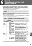
1
Tachometer
®
Installation and Operation Instructions
RPM x 1000
V DO
VDO
Instruments
Winchester, Virginia USA
THE INSTRUCTIONS FOR INSTALLATION AND ELECTRICAL WIRING FOR THESE TACHOMETERS FOLLOW. USE IS RESTRICTED TO 12 VOLT NEGATIVE GROUND ELECTRICAL SYSTEMS.
Tachometer Installation
Parts List
Item
1.
2.
3.
Description
Quantity
Tachometer
Decals, 2 x 4 (not contingency decals)
Posi-Lock Connectors
Installing the tachometer is a three-step process.
1
2
6
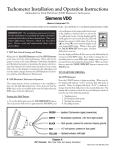
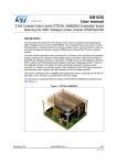
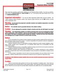
1. Program the Tachometer
Your Xtreme tachometer is factory programmed for an eight
cylinder engine. For other applications the selector switches
must be set according to Diagram A.
Optional Items Which May Be Needed:
Remote Keypad Cable, 6 #240 207
Flush Dash Mounting Bracket #240 104
On-Dash Mounting Bracket #240 103
CAUTION: Read these instructions thoroughly before making installation. Always wear safety glasses, and always disconnect the battery ground before making any electrical connections. If in doubt,
please contact your dealer or VDO Instruments at (540) 665-2428.
·
Remove the 4 cap nuts, lockwashers and rear cover.
·
Find your application in Diagram A and set the
switches accordingly.
·
Replace the rear cover, lockwashers and cap nuts.
DO NOT OVERTIGHTEN!
5HDU &RYHU
s
RECALL
&DS 1XW
TACH
t
START
.H\SDG
6KLIW /LJKW
'LJLWDO 'LVSOD\
7\SH %XOE
6(/(&725 6:,7&+ 6(77,1*6
6HOHFWRU 6ZLWFK
7DFKRPHWHU %DFN
UHDU FRYHU UHPRYHG
&</,1'(5 6(/(&7,21
6:,7&+ 6(77,1*6
&</,1'(56
F\OLQGHU OHJHQGV FDUV PRWRUF\FOH HQJLQHV
RQ
RQ
F\OLQGHU
F\OLQGHU
·V RQ
F\OLQGHU
RQ
F\OLQGHU
·V RQ
·V RQ
F\OLQGHU
·V RQ F\OLQGHU RU SROH VQRZPRELOH RXWERDUG HQJLQHV
Diagram A
Dimensions and Selector Switch Settings
P/N 0 515 010 482
Rev. 03/00
&ROXPQ0RXQW
2Q'DVK
9^4QcX
5ROO%DU
0RXQW
8QGHU'DVK
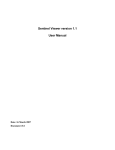
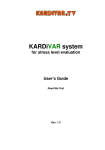
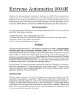
Diagram B
Possible mounting locations for the Extreme Tachometer
2. Mounting the Tachometer
Your Xtreme tachometer can be mounted almost
anywhere. Several suggestions are illustrated in Diagram B.
Some installation techniques may require optional
accessories, cutting, or drilling new holes.
MOUNTING NOTES:
·
The most common mounting location is on the steering
column or roll cage using a band clamp and the
included short mounting bracket.
·
For mounting in the dash, optional flush mounting
bracket [P/N 240 104] is recommended. The rear
cover may also be used as a mounting clamp for in
dash mounting.
·
For mounting on top of the dash, optional longer
mounting bracket [P/N 240 103] is recommended.
REMOTE KEYPAD MOUNTING:
·
Remove the four cap nuts, lockwashers and rear cover.
·
Pull the keypad cable connector straight out from the
back of the tachometer.
·
Remove the two hex bolts, keypad and bracket from
the tachometer.
·
Mount the keypad bracket in the new location.
·
Connect optional extension cable [P/N 240 207]
between the keypad cable connector and the
connector at the rear of the tachometer.
·
Replace the rear cover, lockwashers and cap nuts.
DO NOT OVERTIGHTEN!
MOUNTING CAUTIONS:
·
·
Make sure your Xtreme Tachometer does not rest
against any glass, windshield A pillars, or any roll cage
tubes.
VDO does not recommend mounting your Xtreme
Tachometer close to other electrical components or
their associated wiring. For example, the ignition
system box, the ignition coil, electric fuel pump, etc.
3. Wiring the Tachometer
·
Turn off the ignition and disconnect the negative
terminal from the battery post if you havent already
done so.
·
Wire the tachometer to the vehicle as shown in
either Diagram C * or Diagram D *.
* Refer to your vehicles owner/service manual or the
aftermarket ignition manufacturers instructions for
the recommended place to tap the signal. Typical
examples are shown in the table below.
IGNITION
TYPE
CONNECTIONS
Standard
points / breakerless
negative terminal on coil
CD
points
points connection to CD box
breakerless
positive terminal on coil
MSD, ACCEL,
MALLORY, DDIS
(distributorless),etc.
Tach output terminal on ignition
box, or points connection to
ignition box, or negative coil
Electronic
·
Be sure to connect the tachometer wires using the
supplied Posi-Lock Connectors. Use them as shown
in the following illustration:
CdbY`gYbUU^TcQR_ed
9^cUbdUQSXgYbUY^d_Q]Q\UU^T
Uh`_cY^W_^\iRQbUgYbU
8Q^TdYWXdU^]Q\UU^Tc
Y^d_U^Tc_VRQbbU\
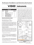
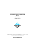
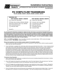
%/8(
/LQHORFN 7UDQVEUDNH RU 'HOD\ %R[ RXWSXW
*5((1
,JQLWLRQ 7DFKRPHWHU VLJQDO FRQQHFWLRQ
:+,7(
YROW ,OOXPLQDWLRQ FRQQHFW WR OLJKW VZLWFK
%/$&.
7DFK JURXQG FRQQHFW WR FRPPRQ FKDVVLV JURXQG
5('
YROW SRZHU FRQQHFW WR IXVH SDQHO
<(//2:
([WHUQDO VKLIW OLJKW
Diagram C
General Wiring Information
<HOORZ:LUH
$Q\W\SHRI:$51,1*/,*+7
VXFKDV
7R83&([WHUPDO6KLIW/LJKW
9'23DUW
,I\RX¯UHQRWXVLQJDVKLIWOLJKW
386+%87721
%OXH
326,7,9(
6285&(
*5281'
GRQ¯WFRQQHFWWKLVWRDQ\WKLQJ
:LU
H
:KLWH:LUH
WROLJKWVZLWFK
%ODFN:LUH
ALL FUNCTIONS OF
THE TACH REMAIN
THE SAME AS OUTLINED IN THE TEXT OF
THIS INSTRUCTION
SHEET.
*UHHQ:LUH
WRWDFKVLJQDOSLFNXS
5HG:LUH
Diagram D
Xtreme Wiring for Circle Track/Road Racing Applications
Xtreme Tachometer Operation
1. Setting the Record Length
· Press and hold in TACH/RPM SET
while you turn on the power.
·
Press the up (s) arrow to change the
record time to 360 seconds, or the down
(t) arrow to change back to 90 seconds
[factory setting is for 90 sec.]. A dot
appears in the Digital Display when you
record and play back in the 360 second mode. Press
TACH/RPM SET to return to the tach mode.
',*,7$/ /(' ',63/$<
6HFRQG
5HFRUG ,QGLFDWRU
2. Setting the Shift Points
·
·
Press the up (s) arrow or the down (t) arrow until
the display reads your desired RPM value.
·
Press TACH/RPM SET again to save this value.
The display will show S-2 briefly, then it will show
the second shift RPM value.
6
NOTE: If only one shift point is required, set the second
and third shift point values to the same value as the
first shift point value. If two shift points are required,
set the third value the same as the second.
Repeat the above procedure to set or change your
desired second shift RPM value.
·
Press the TACH/RPM SET button while in normal
[tach] mode. The tach pointer will move to 3000 RPM
[approx.] and a dot will appear in the display to indicate
RPM SET mode. S-1 appears in the display itself
to indicate you are about to set shift point #1.
6
530 6HW
,QGLFDWRU
530 6HW
,QGLFDWRU
Press TACH/RPM SET again to save this value.
The display will now show S-3 briefly, then it will
show the third shift RPM value, if there is one.
6
530 6HW
,QGLFDWRU
Repeat the above procedure to set your desired third
shift RPM value.
·
Press TACH/RPM SET again to save this value and
return to the normal [tachometer] mode.
3. To Record A Run
Press the START button [or activate
LINE LOCK / TRANSBRAKE if
connected]. Once recording has begun,
the display will show the number of the
run being stored (#1 to #4).
·
If four runs are stored and the
START button is pushed [or LINE
LOCK / TRANSBRAKE is activated], the display
will read
The display will now show the number of the last run
recorded (1, 2, 3 or 4). If the number of the run
showing on the display is not the run you want to play
back, quickly [within two seconds] press RECALL
again (and again and again, etc.) to cycle through the
run numbers until you get to the one you want to play
back. Playback begins after 2 seconds.
·
To rewind or fast forward at any time during playback,
press (t) [rewind] or (s) [fast forward]. Fast
forward will occur at double time if real-time [1:1]
playback is selected. Fast forward will occur in real
time if slow motion playback is selected.
·
If the recording was activated using LINE LOCK or
TRANS BRAKE, the display will count down to the
point of last release to show launch. If FAST
FORWARD or REWIND is pressed, the display will
pause at the point of each line lock release. When the
replay is finished, the display will read END and
show the peak RPM achieved.
æ
·
·
IXOO
If a driver has already started a run when he presses
START and discovers the memory full, he has five
seconds to press START again to clear the memory
and record his current run. If the driver chooses not
to clear memory at this time, the Xtreme Tachometer
will return to normal mode in 5 seconds. He can wait
until the end of his run to clear the memory as outlined
in Step 5.
·
To stop recording, either press TACH/RPM SET
or turn off the power. In any case, recording will stop
automatically after the elapse of the
preset time: 90 or 360 seconds.
Press the RECALL button.
The display will show the default 1:3
[slow motion] setting. If you want to
play back the run in real time (1:1),
quickly [within two seconds] press
RECALL again.
HELPFUL HINTS
5. To Clear the Memory
·
Press (s) and (t) at the same time and hold in the
buttons while turning on the power.
The display
will flash
twice:
4. To Recall A Run
·
NOTE: RECALL will not function if the input is above
2000 RPM.
When it is finished flashing the memory will be clear
and ready for a new test session.
TO AVOID ERRATIC TACH READINGS DURING REPLAY:
• Check plug wires. If they’re more than a season old,
replace them.
• Coil wires begin fatiguing faster than other
wires...some at 60 passes or ½ season. Check
them.
• Are the crank trigger wires too close to the coil wire?
• Is the spark plug gap more than .040? Gaps of more
than .040 will cause the wires to fatigue faster.
VDO Limited Warranty
VDO North America, LLC. warrants all merchandise against defects in factory workmanship and materials for a period of 24 months after purchase. This warranty
applies to the first retail purchaser and covers only those products exposed to
normal use or service. Provisions of this warranty shall not apply to a VDO product
used for a purpose for which it is not designed, or which has been altered in any
way that would be detrimental to the performance or life of the product, or misapplication, misuse, negligence or accident. On any part or product found to be
defective after examination by VDO North America, VDO North America will only
VDO Instruments
repair or replace the merchandise through the original selling dealer or on a direct
basis. VDO North America assumes no responsibility for diagnosis, removal and/
or installation labor, loss of vehicle use, loss of time, inconvenience or any other
consequential expenses. The warranties herin are in lieu of any other expressed or
implied warranties, including any implied warranty of merchantability or fitness,
and any other obligation on the part of VDO North America, or selling dealer.
(NOTE: This is a Limited Warranty as defined by the Magnuson-Moss Warranty Act of 1975.)
. 188 Brooke Rd. . P.O. Box 2897 . Winchester, VA 22603 . Phone: 540-665-2428