1
Plexus C/1000D
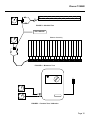
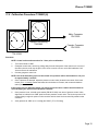
12.4.3 Attach unit to test gauge (See FIGURE 5), set comfort control to “MIN”. The unit should provide a
pressure of 21 ± 3 mmHg to one port. Pressure should alternate between gauges approximately
every 2.5 minutes. If unit does not achieve pressure attempt calibration (See 17.0), replace pump
if pressures can not meet calibration specs.
If no problem is detected continue with test procedure.
12.5
Timing Motor:
12.5.1 Units with float function: Verify that power in being supplied to both the pump and timing motor,
using a voltmeter. Place meter to read VAC, and touch both terminals marked as motor on the
PCB. Voltage should read 120 or 230 VAC, depending on the line voltage. If no voltage is
detected replace PCB.
If no problem is detected continue with test procedure.
12.5.2 For standard units: Check voltage by touching the two outside terminals on the switch with
voltmeter probes. Readings should match line voltage being supplied (110 or 220). If reading is
less than supplied voltage check switch and fuse.
12.5.3 Visually check the motor and verify that it is turning. If motor is not rotating, replace motor.
If no problem is detected continue with test procedure.
12.6
Control Valve:
12.6.1 Attach unit to test gauge (See FIGURE 5), set comfort control to “MAX”, pressure should reach
75 ± 15 mmHg. If unit is out of spec. Refer to calibration procedure.
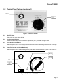
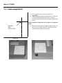
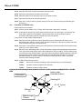
12.6.2 If unit fails pressure test, replace valve (See FIGURE 6, and 7):
12.6.2.1
Pull knob from front of enclosure.
12.6.2.2
Take off retainer attached to valve at base of valve seat.
12.6.2.3
Push the valve through to the front of the unit, and pull the knob and valve out.
12.6.2.4
Install new valve (PN 10137). Insure that retainer is fully seated, and that valve body
does not rotate when stem is turned.
12.6.2.5
Set pressure minimum to 21 ± 2 mmHg by turning valve stem.
12.6.2.6
Install knob onto into recess on front of enclosure with the indicator at the “MIN’
position.
12.6.2.7
Turn knob to “MAX”, verify the indicator stops at “MAX” position, and pressure reads
75 ± 15 mmHg
12.6.3 If comfort knob continually spins, return unit for repair.
If no problem is detected continue with test procedure.
12.7
Fuse:
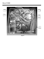
12.7.1 Open the unit and check the fuses.
12.7.2 Check fuse by setting the voltmeter for continuity check. Touch one end of the fuse with one
probe and the other end with the other probe. If the fuse is bad, the meter will not detect and
resistance and will not produce a continuous beeping sound. The fuse is good if a resistance
across it is detected and a continuous beeping sound is heard.
If no problem is detected continue with test procedure.
12.8
On/Off Switch:
12.8.1 Make sure that the unit is not plugged in.
12.8.2 Remove all three leads attached to the switch.
12.8.3 Push switch out of the panel while pushing in the snaps on the side of the switch.
Page 14