1
WRSCCJ
~
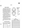
SUGGESTED
UNIT
PIECE N O , - - - - - SERIAL NO. _ _ _ __
...
..
..
STEP NO .
Max. & Min.Length
of Long and Short
Code Steps,
measured in
Cycles, at 70° F.
with Local Batt.
16-18 Volts
(Freq. = 60 Cycles)
(See Notes Below)
Location of Unit
1
Short
.(Ind.Code)
8.5
12.5
Long
(Control Code)
21
28
2
3
4
Short
Short
Short Short
6
7
Short Short
8
9
Short
Short
FOR
11
10
Short Short
RECORDING
12
13
14
Short Short Short
TIMING
15
Short
DATA
16
Between
Consecutive Codes
'O
QI
c:
()
<ti
' -·:_.~:5·
4.5
6.5___ 6.5
Long Long
18
24
5
FORM
20
26
4.5
6.5
Long
18
24
4.5
6.5
Long
20
26
4.5
6.5
Long
18
24
4.5
6.5
Long
20
26
4.5
6.5
Long
18
24
4.5
6.5
Long
19
24
4.5
6.5
Long
17
22
4.5
6.5
Long
19
24
4.5
6.5
Long
17
22
4.5
6.5
Long
19
24
4.5
6.5
Long
17
22
4.5
6.5
Long
l9
24
Control Codes
57-61
Indication Codes
Without
SS
59-63
With
SS
75-85
i::i.
0
..... ,.....
0. <ti~
.-41
(I)
QI
()
<ti () 0
I-<
c:
:::>
t~
QI
~
A
QI
~
A
Q.>
c:
rJl
(I)
<ti .....
..:I~
QI
'a
-= 0.2!
QI
~
Q
REMARKS
>,
ix:i
(I)
~·:::..:I
=== s...
::I
~
!01
QI
.8
rJl
....
E-<
{Such as unusual conditons)
c:
QI
~
I
E-<
cl1
~
Measured length of code steps
I
I
NOTES
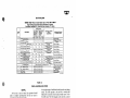
1. All tapes for field tests may be taken at the office. (To obtain timing with SS relay, someone must be
present at the field location to initiate consecutive indication codes. However, since the SS relay
timing is not critical, it need not necessarily be checked every time that field tests are made).
2. Specification limits for allowable length of each code step are shown at the top of the column for the
code step to which they apply. These limits are specified in terms of cycles (60 cycles = 1 second)
and based on temperature of 70° F. When making tests, actual temperature of unit being tested should
be recorded. Timing data should be corrected for temperature in accordance with table in Instruction
Pamphlet U-5122 , when actual temperature of unit differs from 70° F. by morP. than 35° F.
When frequency used in obtaining timing data is other than 60 cycles per second, specified timing values
should be evaluated in terms of the new frequency as follows:
Specified timing values X new fr:iuency
i
Values shown are those obtained when unit is in service on a D.C. cocje
line or when timing is measured at field. For timing of field units
(measured at office) for carrier controlled sections see proper table
under Field Maintenance Tests.
3. If the timing of a particular code step is within 1/2 cycle of the limits, take a second tape and record
the longest count.
--
5122,p.17/18