1
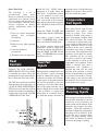
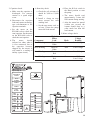
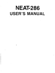
NOVUS 3000 STANDARD ELECTRICAL CONTROLS INSTALLATION AND SERVICE MANUAL NOTE! To the installer: Please make sure you provide this manual to the owner of the equipment or to the responsible party who maintains the system. Item # H-03-519 | Part # 5625-519-1 | © 2012 Pentair Pump Group, Inc. | 11/02/12 General Information Thank you for purchasing your Hydromatic® Novus Control Panel. To help ensure years of trouble-free operation, please read the following manual carefully. Before Operation: Read the following in structions caref ull y. Reasonable care and safe meth ods should be practiced. Check local codes and requirements before installation. Attention: This manual contains important information for the safe use of this product. Read this manual completely before using this product and refer to it often for con tin ued safe product use. DO NOT THROW AWAY OR LOSE THIS MAN U AL. Keep it in a safe place so that you may refer to it often. CALIFORNIA PROPOSITION 65 WARNING: This product and related accessories contain chemicals known to the State of California to cause cancer, birth defects or other reproductive harm. Introduction The model NOVUS 3000 is a float switch based dual pump controller intended primarily for wastewater lift stations and other pump-down applications. It has inputs for five normally open float switches and sensor inputs for the seal fail and temperature fail sensors normally found in submersible pumps. The controller has indicator lamps and 2 test push button switches on each of the float inputs as well as an indicator that will illuminate if the floats do not close in the correct order. The controller has built-in alternation and a three position switch to select automatic alternation or to select between pump 1 and pump 2 if alternation is off. The controller has disable inputs for each of the pumps. The controller has built-in support for an alarm horn with inputs for an external mute button and also a mute button on the controller front panel. There are two alarm outputs, one for the high alarm and one for the low alarm. These output relays can be set up to cycle on and off during an alarm to support a blinking panel alarm light. The controller has five output relays. Two are for the two pumps, one each for the high and low level alarms, and one to drive the horn. The controller has indicator lights and external relay drivers for the following conditions: floats out of order, seal fail for pumps 1 and 2, temperature fail for pumps 1 and 2, and pump disabled for pumps 1 and 2. Unpacking Panel: Remove panel from carton. When unpacking unit, check for con c ealed damage. Claims for damage must be made at the receiving end through the delivery carrier. Dam age cannot be processed from the factory. Power Supply WARNING: Do not attempt to wire this control box unless you have a good working knowledge of electricity and are familiar with the state and local codes. If you are in doubt about anything, contact a qualified electrician. Do not attempt to operate this unit on any other voltage or power distribution other than for which it was originally designed (check nameplate). Failure to comply with this will result in the immediate cancellation of all warranties and claims. It is advisable to put the panel on its own circuit using a circuit breaker adequately sized to protect the pump(s). Check state and local codes for the correct wire size and circuit protection to use. The wire should be sized large enough to handle the full load current of the pump(s) you are operating and any voltage drop that might occur due to long service runs. Run power supply lines to the control box and secure (knockouts are not supplied in this box). Select a convenient location on the bottom to enter the box with the power supply. Cut a hole with a chassis punch. Caution should be taken not to get metal chips in the components while cutting hole. After the hole is cut, any metal particles must be removed from the box. Failure to do so may result in premature component failure. Connect incoming power to the terminal blocks labeled L1, L2, L3, and all necessary ground wires to the ground lug at the bottom of the box. The ground lug should be fastened to a good driven earth ground by one of the methods described in the National Electric Code. NEC does not permit using ground as a current-carrying conductor, therefore a neutral must be provided for 115 volt 1 phase, 208 volt 1 phase, 230 volt 1 phase, or 208 volt 3 phase systems. WARNING: Before handling these pumps and controls, always disconnect the power first. Do not smoke or use sparkable electrical devices or flames in a septic (gaseous) or possible septic sump. Electrical Connections: The contractor must conform to the latest requirements of the National Electrical Code. All conduit and ca bles shall be in accordance with NEC Code NFPA #70. To maintain UL and CSA ENCL rating, use the same type UL and CSA weatherproof conduit hubs when connecting to this enclosure. Prior to conducting any installation, repair or service with regard to the control panel, refer to the schematic appropriate for that panel. The schematic will provide guidance with regard to the terminal block connections. CAUTION: A nonmetallic enclosure does not provide grounding conduit connections. Use grounding bush ing and jumper wires. Make the Following Electrical Connections: a.Connect the pump leads to the control panel. If pump is single phase and the panel has start capacitor, start relay and run capacitor, it is critical that the pump leads be connected properly. The White, Black, and Red pump leads must be connected to the appropriate terminals as direct ed by the panel schematic and the label on the back panel below the terminals. b.Connect the pump heat sensor and seal failure leads (if available on the pump) to the appropriate terminal blocks in the control panel. c.Connect all the float control leads or 4-20mA leads to the appropriate panel terminals. Contractor must be very careful in locating the floats at the proper elevations. The maximum dis tance from the control panel to the floats is the lesser of l00 feet, or the maximum distance recommended for the pump. d.Before connecting power to the control panel, make sure all control switches (e.g. H-O-A switch) and protective devices (e.g. breakers) are in the Off position. Now connect power to the terminal block or the circuit breaker as directed by the schematic. e. Control panel must be grounded properly per NEC and/or local codes. To facilitate this, a ground lug is provided on the control panel. Operation The NOVUS 3000 uses five normally open float switches for level sensing. When the tank is empty all of the floats are open. The lowest float is the low alarm float. If it is not used the low float input should be shorted with a jumper. When the tank is empty the controller will be in the low alarm condition. On rising water, when the level is high enough to close the low float switch then the low alarm will go off. As the level rises the off float will close and then the lead float will close. When this happens the pump controller will call for the lead pump. Which pump is the lead, will be determined by the alternator. If the alternator is set for pump 1, then pump 1 will be called. If the alternator is set for pump 2, then it will be called. If the alternator is set in the on position, then for each pump cycle the lead pump will change. If one of the pumps has an existing leak failure, then the other pump will be called as the lead. If any pump has existing temperature failure or is disabled, then that pump will not be called. If the lead pump lowers the water level far enough to open both the lead and off floats, then the lead pump will be turned off and the lead pump changed if alternation is on. If the water level continues to rise and closes the lag pump, then the lag pump will be called. If the level drops enough to open the lag, lead, and off floats, then the two pumps will be turned off. When both pumps are turned off there is a 4 second delay between the first and second pump turning off. If the water level continues to rise and closes the high alarm float, then the high alarm condition will be set. This will cause the high alarm relay and light to come on. This alarm condition will clear when the level is low enough to open the high float. Any time a pump is started an internal timer is started which will prevent the other pump from starting for a period of time which is selected by one of the option switches on the bottom of the controller. This time can be either 6 or 12 seconds. The controller has three pairs of inputs for setting pump related alarms or faults. Start-up Operation 1. Check junction box for moisture. Moisture may cause chattering of relays/contactors. 2.If pump is single phase with start capacitor, start relay and run capacitor in panel. Check that pump White, 3 Black, and Red pow er wires are connected to panel correctly. 3.WARNING! Live voltage can kill! Check incoming power volt age to make sure that it is correct for panel and pump model. 4.Energize control panel. (Turn on power to panel.) 5. Check overload relay and verify reset mode (if overload is supplied). 6.WARNING! Live voltage can kill! Check voltage to the panel and at secondary of control trans form er using a voltmeter. If no transformer is supplied, check voltage at the circuit breakers. 7.With H-O-A switch in hand, check discharge to verify the pump is run ning. Check for flow. On three phase power, check to see if each pump has proper rotation. Wrong rotation will give low flow. 8. Check full load current with amp probe and compare it with the nameplate rating. On three phase pumps, check all three phases. On single phase pumps, check black pump lead. 9.Check operation of start relay, if supplied on single phase panels, per procedure in Item #7 of Maintenance Instructions. 10.With H-O-A switch in Auto, check float operation and response to control panel to the float operation. For sequence of operation, refer to design specification. 11.Make sure H-O-A switch is left in the Auto position after start-up is completed. 4 Pump Start-Up: Refer to pump Installation and Service Manual. Pump Maintenance WARNING: Before handling these pumps and controls, always disc onn ect the power first. Do not smoke or use sparkable electrical devices or flames in a septic (gaseous) or possible septic sump. The maintenance schedule will vary with operating and environmental conditions. It will also vary with the specific type of control supplied. The list herein is a guide only. 1. Exercise breaker through one cycle. Be careful not to overexercise as the break er is not a switch ing device. Excessive operations tend to affect the trip curve of the breaker. 2.Check contactors and relays for excessive humming. This can be accomplished by turning pumps on and off in the Hand mode with the H-O-A switch. 3. Check pump run light(s) by run ning pump(s) in Hand mode. Check bulb(s) in any other light(s). 4.With the power off, check continuity of all control fuses. 5. Check voltage at primary and sec ond ary of control transformer. 6. Check the load amps. pump full 7.For 1 phase panels with start circuit, about 5 seconds after the pump starts check the voltage from terminal 1 to terminal 2 on the start relay to be sure that the relay has operated. The voltage from terminal 1 to terminal 2 on the start relay must exceed 10 VAC. For some pumps the voltage may exceed 400 VAC. If after 5 seconds the voltage from terminal 1 to terminal 2 on the start relay does not exceed 10 VAC, stop the pump as the start capacitor may be damaged in about 15 seconds. If the start relay is not operating, check the pump and the system voltage to be sure that they match. Check the power wiring to ensure that the pump is connected properly. Start the pump once more and check that the voltage from the terminal for the black wire to the white wire is within system tolerance. Call for help if you cannot resolve the problem. 8. Check junction boxes for moisture. Moisture may cause chattering of relays and contactors. 9.Check for moisture inside control panel enclosure. Moisture can cause damage to electrical components. Check door gasket for proper seal. 10.Check labels to verify they have not been damaged. 11.Lubricate enclosure hinges. 12. Pull floats and check for proper operation and ensure there is no foreign buildup on them. Spare Parts List: The following is a list of recommended spare parts. However, conditions of service vary significantly and a general list may not in its entirety be applicable to a given installation. The user should ex er cise judgment in defining specific re quire ments based on this guide. 1. Fuses for control transformer primary and secondary. (If required) 2.Contactor. 3.Bulbs for any light requiring a bulb. 4.Control transformer. (If required) 5.Alternator relay. (If required) Float Controls Optional: The LOW WATER / REDUNDANT OFF float should be installed just above where the pump begins to ingest air normally; this is about the top of the volute. The OFF float should be installed about halfway down the pump. If a LOW WATER / REDUNDANT OFF float is used, then the off float should be installed a minimum of 4 inches above the LOW WATER / REDUNDANT OFF float. Install the ON / LEAD floats a lag pump and its seal fail lamp and minimum of 4 inches above the output are activated. The seal fail OFF float. If additional volume does not disable the pump. is to be pumped on each cycle or if the pump running time for Temperature each cycle needs to be increased, then increase the distance from the Fail Inputs ON / LEAD float to the OFF float as needed. Each pump has an input for the Install the HIGH WATER float temperature fail sensor often 4 inches above the ON / LEAD float. found in pumps. This sensor should be shorted if the pump is For duplex systems install the good. If the pump overheats, then LAG / OVERRIDE float 4 inches this sensor will open. The sensor is connected to ground and to the above the HIGH WATER float. sensor input for that pump. If the On duplex systems where both pump controller detects an open pumps have to run on a daily basis condition in the sensor, then the to keep up with the incoming flow, temperature fail lamp and output then the HIGH WATER and the are activated. The temperature fail LAG / OVERRIDE float position condition will disable the pump. The controller can be set using should be reversed. an option switch on the bottom of the controller to latch up the Seal Fail temperature fail condition. If this option is selected, then once a Inputs temperature fail condition is detected the fault will not clear Each pump has an input for the seal until the fault condition is cleared fail (moisture) sensor commonly and the reset push button is pushed found in submersible pumps. The (or external reset input is closed). controller measures the resistance If this option is not selected, then of the sensor. In normal operation the fault will clear when the sensor the seal fail condition is set if the in the pump closes again. resistance is less than 2000 ohms. One of the option switches can be used to change this to set the alarm Disable / Pump if the resistance is greater than Running Inputs 2000 ohms. If a seal fail alarm is set, then that pump is demoted to Each pump has an input which has two possible functions. If the fail to start test is not activated by an option switch on the bottom of the controller, these inputs are pump disabled. Under this condition, if this input is shorted to ground, then that pump will be disabled. If the fail to start test is activated these inputs are pump running inputs and should be shorted to ground whenever the pump is running. 5 Fail To Start Test If the reset button is pushed or the external reset/mute input is activated, then the horn relay is cleared. If the horn is muted, then it will not reactivate until the alarm condition is cleared and another starts. SW6 – When this switch is set, the time between pump starts and the delay for the fail to start test is 12 seconds instead of 6 seconds. If the fail to start test is activated Fault (using the option switches on the bottom of the controller), then the Outputs follow sequence is used each time 2.If the common alarm option is selected, then this relay will a pump is called: be activated when any of the There are seven fault lamps with following conditions exist: 1.When a pump is called a timer corresponding driver outputs. They is started. are used to display the following • High alarm fault conditions: 2. After a start-up time has • Low alarm expired (set by switch 6), the 1.Floats out of order pump running input is checked. • Pump temperature failure 2.Pump 1 seal fail If the pump is not running • Pump disabled by fail to at the end of the time, then a start test 3.Pump 2 seal fail pump fail to start condition is set and the pump is disabled. This common alarm condition can 4.Pump 1 temperature fail The pump will remain disabled be used to drive an alarm light, until the reset button is pushed telephone dialer, or telemetry 5.Pump 2 temperature fail or until the external reset input system. 6.Pump 1 disabled is activated. 7.Pump 2 disabled Alarm Relay Outputs The controller has two relays for level alarm. Option switch 5 can be used to cause these relays to cycle on and off. This is useful to provide blinking on the external alarm lights. Auxiliary Relay Option Switches Each of these has a corresponding relay drive output. These outputs are designed to drive the coil of a 12VDC relay external to the There are six switches on the back controller. A source of 12VDC of the controller which select is also provided. To use these several different options. outputs, one side of the relay coil is connected to 12VDC and the SW1 – When this switch is set, the other coil connection is connected fail to start test is enabled. to the driver output. SW2 – When this switch is set, the temperature fail condition is latched up until reset. Specifications SW3 – When this switch is set, the seal fail input is inverted (open is Float and Sensor Inputs There is one relay that can have fault). either of two functions selected by There are five float inputs; two seal option switch 4: SW4 – When this switch is set, the fail sensor inputs, two temperature fail inputs, and two disable inputs. 1.If the horn option is selected, aux relay is the common alarm. If They use current limiting resistors, then this relay can be used to it is not set, then the aux relay is filter capacitors and Zener diodes drive an external horn or bell. the horn output. for transient protection. They also Whenever either a high or have both hardware and software low alarm condition starts, the SW5 – When this switch is set, filters on these inputs to improve relay is activated (closed). If the low and high alarm relays will immunity from noise. They have the alarm condition is cleared, cycle, causing a lamp blink. the following specifications: then the relay is also cleared. 6 Short Circuit Current less than 2 Ma. Open Circuit Voltage 5.0 VDC Mute / Reset Input The mute / reset input is intended for use with a momentary push button switch mounted on the dead front or on the side of the enclosure. It has the following specifications: Storage Temperature –20° C to e.Check wiring of pump to con trol panel. It should 65° C agree with the schematic. 0% to 95% relative humidity, non f. Check contactor coil condensing resistance. Fault Driver Outputs 2. Pump does not run in Auto position. The controller has seven open drain FET driver outputs for driving a. Check items (a.) through (f.) external relays, lights, telephone per Item #1 above. dialers, or remote terminal units. The outputs short to ground when b.Floats may be miswired to control panel. Check float Short Circuit Current less than 2 Ma. activated and have the following type (N.O. or N.C.) and specifications: hook up by referring to the Open Circuit Voltage 5.0 VDC schematic. If the start and Maximum voltage +12VDC stop floats are hooked in Relay Outputs reverse, pump will short There are five relays which are Minimum voltage 0.0 VDC cycle and will not pump the used for pumps and alarms. All of level down. them except the low alarm relay Maximum continuous sink current +0.4 amps are form A (SPST) relays. The 1. Is water level in the low alarm is a form C (SPDT) sys tem high enough to relay. They have the following Maximum on resistance 2 ohms activate the floats? specifications: 2.If there is enough water Pump in the system (with the Maximum current at 120 VAC, power turned off), mark 7 amps with a resistive load Troubleshooting and disconnect the off and on floats. Next, Maximum voltage 140 VAC install jumper wires in WARNING: Before handling the terminal blocks for off these pumps and controls, always Power Inputs and on floats. Turn power dis con nect the power first. Do The controller is designed to not smoke or use sparkable back on, put H-O-A run on 120 VAC control power. electrical devices or flames in switch in Auto and see if It is internally fused at 1 amp a septic (gas pump runs. eous) or possible and transient protected with a septic sump. 3.If pump runs with jumper, MOV transient protector. It uses problem is with floats. transformer isolation and internal 1. Pump does not run in Remove jumpers and current limited voltage regulators. Hand position. troubleshoot floats with It has the following specifications: a. Check pump circuit breaker ohmmeter. and control fuse for tripping Input Voltage 120 VAC ± 10% 4.If pump does not run in or blown condition. 50 to 70 Hz. Auto mode with jumpers, b. Check incoming power check Auto circuit wiring Maximum Current 0.4 amps volt a ge and control in panel. circuit voltage. Operating and Storage 3.Pump runs, but run light Temperature Range c. Check overload relay to see does not energize. if it is tripped. Reset relay Operating Temperature –10° C to move light and check if tripped and check pump a.Re 60° C with an ohmmeter. current with ammmeter. 0% to 95% relative humidity, non- d.With the power off, check b. Check run light wiring. condensing motor heat sensor continuity. 7 Pump Troubleshooting 6.Short cycling pump. a. Check float controls. 7.Run light stays on. 5.Move each lead to the next terminal (1 to 3, 2 to 1, 3 to 2). a.Selector switch may be in the 6. Again read the amperage of Hand position. each lead. 8. Nuisance tripping of 7.If the unbalance moves with a. On three phase only, over l oad on motor starters or pump rotation may be wrong. the motor leads, the un balance circuit breakers. Wiring of pump to con trol is caused by the mo tor. If pan el may be re verse a.Check pump amp draw with the unbalance remains with the sequenced. terminals, the un bal ance is in amp probe and compare to the pow e r supply. nameplate amps on pump. b.Impeller may be dragging 4.Pump runs but does not pump down the wet well. in volute due to sol ids. High am per age draw would identify this. c.Refer to the pump manual for other possibilities such as closed discharge gate valve, etc. 5. Severe humming/chattering of contactors and control relays. a.There may be low voltage. Check voltage at primary and secondary of control transformer us ing a volt me ter. This low voltage condition may cause severe chattering and burnout of contactors and relays. b.Contactor may have dust around magnet of coil struc ture. Dry or clean as required. c. Check voltage to the control panel. Contactors require a minimum of 85% of full volt age to pull in without chatter. If the problem is a re cur ring one, measure voltage with recorder on a 24 hour basis. 4. Again read the amperage of each lead. b.The impeller may be locked 8.If the current unbalance exceeds five percent, nuisance tripping or up due to excessive debris or excessive heating will result. solids. c. Possible motor failure (fault in 9.Connect leads for the lowest percent of current unbalance. windings). Connections and start d.Pump may be miswired to f. components. Single phase terminal block. only. e. Voltage and current unbalance. Three phase 1.Disconnect all power from the panel before making only. Voltage unbalance on these checks. three phase power sources can cause motor current to 2. Motor winding resistance become unbalanced and readings. exces sive heating will Disconnect all three re sult. Trip ping of the a. motor leads from panel over load protectors and terminal blocks. premature motor failures can be expected if the current unbalance exceeds b.Using a volt-ohmmeter, with the scale set on RX1, measure five percent. the resistance be tween the leads with the chart. Percent Maximum Current Current = Difference from x 100 Unbalance Average Current _______________ Average Current Typical MotorResistance WindingLeads Reading To determine if motor current Main Black to unbalance is a function of the motor White or the power supply: Start Black to Next RedLowest (Middle) 1. Label the leads and the d.Make sure the floats are terminals 1, 2, and 3 respectively. locat ed away from any Both turbulence. 2.Record the amperage for each lead. e.Dry out the junction box (if furnished); moisture 3.Move each lead to the next terminal (1 to 2, 2 to 3, in the junction box may 3 to 1). cause relays to energize intermittently. 8 Lowest White to Highest Red (Main & Start) 4.Start relay check. 3.Capacitor check. d.Place the H-O-A switch in the Hand position to start the pump. a.Make sure the capacitor is a.Check the coil resistance It should be 3,000 to 15,000 dis charged. Use extreme e.The meter should read ohms. caution as a spark might approximately 2 times full occur. b.Install a clamp on amp load current during starting. meter around the start b. Disconnect the capacitor f.After the motor has started winding lead. leads and connect an analog(within one sec ond) the type volt-ohmmeter to the c.Set the amp meter scale to cur rent should drop to a capacitor terminals. at least 2 times the pump value much less than full motor full load current. c. Set the meter on the load current. RX1,000 scale to check the 5.Motor voltage check: start capacit or. Set the meter on the RX10,000 scale to Typical check the run capacitor. MotorVoltage d. The meter should Component Lead ModeReading indicate low ohms when it Main Winding Black to Start Line Voltage is first connected, but as White the capacitor becomes Black to Run Line Voltage charged (by the meter), it Main Winding will return to a reading of White Start Winding Black to Start Line Voltage infinity (open circuit). Red Start Winding Black to Run 120% Red Line Voltage Duplex Pump Controller ALT AUX RELAY / HORN 1-2 2-1 ALTERNATION HIGH ALARM PUMP 2 PUMP 1 LOW ALARM HIGH FLOAT FLOATS OUT OF ORDER LAG FLOAT PUMP 2 PUMP 1 LEAD FLOAT OFF FLOAT LOW FLOAT PUMP 2 PUMP 1 RESET MUTE PUMP 2 PUMP 1 SEAL FAIL TEMP FAIL DISABLED 9 THIS PAGE INTENTIONALLY LEFT BLANK THIS PAGE INTENTIONALLY LEFT BLANK STANDARD LIMITED WARRANTY Pentair Hydromatic® warrants its products against defects in material and workmanship for a period of 12 months from the date of shipment from Pentair Hydromatic or 18 months from the manufacturing date, whichever occurs first – provided that such products are used in compliance with the requirements of the Pentair Hydromatic catalog and technical manuals for use in pumping raw sewage, municipal wastewater or similar, abrasive-free, noncorrosive liquids. During the warranty period and subject to the conditions set forth, Pentair Hydromatic, at its discretion, will repair or replace to the original user, the parts that prove defective in materials and workmanship. Pentair Hydromatic reserves the right to change or improve its products or any portions thereof without being obligated to provide such a change or improvement for prior sold and/or shipped units. Start-up reports and electrical schematics may be required to support warranty claims. Submit at the time of start up through the Pentair Hydromatic website: http://forms.pentairliterature.com/startupform/startupform.asp?type=h. Warranty is effective only if Pentair Hydromatic authorized control panels are used. All seal fail and heat sensing devices must be hooked up, functional and monitored or this warranty will be void. Pentair Hydromatic will cover only the lower seal and labor thereof for all dual seal pumps. Under no circumstance will Pentair Hydromatic be responsible for the cost of field labor, travel expenses, rented equipment, removal/reinstallation costs or freight expenses to and from the factory or an authorized Pentair Hydromatic service facility. This limited warranty will not apply: (a) to defects or malfunctions resulting from failure to properly install, operate or maintain the unit in accordance with the printed instructions provided; (b) to failures resulting from abuse, accident or negligence; (c) to normal maintenance services and parts used in connection with such service; (d) to units that are not installed in accordance with applicable local codes, ordinances and good trade practices; (e) if the unit is moved from its original installation location; (f) if unit is used for purposes other than for what it is designed and manufactured; (g) to any unit that has been repaired or altered by anyone other than Pentair Hydromatic or an authorized Pentair Hydromatic service provider; (h) to any unit that has been repaired using non factory specified/ OEM parts. Warranty Exclusions: Pentair HYDROMATIC MAKES NO EXPRESS OR IMPLIED WARRANTIES THAT EXTEND BEYOND THE DESCRIPTION ON THE FACE HEREOF. Pentair HYDROMATIC SPECIFICALLY DISCLAIMS THE IMPLIED WARRANTIES OF MERCHANTABILITY AND FITNESS FOR ANY PARTICULAR PURPOSE. Liability Limitation: IN NO EVENT SHALL Pentair HYDROMATIC BE LIABLE OR RESPONSIBLE FOR CONSEQUENTIAL, INCIDENTAL OR SPECIAL DAMAGES RESULTING FROM OR RELATED IN ANY MANNER TO ANY Pentair HYDROMATIC PRODUCT OR PARTS THEREOF. PERSONAL INJURY AND/OR PROPERTY DAMAGE MAY RESULT FROM IMPROPER INSTALLATION. Pentair HYDROMATIC DISCLAIMS ALL LIABILITY, INCLUDING LIABILITY UNDER THIS WARRANTY, FOR IMPROPER INSTALLATION. Pentair HYDROMATIC RECOMMENDS INSTALLATION BY PROFESSIONALS. Some states do not permit some or all of the above warranty limitations or the exclusion or limitation of incidental or consequential damages and therefore such limitations may not apply to you. No warranties or representations at any time made by any representatives of Pentair Hydromatic shall vary or expand the provision hereof. 740 EAST 9TH STREET 490 Pinebush Road, Unit #4 ASHLAND, OHIO, USA 44805 CAMBRIDGE, ONTARIO, CANADA N1T 0A5 419-289-1144800-363-PUMP WWW.HYDROMATIC.COM Warranty Rev. 12/13