1
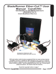
BladeRunner AIO User Manual
CandCNC
With BladeRunner AIO SERVO
Addendums
Release #2 11/17/2012
All Content Copyrighted 2008-2013
any reproduction in printed or electronic formats is prohibited
without the express written permission of CandCNC
CNC and motion control involves equipment that can cause serious injuries.
CandCNC assumes no liability for ANY damages to any person or property
from the proper or improper use of any equipment CandCNC sells or from any
advice verbal or written. Use the equipment at your own risk. Practice good
safety precautions. Be smarter than the machine.
CandCNC
Page
INTRODUCTION: BladeRunner AIO
INTRODUCTION
The BladeRunner AIO is a complete CNC motion controller in a single enclosure that
consists of
1. Advanced logic Interface electronics to connect the signals from a PC and provide bidirectional communication for controlling motion, operator feedback and expanded
Input/ouput (I/O). UBOBIII with Port Expansion for single Parallel Port operation
2. Safety monitoring and auto-shutdown circuits controlled via embedded processors.
Monitors DC (motor) voltage, DC load current and internal temperature. Values
displayed on screen. Less than 1msec total shutdown to out of spec conditions. Fault
shutdown codes on Front Panel and on screen.
3. Exclusive Driver Interface design monitors each axis independently and protects
drives from shorts and overloads. Reports faults with flash code and on-screen in text.
Driver interface card has input high speed opto isolation (step & dir).
4. High quality Gecko stepper drivers with X10 microstepping and tuned anti-resonance
for smooth motion.
5. High capacity toroid linear power supply provides low noise DC power with large surge
capability. AC input has two levels of ON/OFF. AC side fusing (breaker) DC side
Electronic fusing and conventional fusing. Operation on most AC power grids in the
world.
6. Wired and tested motors are specially designed to match Gecko Drivers for optimized
performance
7. Unit is expandable for up to 5 motors and drives (4.5 axis configuration one axis
hardware slaved) for adding double Z motion or rotary axis.
8. Warranty covers labor and parts ( returned to factory) for a full 2 years. All
components including motors and drivers.
IN ADDITION to the Above the BladeRunner AIO DRAGON-CUT offers:
1. Fully integrated Digital Torch Height Control with:
» Dynamic Fault and anti-dive detection
» On-screen display and setting of all Torch Height Parameters
» Full high speed digital response
» Total electrical isolation for safety and noise rejection
» Advanced PWM digital pickup at the plasma via a single cable
» Exclusive HyT-Connect™ SINGLE CABLE plug-n-go interface for all
Hypertherm 45/65/85. Connection kits for most other brands.
» Industry first DCP-01 (digital current probe) option shows actual cut current on
any plasma cutter!
» Instant recall Stored Settings Library. A Cut Profile that is a dynamic Cut chart
stored by material type/thickness.
» More precise control than any other THC (ATHC; AVHC; AVC;THC) on the
market.
2. Same high quality electronics and same 2 year warranty.
CandCNC
Page 2
INTRO
A
INTRODUCTION: BladeRunner AIO
Familiarize yourself with the controls on the BladeRunner Front Panel and with the loading
and operation of MACH3 with the proper profile. The SOFTWARE part of this manual is
devoted to getting MACH3 properly installed with the right CandCNC support files and
profile to run the BladeRunner AIO Plasma and Router. After you have the software
installed and the cables and satellite cards hooked up, you will be guided through a series
of tests to determine if everything is working. We ask that you go through the setup and
manual in the order presented. If at some point you cannot get the expected results and
check your connections and setup with no success, then call our tech support person at
903-364-2740 during normal business hours (posted on the CandCNC website). Often an
email to [email protected] will get a response after hours or on weekends.
Another valuable source of help is the CandCNCSupport Group at
http://groups.yahoo.com/group/CandCNCSupport/
You must have a yahoo membership and you must request to join the CandCNC
forum. The Group is open to all persons interested in CNC cutting and/or
CandCNC products.
Installation and setup of your BladeRunner AIO....OVERVIEW
There are a series of steps you must complete to setup and interface the
BladeRunner AIO with your PC and Your Plasma torch
·
·
·
·
·
·
·
·
·
·
·
·
·
Install and setup the Primary Parallel Port in your PC
Setup and configure the first serial port (COM1) on your PC *
Install MACH3 software (proper version)
Copy your MACH3 license into the MACH3 main folder
Run CandCNC install program from the CandCNC Support disk to load
custom screens and setup files and Plug-ins
Open MACH3 and check screens and configurations.
Connect the 2 PC port cables (one 25Pin, one 9 Pin) to the side of the
BladeRunner *
Run a quick series of tests to confirm the ports are working and that
MACH3 is configured correctly
Tune and Calibrate the motors on each axis.
Setup and Test Inputs and Outputs for Homes and Limits
Check for proper motion
Fire up the machine and cut a test file.
Proceed to the DTHCII setup (Dragon-Cut versions).
* Serial port install and setup is not required for simple Router/Mill operation . Serial
port is used to send and receive information from/to the Expansion Modules (DTHC &
ISS-02). It is also used to display the Power Supply parameters and report faults to
the screen. You can elect not to use a serial port if you are not using the DTHC or ISS02 Modules AND you do not want to see the power supply operational specs (Volts,
CandCNC
Page 3
INTRO
A
The setup of the BladeRunner AIO Series Interface involves the installation of MACH3
software and some support files on the PC to be used for the machine controller.
BladeRunner AIO Table of Contents
BLADERUNNER AIO TABLE of CONTENTS
PART 1, SETUP, CALIBRATION . {CONT)
A. Introduction - Table of Contents
B. BladeRunner AIO Quick Start
1. Basic Connections
a. Parallel Port Cable
b. Serial Port Cable
c. Motor Cables
2. Quik Start list of Quik Steps
2. Slaved Axis Setup
a. 4 motor system
b. 5 motor NOTICE
3. Power Up Motor Check
C. Detailed Install & Setup - PC Hardware
1. PC Requirements & Prep
a. Not Supported List
b. Limitations
c. Profile Copies
d. PC hardware requirements
e. Windows Optimization
f. Unused NIC - Disable
2. PC Hardware: LPT (printer) Port - Motherboard
a Install and Setup Printer Port- Motherboard
b. Using Windows Device Manager to display Ports
c. Check Hex Address
3. PC Hardware : COM (serial) PORT
a. Using Windows Device Manager - COM setup
b. Setup details
4. PC Hardware: LPT (printer) Port - Expansion Card
a. Using Mfg’s disk to setup expansion card
b. Using Windows Device Manager to display Port Address
D, Detailed Install & Setup - Software
1. General Concepts
a. The 3 C’s: CAD- CAM-CONTROL
b. Definitions
c. MACH concepts Profiles and Screen SETS
d. G-Code Definition
2. Installing MACH3 from the Support CD
a. CD file structure
b. Running the INSTALL FILE for MACH
CandCNC
Page 4
A
BladeRunner AIO Table of Contents
TOC
BLADERUNNER AIO TABLE of CONTENTS
PART 1, SETUP, CALIBRATION
D. Detailed Install & Setup - Software (Cont)
3. After the MACH Install
a. Sample Folder Structure
b. Folder Contents Defined
4. MACH3 License Install
5. CandCNC Support Files
a. General Info
b. BladeRunnerAIO-UBOBIII Install Defined
6. Installing CandCNC files from the Support CD
a. CD file structure
b. Running the INSTALL FILE Screen shots
7. Working with MACH3 PROFILES
a. Starting the Profile from the Desktop ICON
b. Starting the Profile from the MACH LOADER
c. CREATE a new PROFILE
E. The BladeRunner ESPII Power Control Unit
1. Making the External Connections
a. PC parallel & Serial Ports
b. Power cables
c. Motor connections
1. Front panel Controls
2. Front Panel Dashboard
F. Configure and Testing BladeRunner with MACH3
1. The MACH3 / CandCNC Screens
a. DTHC Screen Details - Main Screen
b. Diagnostics Screens
2. Getting Motion from the BladeRunner AIO
b. Powering up the system
c. Keyboard Hot keys
3. Using the MACH Configuration interface (Menu)
a. Motor/Axis Calibration and Tuning
1. Table Physics
2. Fine Tuning the calibration
b. Axis Slaving
c. Homing & Limits -preliminary
F(A) ADDENDUM - BladeRunner SERVO system
1. Physical Differences between Stepper & Servo
2. Servo motor and Gearhead Dimensions/specs
3, Setup and Motor Tuning - Servo
4. Gecko G320X default settings
5. Calculations & Formulas
6. Recommended Settings (Typically setup)
CandCNC
A
A
Page 5
G. Detailed Install and Setup - BladeRunner Hardware
1. Table I/O card
a. Card location in the BladeRunner
b. Making the wiring connections
2. The Charge Pump (CP)
3. E-STOP and it’s variants
a. EPO jumper on Table I/O
b. Power on Detection
c. Hardware E-STOP Options
4. Setup and testing INPUTS - HOMES
a. Z axis setup and testing (required for DTHC)
b. Optional XY & A homes
c. Other inputs
5, Setup and Testing INPUTS - LIMITS
6. Setup and Testing OUTPUTS
a. How Outputs work in the BladeRunner
b. Things that trigger an output
b. Testing OUTPUTs
H.. Final system checkout
1. Bringing it all together
a, Final Motion Test
b. Doing an “Air Cut”
CandCNC
A
TOC
BladeRunner AIO Table of Contents
Page 6
BladeRunner AIO QUIK START
BLADERUNNER AIO
QUIK - START
FOR THOSE THAT HAVE PRIOR INSTALL EXPERIENCE OR THAT DON’T
NEED OR WANT DETAILED MANUALS, THE FOLLOWING PAGE WILL GIVE
YOU A QUICK SETUP CHECKLIST.
The pages that follow that are a logical and detailed setup guide. Your chances for
success are greatly enhanced if you follow the detailed manual in the order it is
written.
A PART II Manual is a SERVICE MANUAL with card level details and diagnostic
tools to help you narrow down the possible cause. Most issues are resolved from
either reloading the BladeRunner INSTALL to return all of the settings to default, or
from checking cables and connections.
All Content Copyrighted 2008-2013
The owner of the equipment covered by this manual is authorized to make copies
(electronic or printed) of this manual for their personal use (only), as long as this original
copyright notice is included “Owner” is defined as the person in legal possession of the
equipment . No excerpts or reproductions are authorized for any other use without
written permission from FourHillsDesign/CandCNC. For media reviews please contact
CandCNC for permission to use any photos or text from this manual
CandCNC
Page 7
B
BladeRunner
BladeRunner
AIO
AIO
Table
QUIK
ofSTART
Contents
BLADERUNNER AIO QUIK START
The following is a synopsis of the steps needed to get the BladeRunner installed and setup and moving
the motors:
! Unbox and check the unit to make sure it’s undamaged. If there is any visible
damage from shipping retain the shipping boxes. If possible take digital pictures of the
damage. Contact CandCNC immediately.
! Load the version of MACH3 on the support CD to your PC. Current version we
provide is 3.42.029. If you have already installed a NEWER version then DO NOT
REPLACE IT WITH the version we supply.....You must uninstall the newer version AND
(IMPORTANT!) remove the MACH Pulse Engine from the Device Manager list (Remove
hardware) before you do the install from the CD. We have not fully tested releases of
MACH after 3.42.029
! Load your license file for MACH (see Software section if you don’t know how)
! Use the Support CD and run the BladeRunnerAIO-UBOB3-Install.exe in the AUTO
INSTALL FILES folder on the CD. (some early units had the MP3000E install name)
! Plug in the DB25 cable (supplied) to the PC parallel port and the other end to
PORT1 input on the side of the BladeRunner AIO box
! Plug in the MAIN Power to the BladeRunner AIO box.
! NO MOTORS Plugged in YET!
! Turn on Main Power Switch on end of enclosure. Red LED over OFF switch
should come on and the PWR light on the UBOB panel and the PWR LED on the
FRONT PANEL should light up.
CandCNC
Page 8
B
BladeRunner Basic Connections
BLADERUNNER AIO RIGHT SIDE VIEW
INPUTS FOR UBOB III AND EXPANSION OPTIONS
CLOSE UP VIEW UBOB MODULE
RIGHT SIDE
CandCNC
Page 9
B
BladeRunner Basic Connections
Connecting up the BladeRunner Control box. Take a look at the block
diagram, that gives an overview of the control box. Note that there are two
cables that run from the PC and connect to the BladeRunner box. These are
labeled Port 1, and Serial It's important that you connect the first parallel port in
the computer (normally the existing printer port or LPT1 port) to Port 1 on the
BladeRunner Controller box There are also other cables that connect three
satellite cards (Table I/O, and THC Sensor Module/VFD Interface Card) to the
BladeRunner-DTHCII or Spindle Speed as well. The Table I/O is connected
Internally and is not part of the connections to the PC.
1. Install a DB25 Male to Female extension cable (All pins straight through)
between parallel port (PORT1 on the PC to the part marked Port 1 INPUT
(Orange highlight below) on the front of the MP3000-DTHC controller unit.
2. Install a straight through DB9 Male to Female cable (not a null modem
cable) from your Com1 port on the PC to the Serial port on the
BladeRunner
PC Parallel Port 1
Serial Port
PC
CandCNC
Page 10
B
BladeRunner Basic Connections
A
Z
A1 A2 B1 B2
A1 A2 B1 B2
Y
A1 A2 B1 B2
X
A1 A2 B1 B2
HW SLAVE
A1 A2 B1 B2
IMPORTANT:
Screw Terminals
Face UP
1
!
It is important that the stepper motor wires are wired correctly. When
shipped from the factory the motors are wired right and each one is
tested with the unit. Because motors for other products we sell are
wired differently it’s possible a motor you order after the unit has
been shipped could be wired differently. DO NOT ASSUME THAT
THE COLOR OF THE WIRES IS CONSISTENT. We order wire from
different sources and cannot always define the wire colors. If you
take the connectors off for any reason either mark the wires by
position or use an ohmmeter to test for coil pairs (see Bladerunner
Manual PartII Service Manual). If you use any other motor or rewire
for any reason CHECK TO MAKE SURE THE COILS ARE
COLOR CODE MAY VARY
MOTOR SIDE
BladeRunner ESPII box
(See Section F Addendum for views of
BladeRunner Servo Systems)
CandCNC
Page 11
B
! Push the ON (White Button) RUN LED (green) should light. You should hear a
faint click inside the unit. Main fan (end of enclosure) should turn on. (on later
models the fan may come on as soon as the Main Power switch is activated.
! If for any reason the unit fails to power up, unplug it from the AC and open the
front cover (4 screws) and carefully set the front cover aside and check all of the
cables and wires to make sure none have come loose in shipping. Refer to the
manual detail pages to confirm cable connections.
! Once you have the power-on sequence operational: TURN THE DC OFF
USING THE RED OFF BUTTON ON THE FRONT PANEL. RED LED SHOULD BE
ON.
! Plug a motor into the X motor connector on the side of the BladeRunner AIO
case. (requires match encoder connection for servo motor systems)
! Turn on the Motor DC Power using the FRONT Panel ON Button. Motor will
lockup after about a 1 sec delay. Lock up is defined as the motor becomes difficult or
impossible to turn.
! Turn off Motor (DC) Power (you can leave the Main power Switch on)
! Plug in the other motors and make sure they lock up when you turn on the Motor
DC using the front pushbutton.
! Start MACH and select the BladeRunner_Router OR BladeRunner Plasma Icon
!
With motor power ON and MACH running the profile. hit the RESET button.
If you cannot bring MACH out of reset:
1. Open MACH3 Diagnostics Tab. If “External E-stop Request “ error is flashing
then the EPO Jumper on the table I/O is not in place OR the Table I/O card is not
connected.
2. E-Stop input is OPEN or E-Stop polarity is wrong. Open
CONFIG/Ports&Pins/Input Signals and make sure E-STOP input Active Low is set to
RED X
If you CAN come out of reset:
The Charge Pump LED on the UBOB Panel should come on.
IF it does not
1. You may not have communications to the parallel port on your PC.
2. The EPO jumper may not be in place on the Table I/O card inside. If you
still cannot get MACH out of RESET then go to the UBOB section in this manual and
check the cables. MAKE SURE YOU ARE RUNNING THE RIGHT PROFILE IN
MACH.
CandCNC
Page12
B
QUIK START
BladeRunner
BladeRunner
AIO
AIO
Table
QUIK
ofSTART
Contents
BladeRunner
BladeRunner
AIO
AIO
Table
QUIK
ofSTART
Contents
Once you have the power lights and CP light on and out of RESET you are ready
to do a preliminary motion test.
!
NOTE: IF YOU HAVE A 4 MOTOR SYSTEM, the A axis should be software slaved
to the axis you have designed as the Gantry motion axis (X or Y). We do not have
that setting as a default because we do not know which axis you will designate as
the gantry motion axis.
To slave the axis in software: Open MACH3 CONFIG/AXIS SLAVING
Select the Axis you wish to slave the A to (X or Y and click the A radio button on that
IMPORTANT NOTE: IF you have the 5 axis 620-5 system (shipped with 5 motors.)
The slaving is done differently. When setup at the factory the 5th axis is
HARDWARE slaved to Y. If you are setting up a 5 axis system EVEN IF YOU DO
NOT INTEND TO USE THE 4th independent axis at this time you should use the
5th axis as the slave axis and disregard the SOFTWARE SLAVE above
END OF QUIK START
Proceed to Advanced Setup
CandCNC
Page13
B
PC Requirements & Preparation
A NOTE ABOUT RUNNING A PC WITH MACH3
There is a tendency to treat the PC used for the CNC machine as a general purpose workstation
and use it for other purposes when it is not cutting. We strongly urge you to resist the tempation to
use the PC on the CNC table for ANY other purpose than as a DEDICATED CONTROLLER
running MACH3. With the requirements of the PC being modest, an older or refurbished PC
makes a nice machine to dedicate to the task. You will NOT get better performance from a new
super-duper, quad processor PC with 8G of RAM and a 500G HD! Optimize and treat the PC with
MACH as a CNC controller and you will have fewer issues and a better use of your equipment.
Use you hot new PC/Laptop to Draw and do the CAM work. Take it to the Controller PC and us it to
cut the job
THE FOLLOWING CONFIGURATIONS ARE NOT SUPPORTED:
?Any Windows 64 bit install
?Any non-parallel port pulse card or control (e.g. Smooth Stepper, USB drivers, etc)
?Laptops (even with a parallel port)
In addition: While WIN7 is supported by MACH we do not currently support WIN7 running the
BladeRunner. The problem with WIN 7 is usually the drivers for the hardware on the PC and
not something we can help troubleshoot. In other words: You can try to use WIN 7 and it
MAY work but if it does not, please don’t call us for support.
Other Limitations:
We have included a version of MACH3 on the Support CD that has been tested and certified
to work with our plug-ins and screens. If you have already installed a LATER version then it
MAY work. If you experience problems with a version newer than our version on the CD then:
[SEE THE “BEFORE YOU UNINSTALL MACH.....” BELOW]
1. Uninstall the newer version of MACH using Windows Software Install/remove program
2. Open the Hardware Manager on the PC and uninstall the MACH PULSING ENGINE
device in the hardware list.
3. Do a fresh install of MACH3 and re-install the CandCNC files (INSTALL) off the CD
BEFORE YOU UNINSTALL MACH OR DO A REINSTALL OF THE CandCNC INSTALL OFF
OF THE CD
If you have settings you would like to preserve from the earlier install make a copy of the
MACH3 folder on your drive using another name or roll it over to a memory stick. The
important files will be the specific PROFILES (all have XML extensions on the file name). You
can copy the older XML profile over to the new install BUT if there is a bad setting it will
transfer that too. One way around this it to open MACH Loader and CREATE a new Profile
with a New Name and CLONE it from the profile you are using .You can then copy the Cloned
profile back to the install from your COPY of the MACH folder and run it in place of the default
profiles created during and install. Even if it does not work right you can move the motor
tuning and other setup values from the cloned profile.
CandCNC
Page 14
C
PC Requirements & Preparation
C
TO run MACH3 with the Bladerunner and Bladerunner Dragon-Cut™ Systems:
1. Pentium 4 PC
2.4 to 3.4 GHz Processor
512M to 1G RAM
20G Harddrive
1280 X 1024 SVGA (no shared system RAM)
1ea 25 pin LPT (Parallel) Port
1ea 9 pin SERIAL(COM) Port
Windows XP SP2 or SP3
Keyboard
Mouse
2. Optimized Windows setup
No automatic updates running
Disable Remote Assistance
No Virus Checker or background file checkers
No unconnected Ethernet cards (disable if not connected to a cable/hub)
Turn off all non-essential background processes in Windows
3. Disable Startup Items in Registry
1. Click Start button.
2. Click Run.
3. Type MSCONFIG and press [ENTER].
4. Click Startup tab.
5. Uncheck everything
6. Click OK.
7. Exit MSCONFIG.
4. Disable Indexing on all NTFS drives
1. Double click My Computer.
2. Right click on hard drive and choose Properties.
3. On bottom, uncheck "Allow Indexing Service to index this file for
faster searching".
4. Hit OK.
5. Disable Power Management
1. Right-click on your desktop, and then click Properties.
2. Click on the Screen Saver tab.
3. Set Screensaver to None.
4. Press the Power button near the bottom.
5. Set all options to NEVER shut down automatically!
6 Disable Wallpaper
1. Right-click on your desktop, and then click Properties.
2. Click on the Desktop tab.
3. Where it says Background, scroll all the way up and choose None.
4. Click OK.
CandCNC
Page 15
7. Disable any unused network cards.
1. Open Control Panel/System/Hardware/Device Manager
2. Scroll list to Network Adapters
3. Click to show list of adapters
4. Right click unused Network Adapter
5. Select DISABLE.
6. Select Yes
Note: The PC can be used in the network or with a wireless card but it is important that if the
network is not available (card is not connected to a cable and hub) that it be disabled.
Ethernet communications will interrupt MACH (and the pulse stream). An unconnected card
will continually search for a hub every few seconds even if it has no traffic for the network.
When connected to a valid network it no longer will “beacon”. Do not transfer files or use
any Windows utilities when you are running code!
CandCNC
C
PC HARDWARE
PC Requirements & Preparation
Page 16
INSTALL and SETUP PRINTER PORT (LPT)
Motherboard Port
In WINDOWS:
1. Go to START (lower left) CONTROL PANEL
and select SYSTEM from the list You will see a
screen simialr to the one on the left
2. Select HARDWARE Tab.
3. You will see a window like the one below.
4. Select DEVICE MANAGER
5. A list of all the hardware devices on your PC
will appear.
see next page to continue
CandCNC
Page 17
C
INSTALL and SETUP PRINTER PORT (LPT)
Motherboard Port
In WINDOWS:
6. Scroll down the list until you find the PORTS (Com & LPT)
line
7. Expand the line (+ button).
8. Find the PRINTER PORT (LPT1) and click the line to open
the TABS.
9. Click the RESOURCES Tab. You should see the screen
below and the I/O Range should start at 0378.
If you do not see that LPT port in the list or you have another
address for LPT1 under the RESOURCES proceed to the
next section
If you have the screen shown you have a Motherboard
Parallel Port at the default address and your Bladerunner
default install will use that address. You can move to the
COM port setup page.
CandCNC
Page 18
C
NOTE: USE THIS SECTION ONLY IF YOUR PC DOES NOT HAVE A BUILT-IN
PARALLEL PORT and/or SERIAL PORT
Use the same procedure to install a primary (PORT1) Parallel Port (if your PC does
not have one) or a secondary port (PORT2). Do not attempt to use two separate
parallel port cards of the same type to get two ports. For two ports use a Dual
Parallel Port card.
Make sure the card you install has drivers for the version of Windows you are running.
Win2000 drivers may or may not work in XP (or visa versa). When you install the card in
your computer and turn it back on, it should find the new hardware and when prompted,
you should use the disk that comes with the port card to install the correct drivers. There
should be instructions with the card on the proper way to install the drivers.
After you install the parallel port and Windows recognizes the port(s) then open the device
manager from the Hardware section under Windows /Control Panel/System and open the
Ports icon and find the Port entries. Open that and click on the resources tab.
WRITE PORT
ADDRESS HERE
Write down the first number in the Input/Output range (DE00 in this case above). We will have to enter
that number in the MACH3 setup procedure later
CandCNC
Page 19
C
PC HARDWARE
INSTALL and SETUP PRINTER PORT (LPT)
Expansion Card Port
C
PC HARDWARE
PC hardware - COM Port
You will have to setup the COM1 serial port in Windows. It should be setup with 9600 baud, 8
bits, no parity, 1 stop bit, no Flow control
Testing: We will test the functionality of the com port after we hook up the BladeRunner
to the computer
CandCNC
Page 20
SOFTWARE INSTALL
SETUP
BLADERUNNER AIO SUPPORT CD.
!
Contains Auto Install File to automatically load Drivers (Plug-ins), Custom Screens,
and Custom Profiles for router and plasma.
!Contains
Complete Manual and all associated Manuals for internal cards.
!Contains
tested version of MACH3 software (DEMO VERSION).
!Contains
sample artwork for plasma and router.
!Contains
Demo version of DXFTools for smooth arcs and curves from CorelDraw DXF
export.
!Contains
Demo version of SheetCAM.
!Contains
Demo version of nesting tool for SheetCAM.
!Contains
Basic TubeSlicer ™ Plug-in.
CandCNC
Page 21
SOFTWARE
INSTALL
D
GENERAL CONCEPTS
READ THESE NOTES!
It helps to have a basic understanding of how MACH operates, what it does and how it combines with
the BladeRunner Hardware to generate motion.
! There are 3 distinct parts (legs) of CNC: CAD(Drawing), CAM (Toolpathing) and CONTROL
(operation of the hardware and operator interface. MACH is the third and last (CONTROL). It does
not generate toolpaths from a file; it cannot be used to draw or edit artwork. It runs a specific “dialect” of
G-Code.
! Specific software programs are used for the CAD(drawing) to generate the base artwork in vector
format. For simple shapes a pure CAD program can be used. For artistic, decorative or signage type
cuts, a drawing program that allows drawing in vector format (lines) will better fit the needs and is a lot
faster than pure CAD. It will allow import of several Vector type formats to allow you to use vector clipart
(like the files found at www.VectorArt.com) The two most popular drawing programs are CorelDraw (any
version after 11) and Adobe Illustrator. A FREE alternative is Inkscape and is included on our Software
CD. You can download it from http://inkscape.org/download/?lang=en
! The CAM process takes a drawing file and allows the user to import it in line format, define the
objects to cut and in what order, with which tool and what type of cut. Better CAM programs have
automatic lead-ins/outs (essential for plasma) and cut type settings. The most essential piece is the
“POST” processor that translates the CAM program’s native toolpath data to standard G-Code in a form
that matches your control program (MACH3). The best value and most flexible CAM for 2 D or 2.5D
cutting is SheetCAM. It is available at www.SheetCAM.com. SheetCAM TNG is a part of our Software
Bundles
! Some programs combine CAD and CAM or CAM and CONTROL but they typically are a
compromise and one or more section will not be as robust as the other. To maintain maximum flexibility,
and not be placed in a position where you have to change out an expensive tool (or quit using a section),
it is recommended you run separate applications for each “leg” of the CNC Triad. You can then pick and
choose the features from each one that best suit the type cutting you do.
! MACH uses setup “Profiles” stored in the main MACH3 Folder as an XML file. It stores all of the
settings about the hardware and interface (input pins, output signals and pins) motor tuning and travel
directions. We use a term called “mapping”. It refers to defining a specific function to a specific port and
pin setting in MACH. The BladeRunner Install copies the “profiles” needed to the MACH folder to run the
Bladerunner Hardware. Certain settings that are specific to you machine (motor tuning, travel
directions.etc) have to be entered during setup. The settings get stored in the current running PROFILE.
screen presentation for the BladeRunner is in the form of a custom screen “set”. The file is
stored in the MACH3 Folder and has a .set extension. It controls what buttons, readouts (DRO’s) and
bitmaps (pictures) are on the screen. The visual look is controlled using custom bitmaps. Bitmaps used
with CandCNC screens are all stored in a folder located in the Bitmaps Folder (under MACH3) and in a
sub-folder named CandCNC. With the exception of certain custom objects in a screen there is no setup
information. Certain operations on the Bladerunner (parameter feedback and DTHC or Spindle Speed
functions) MUST use the associated screen set to operate properly.
!The
G-code runs in MACH and gives it moves in absolute (measured from a beginning zero point) XY
and Z coordinates. It’s up to MACH to process the file, do the math and based on the settings in the
Profile, issue the proper number of pulses (steps) and proper direction (dir) to the motor drive modules
(hardware). There is no positional feedback between MACH (software) and the table position
(Hardware). MACH is not “closed loop”. It issues the signals at the rate set by the motor tuning rules
and it’s up to the hardware to move to that location.
!The
CandCNC
Page 22
SOFTWARE
INSTALL
D
SOFTWARE INSTALL
OVERVIEW
SOFTWARE
INSTALL
D
Installing MACH3 and the custom BladeRunner files
The actual installation of MACH3 software is straight forward since the file is downloaded
from CandCNC support CD and the file when clicked on will take you through an install of
the software on your machine. We have included an unlicensed version (demo) of MACH 3
that is needed to use with the BladeRunner series of devices DO NOT TRY TO USE AN
OLDER (EARLIER) VERSION THAN WHAT IS INCLUDED ON THE SUPPORT CD
While we can answer questions about the proper interface of our BladeRunner with
MACH3, the actual setup and use of MACH3 on a specific PC may better be handled
through the actual software provider or the support list. Our custom files provided on our
install disk should setup the PC to work correctly with the BladeRunner, but be aware that
changes you make to setup parameters after the install make changes to the profile. Make
a copy of the BladeRunner XML files in the MACH folder (backups) when you have
finished setting up the unit. It will save you a lot of time and frustration if you ever
need to recover from PC hardware problems. Any time you make setup changes to a
profile then refresh the backup. Store it and your MACH license file on an external device.
We have included a version of the MACH3 Manual on the CD. For plasma cutting most of
the manual information is not needed and if there is a conflict between a plasma specific
setup or procedures, (this) Bladerunner manual should prevail.
The following pages will take you through the install and setup of you CONTROL PC. First
you will install MACH3 then run the BladeRunner Auto installer to do a custom setup on
MACH for the BladeRunner and the DTHCII. Detailed setup and testing of the DTHCII is a
separate manual on the CD titled DTHCII Manual.
NOTE: THE MP3000 products use the same electronics and interface as the BladeRunner
CandCNC
Page 23
INSTALLING MACH3
INSTALLING MACH3 FROM THE SUPPORT CD TO YOUR CONTROL PC
1. Locate the Support CD (same one this manual is on) and open the Main Folder
(Root) of the CD drive. Use Windows File Explorer or My Computer and navigate to the
CD Drive onthe PC
2. Open the CD and the folling structure should be displayed:
3. Navigate to the MACH Program Folder
4. Double Click the Mach3Version3./042.029.exe line. The sutomated install of MACH
will start
CandCNC
Page 24
SOFTWARE
INSTALL
D
INSTALLING MACH3
SOFTWARE
INSTALL
D
MACH will ask you for
the default installaion
Disk and folder to use.
SELECT THE
STUCTURE IT SHOWS.
DO NOT CHANGE IT
OR OTHER INSTALLA
MAY NOT WORK
CORRECTLY
Several Features will be
selected by default
(checked) Turn off
Wizards, LazyCam You
can turn off Screen sets
unless you want to use
the Default MACH
screesn to build your
own screens
(experienced MACH
users ONLY)
Make sure you leave
Parallel Port Driver
checked . Hit the NEXT
button
CandCNC
Page 25
INSTALLING MACH3
SOFTWARE
INSTALL
D
Do not create any
profiles in this
screen. All of the
Profiles you will
need for the
BladeRunner
System will be
automatically
created in the next
section of the
software install
section
THIS IS AN
IMPORTANT
SCREEN. It indicates
that MACH is adding in
the Parallel Port Driver.
This is a Hardware
Driver installed into the
Windows Hardware list
and is used to
generate the high
speed outputs and
inputs needed for
proper operation of the
BladeRunner and the
CandCNC
Page 26
MACH3 SOFTWARE
Basic Structure
SOFTWARE
INSTALL
D
MACH FILE STRUCTURE
SAMPLE FOLDER STRUCTURE:
Some folders are added for
specific options so your folder view
will not have all of the ones shown
on an initial install. The important
ones are listed below
This is located on the C:/ drive of
your Control PC.
FOLDER
From time to time if you add
features or certain upgrades are
installed there can be added
folders and/or changes to files. We
make available specific files that
upgrade files in this structure. In
some cases the user must open
the specific folder and copy the
new file into (or overwrite an
existing file) in a folder. Being
familiar with the structure makes
this process easier
CandCNC
CONTAINS
Bitmaps
Contains Bitmaps (custom backgrounds
and Buttons) for the custom screens.
CandCNC has a Folder under Bitmaps
for the specific bitmaps for our screens
GCode
Sample G-code for ROUTER. Do not
use except for testing motion it will not
work with plasma
Macros
Contains Sub-folders of macros for
EACH generated Profile. In the specific
sub-folder that are macro files. When
you call a macro by number from
code or internally it uses the specific
macro in the folder of the same name
as your running profile.
Plugins
A folder of plugins installed. The base
plugins for CandCNC are the ccc_comm
and the ccc_ubob. Others are installed
with options like the PN200. Every
plugin the folder will be “seen” by MACH.
The Configuration of a plugin
including enabled and disabled is
stored in the specific XML (profile) so
they can be differnt configurations in
different profiles
xmlBackups
Backup copies of the Profiles XML’s for
your system. Can be renamed and
copied back to the MACH main folder to
bring back a damaged XML. You should
STILL perform file backups onto another
media source of your XML files anytime
you change settings.
Page 27
MACH2 LICENSE INSTALL
INSTALLING THE MACH 3 LICENSE
1. Locate your Software Support CD. It is a separate CD from the Support
CD. If you purchased either of the CandCNC Software bundles you should
have the Software Support CD
A NOTE ABOUT THE
MACH3 LICENSE FILE:
The Mach1Lic.Dat is an Encrypted
file. You CANNOT open it. It
must be copied intact using the
steps below. Each License file
has a unique serial number issued
to CandCNC. We keep a
database of all licenses and in the
event you misplace your license
contact us and we can issue a
replacement.
2. Open the Software Support Cd to the top folder (root) and click on the README
FIRST .txt file. It will open in NOTEPAD. It will explain the licenses and the way
CandCNC can issue licenses.
If you already have a MACH license or have bought from another source the
procedure is the same but the location of the license file will be different
3. Select the Licenses Folder and then the MACH folder under that
If you have purchased a MACH3 license or Software bundle from CandCNC then In
that folder you will find a single file.
To license MACH3.
1. Use File Explorer and RIGHT CLICK on the Mach1lic.dat file and select COPY
(this copies it to the Windows clipboard)..
2. Immediately Use File Explorer to navigate to the C:/MACH3 folder on your
system Hard drive (C:). Right click the MACH3 folder in File Explorer and select
PASTE from the menu. That will copy the file in the MACH3 main folder on your
control PC.
3. Open the MACH3 folder and display a list of the files in the righthand portion of
the Screen. Make sure the Mach1Lic.Dat was copied.
NOTE: MACH will load and run in DEMO mode without a license. It is fully
functional with the exception it will only run about 500 lines of code and advanced
features like the THC logic are not functional. You MUST have a valid license
loaded before you can use the DTHCII in MACH
CandCNC
Page 28
SOFTWARE
INSTALL
D
CandCNC SUPPORT FILES
Install
THE FOLLOWING PAGES COVER THE INSTALL OF THE BLADERUNNER
CONFIGURATION FILES FROM A MASTER INSTALL (EXE) FILE
The Auto Installer Files will automatically load all of the CandCNC support files for MACH3.
You must have MACH 3 (version 3.42.029) off this CD installed and running first THEN run
the appropriate installer. Most installs will use the BladeRunnerAIO-UBOBIII_Install file.
YOU DO SHOULD NOT RUN THE MP3000E-UBOBIII_install unless you contact us and we
tell you to run it.
The installers will load both the Router and Plasma profiles and both ICONs will show up on
your Desktop. Each profile for MACH (XML) stands alone so if you want to use both you
must setup both profiles with the Motor Tuning and any other parameters that are exclusive
to your machine
For reference the full MACH3 Manual is in the Manuals Folder. You will also find the
BladeRunner AIO Manual there as well. We also post the latest manuals on our website
http://www.CandCNC/com/Manuals.htm. Expansion Cards (DTHC II & ISS-02) have their
own manuals for install, setup and use.
If you have purchased the BladeRunner AIO Dragon Cut for plasma cutting you will also
need to refer to the DTHCII _Setup-Config or DTHCII-setup_install-full.pdf
All Manuals are in PDF format. You will need to have the Adobe PDF Reader installed
(Free) to view or print the manuals.
IF YOU DO NOT HAVE THE SUPPORT CD or it is more than 90 days since you received
your BladeRunner you should check http://www.CandCNC.com/Manuals.htm for the
BladeRunner Installer (ZIP) at the bottom of the page. You can download, unzip and run
that installer
STRUCTURE OF THE SUPPORT CD.
CandCNC
Page 29
SOFTWARE
INSTALL
D
CandCNC SUPPORT FILES
Install
BladeRunnerAIO-UBOBIII Install: What it DOES:
1. Copies two PROFILES (XML’s) to the MAIN MACH Folder
2. Copies several Screen SET files to the MAIN MACH Folder
3. Creates a folder under MACH3/Bitmaps named CandCNC
4. Copies all of the bitmaps for the MACH screens to that folder
5. Copies the custom drivers (PLUGINS) to the MACH3/Plug-in folder
6. Opens the MACH3/macros folder and creates a folder for each Mach Profile
added in step 1
7. Removes default MACH profile links (Icons) from the Desktop
8. Puts two custom Icons on the Desktop for the BladeRunner Plasma and Router
WHAT IT DOES NOT DO:
Load or install MACH3
Load or install any other software
Setup the MACH3 Profile for your specific table/machine
TO START THE INSTALL FROM THE CD OPEN THE CD TO THE STRUCTURE
in the ROOT folder of the drive and double click the BladeRunnerAIO-UBOBIII.exe
file. The install will start with a series of windows. In most you will just hit NEXT.
CandCNC
CandCNC
Page
Page 30
SOFTWARE
INSTALL
D
CandCNC SUPPORT FILES
Install
Basic information
about the
CandCNC
software and
programs. Take
a couple of
minutes to read
the text (as
boring as it is) so
you will know the
details about
your CandCNC
products. We
have made the
custom drivers
and our software
as non-restrictive
as possible. It
does not limit the
resale or use by
a legal owner.
If you installed
your MACH3 in
the C:/ drive on
your Control PC
as we suggest in
the MACH Install,
Then just hit the
NEXT button on
this screen.
CandCNC
Page 31
SOFTWARE
INSTALL
D
CandCNC SUPPORT FILES
Install
SOFTWARE
INSTALL
D
Another screen of
information we think you
should know so humor
me and please read it !
FINISHED!!
Once you have installed the BladeRunner Install file then you can start the final
setup, calibration and basic motion tests of your BladeRunner. You can always get
back to the basic default values for a BladeRunner if you simply rerun the install
again, BUT BE AWARE that any configuration changes (including motor tuning
etc) will go back to the install defaults. The following page will cover how you can
start the specific PROFILE (BladeRunner DTHC or the BladeRunner Router) and
how you can create your own PROFILES.
CandCNC
Page 32
Starting The MACH PROFILE
SOFTWARE
INSTALL
STARTING THE BLADERUNNER PROFILE
From the the Desktop on the computer
Look for the C3 Icon and select the Plasma or
Router Profile to run. If the C3 icons are not
present you may find it installed them with a
generic icon like this
it will run from either Icon
HOW TO RUN FROM THE MACH LOADER:
The MACH LOADER ICON should still be on the desktop. It gives you
access to a MENU of installed profiles that exist on your setup.
Your display may have
more or less profiles that
the screen here. You need
to see at least the
BladeRunnerAIO-DTHCUBOB3 and the
BladeRINNERAIO-ROuterUBOB3 in the list.
Thereare several hings you can do at this point.
1, You can highlight and delete unused profiles.
2. You can highlight and RUN a specific profile by clicking OK after you
highlight the file name in the list.
3, You can Create a NEW profile (see next page)
CandCNC
D
Page 33
Wroking with
MACH PROFILES
TO CREATE A NEW
PROFILE:
1. Select Create from the
previous screen you will get
a window similar to the one
on the left.
2. Type a new name in the
input box under New Profile
Name. Leave the Default
Profile Values Box
UNCHECKED
3. Find a Profile in the
Clone From List you want
to copy all of the settings
from.
4. Highlight the File you
want to Clone From.
5. Click OK
6. The new PROFILE will
appear in the selection list.
It will have all of the settings
of the PROFILE it was
Cloned from. It also sets up
a folder under the MACROS
folder with all of the same
macros the original had.
To make new profiles or to change the Profile Name DO NOT simply rename the
PROFILE (XML) in the MACH folder. It will show up the list as a new name but
there will be no corresponding MACROs folder so you may encounter problems
trying the run form that profile
.
IF YOUR RESTORE A PROFILE FROM A BACKUP or ANOTHER SOURCE of
the same name it will overwrite the exiting PROFILE and chagne all of the settings
to those of the backup.
NOTE: While a profile of another name contains all of the settings you may need
to run MACH it lacks the matching Macro Folder created during a Clone. You
should first create a Clone of an existing profile using the same name as the file
you wish to transfer in and THEN overwrite it with the imported file.
CandCNC
Page 34
SOFTWARE
INSTALL
D