1
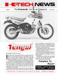
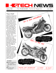
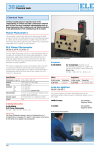
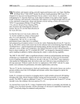
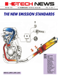
Fall 1993
The Kawasaki
Technical Magazine
Vol. 6 No. 3
by Patrick Kelly
Instructional Designer/
Instructor
First the Z-l. Then the
900 Ninja®. Both became
legends in their own time,
setting standards for motorcycles for years to
come and putting an indelible stamp on the history
of motorcycling.
Now, there promises
to be another legendary
Kawasaki 900—the ZX-9R.
The ZX-9R, officially
designated the ZX900-B1,
is based on the ZX750L/M. It is engineered to offer the latest in handling,
braking and suspension
while at the same time providing a high level of comfort, fit and finish.
The ZX-9R’s powerful
engine is basically a bored
and stroked version of the
ZX-7 engine. The bore
goes from 71mm up to
73mm and the stroke
goes from 47.3mm to
53.7mm giving a displacement of 899cc.
To handle the increased displacement and
torque, the main bearings
and rod bearings are increased in diameter by
1mm. The cases are also
redesigned to clear the increased stroke and the
crankcase bolts are increased in diameter 1mm
to increase the clamping
force of the crankcase by
32 percent.
Because of the ZX9R’s larger bore, a closed
deck cylinder with wet liners is used instead of the
CONTlNUED ON PAGE 2
ROUTE LIST.- o
P L E A S E
SERVICE
R E T U R NT O
o PARTS
S E R V I C E
o
L I B R A R Y
SALES
Inside!
n Service tips & more!
Power ...
CONTlNUED FROM PAGE 1
ZX-7’s open deck cylinder
with dry liners.
The ZX-9R’s engine
retains the same compression ratio as the ZX-7’s
(11.5:1) and also utilizes
the same intake valves,
exhaust valves and intake
and exhaust camshafts.
Although the transmission gear ratios remain unchanged from the
ZX750-L, the primary gear
ratio is changed from
1.754:1 to 1534:1. The
clutch is also revised
slightly to handle the ZX9R’s massive torque. The
driving plate friction material is now paper-based instead of cork-based to
help resist deformation
from heat. Stronger clutch
springs are also used to increase the torque capacity.
To reduce noise generated from the engine, a
silent cam chain is used instead of the ZX-7’s roller
chain, and a rubber
damper is added to the
outside of the right side of
the cylinder.
Twin ram air ducts below the headlight feed fresh air over the frame rails to the airbox. (BELOW) ZX-9R’s unique exhaust crossoverpipe for improved torque output.
2 K-Tech News
l
Twin ram air ducts located below the headlight
feed fresh cool air back
around the inside of the
‘airing and over the frame
rails to the airbox underneath the fuel tank. The
air flows through a large
air cleaner element (15
percent larger than the ZX7’s) to Keihin CVKD
40mm carburetors (up
from the ZX-7’s 38mm
carbs). A resonance box is
connected to each ram air
duct to lower intake noise.
The ZX900-B uses a
digital ignition system
which limits rpm to
11,700. This new ignition
system fires unique double-electrode spark plugs
which improve combustion efficiency at low and
middle engine speeds.
Exhaust gasses exit
this new engine package
through an exhaust system based on the ZX-7’s.
Unique to this system is a
crossover pipe which connects all cylinders together for improved Iowand mid-range torque,
and rubber mounting not
only at the silencer but underneath the engine as
well for reduced vibration
and increased durability.
The ZX-9R’s main
frame is similar in construction to the ZX-7’s,
using pressed aluminum
sheets welded together
and then joined to cast
sections at the steering
stem and swingarm pivot.
This frame construction allows the frame to have
maximum strength and rigidity with the least weight
possible. The main differences from the ZX-7’s
frame are a larger cast
piece at the swingarm
pivot and two aluminum
downtubes underneath
the engine. The two removable downtubes are a
necessity since the ZX9R’s engine is rubbermounted in front for less
vibration.
The ZX-9R’s suspension is a recalibrated version of the ZX-7R’s fully
adjustable suspension. Up
front are 41 mm inverted
forks with 12-way rebound
damping adjustment,
seven-way compression
damping adjustment, and
threaded spring preload
adjusters. The fork springs
are buffed on the outside
to eliminate “break in” and
the fork bushings are
chamfered to eliminate
stiction.
In the rear, a nitrogencharged gas shock with a
remote reservoir is used.
This shock has 20-way
compression damping adjustment as well as fourway rebound damping
adjustment. Spring preload is adjusted with a
threaded collar and ride
height is adjusted by a
threaded upper shock
mount. The Uni-Trak linkage characteristics are
identical to the ZX-7R’s,
and the swingarm, with
the exception of longer
chain adjusters, is identical too.
Braking chores up
front are handled by dual
320mm discs gripped by
four-piston calipers. The
calipers use two pistons of
the same bore on each
side of the disc.
In the rear, a single
piston caliper is used
along with a 230mm disc.
A unique feature of the
rear brake system is that
the caliper bolts directly to
the swingarm and no
torque rod is used.
The ZX-9R rides on
the same, wide 17-inch
rims as the ZX-7. Tires are
ZR rated radials, 120/7017 at the front and 180/5517 at the rear.
Although the ZX-9R
offers “racer replica” performance, it does not do
so at the expense of refinement and rider comfort. The handlebar
position, footpeg location,
and seat are all designed
with both function and
comfort in mind. The fairing is larger than the ZX7’s, providing improved
protection from wind and
rain. The inner portion of
the cowling is painted for
a sophisticated look.
Clutch and brake levers
are four-way adjustable
for rider preference. There
is a handy storage space
for a lock under the seat.
Instrumentation in-
cludes a fuel gauge along
with a speedometer, tachometer, dual tripmeters
and a water temperature
gauge.
Welcome the ZX-9R
to the Kawasaki Ninja family. The power and precision of the new ZX-9R
promise to set new standards for motorcycles to
come, and stir the passion
of motorcycling for another generation. o
A new radiator increases the cooling capacity over the ZX-7 by 11.5 percent.
(BELOW) To save weight, the rear brake caliper is bolted directly to the swingarm.
The Technical Magazine 3
l
Fall 1993
Vol. 6 No. 3
©1993 Kawasaki Motors
Corp., U.S.A. (KMC).
All rights reserved.
K-Tech News Staff
Publisher
Kawasaki Tech Services
Publications Manager
Don Church
Executive Editor
Gary Herzog
Editor-in-Chief
Gregg Thompson
Communications Editor
Patrick Kelly
Regional Editors
North and East
Fred DeHart
Central and South
Walter Rainwater
Contributors
David Corey, Randy Davis
Keith Pestotnik, David Pyle,
Ray St. John
Graphics/Production
Graphic Art
Gregg Thompson
Copy Editor
Pat Shibata
Production
Nickless Communications
Published by Kawasaki.
All suggestions become
the property of KMC.
Sending a service suggestion gives Kawasaki permission to publish and/or
use it without further consideration.
Specifications subject to
change without notice.
4 K-Tech News
l
Technical training survey results are in
by Ray St. John
Question 2: We asked
Supervisor, Technical Writing
During the last week in
July this year, the Service
Training and Communications Department at Kawasaki mailed out a survey
form. Its aim? To find out
what you want from this
winter’s technical training
season, and what you
thought of the recently
completed Service Contest.
Here is a summary of
the results:
you which training subjects you wanted most
and you said electrical
troubleshooting. (We hear
you!) Next we had a fourway tie between motorcycle fuel systems, periodic
maintenance procedures
(how to change spark
plugs, clean air filters, adjust chains, set valve lash,
and so on), JET SKI watercraft service, and motorcycle engines (ZXs, V-twins,
and all the rest).
Question 1: The video-
Question 3: Apparently,
tape everybody most
wants to see is on engine
diagnostics, including twostroke pressure and vacuum testing, finding oil
leaks, oil pressure and
compression testing, and
carburetor vs. ignition
problems. Next in popularity is a tape on power
trains, with segments on
motorcycle transmissions
and final drives, and ATV
automatic clutches, reverse, and dual-mode and
limited slip differentials. A
lot of you voted for a tape
on the 750 JET SKI® watercraft covering engine
disassembly and assembly, carburetion and other
new features. A fair
amount of interest was
also expressed in MULE™
2500 series service.
no one has a problem with
the shorter technical training season.
Questions 4-7: It looks
like you want the Service
Contest to have fewer
questions per segment
and you want it presented
in the winter when you
have the time to work on
it. Watch for some revisions here.
Question 8: There were
very few additional comments, but one stood out:
“Thanks for listening.” We
have one thing to say in return: “Thanks for letting us
know what you want from
the Service Training and
Communications Department!” o
The parts microfiche revised ...
Grid A-2 of the parts microfiche lists P/Ns of the technical publications available for the product covered on that fiche. To clarify the service manual vs. supplement question, we have
changed the grid layout to tell you what model the base manual covers so it won’t be a surprise when it arrives at your
store. This will make it easier to explain to your customer why
you ordered a KL600 manual for his KL250D and why he
needs the supplement as well. - David Pyle
“Charging
and Starting
Systems”
video now
available
A new videotape from the
Technical Training Department covers the theory of
operation of most of
Kawasaki’s charging and
electric starting systems in
just 18 minutes. It will be
mailed automatically to all
Technical Training Video
Club members.
The samples of systems covered in the video
are drawn from Kawasaki’s
line of motorcycles and watercraft. The information,
though, is applicable to any
charging or starting system
on any Kawasaki product,
so the tape will certainly be
a valuable training aid for
utility vehicle and generator
technicians, too.
The “Kawasaki Charg-
ing and Starting Systems
Troubleshooting Manual”
will be available soon as a
companion to the video.
The manual will include a
self test to be sent to
Kawasaki for grading. The
technician will receive a
certificate of completion.
- Ray St. John
This just in ...
K-Tech News Editor and
long-time Hot Line Sr. Technician Gregg Thompson
was recently promoted to
Hot tine Supervisor. He will
continue to edit K-Tech and
answer calls as his schedule
allows. Congrats, Gregg!
Service manual supplement system
If you’ve been reading K-Tech News regularly for the last
few years, you’ll surely recognize most of this article.
We’ve revised the information in the table below to bring
you up to date. - Ed.
S ome Kawasaki models need one service manual and
some need two. Why is this? Well, in the beginning,
there is only one service manual which includes all the
information the technician needs to maintain and repair
a given model motorcycle, watercraft, utility vehicle or
generator.
Service Manual Supplements and Base Manuals
Motorcycle
Model
Supplement
P/N
Base Manual
P/N
Model of Base
Manual
KX60-B6/7
99924-1123-51
99924-1094-01
KX60-B4
KX80-L2/3, N2/3
99924-1123-51
99924-1094-01
KX80-L1, -N1
KX125-G1
99924-1116-51
99924-1101-01
KX125-F1
KDX200-E2~4
99924-1136-51
99924-1114-01
KDX200-E1
EL250-B2~4
99924-1093-51
99924-1066-01
EX250-E1
EL250-E1
99924-1093-52
99924-1066-01
EX250-E1
EX250-F2~7
99924-1109-54
99924-1066-01
EX250-E1
KDX250-D1~3
99924-1143-51
99924-1114-01
KDX200-E1
KL250-D2~10
99924-1051-03
99924-1050-01
KL600-A1
KX250-G1
99924-1116-51
99924-1101-01
KX250-F1
EN500-A1~5
99924-1125-51
EX500-A1~7
99924-1082-53
99924-1056-04
99924-1056-04
EN450-A1
EN450-A1
KX500-E1
99924-1116-51
99924-110101
KX500-D1
KX500-E2~5
99924-1132-52
99924-1101-01
KX500-D1
KL600-B1
99924-1063-51
99924-1050-01
KL600-A1
ZL600-A1~2
99924-1073-51
99924-1055-04
ZX600-A1
ZX600-C1~4
ZX600-E1~4
99924-1081-52
99924-1055-04
ZX600-A1
99924-1116-51
99924-1128-02
ZX600-D3
KL650-A1~7
99924-1080-52
99924-1050-01
KL600-A1
ZX750-H2
99924-1126-51
99924-1112-01
ZX750-H1
ZX750-L1~2
99924-1160-51
99924-1139-02
ZX750-J1
ZX750-M1~2
99924-1160-51
99924-1139-02
ZX750-K1
ZL900-A1~2
99924-1077-51
99924-1048-05
ZX900-A1
ZL1000-A1
99924-1077-51
99924-1048-05
ZX900-A1
ZX1100-C1~4
ZG1200-B1~7
99924-1127-52
99924-1089-52
99924-1098-02
99924-1064-01
ZN1300-A1~6
99924-1037-03
99924-1015-05
ZX1000-B1
ZG1200-A1
KZ1300-A1
Base Manual
P/N
Model of Base
Manual
ATV
Model
Supplement
P/N
KLF185-A1A/A2
99924-1076-51
99924-1058-01
KLF185-A1
KLF300-B1~7
99924-1100-51
99924-1057-02
KLF300-A1
KLF300-C1~6
99924-1117-51
99924-1057-02
KLF300-A1
Base Manual
P/N
Model of Base
Manual
JET SKI®
Model
Supplement
PIN
JS300-A1~5
99924-1070-51
99924-1059-02
JS300-B1
JS440-A8~A16
99924-1091-52
99963-0054-02
JS440-A1
JS550-A3~8
99924-1075-51
99963-0051-01
JS550-A1
JS550-C1~3
99924-1148-51
99924-1120-01
JS550-B1
JF650-B1~6
99924-1122-53
99924-1069-06
JF650-A1
JS650-A1~4
99924-1087-53
99924-1069-06
JF650-A1
JS650-B1~4
99924-1147-51
99924-1069-06
JF650-A1
JH750-A1~2
99924-1155-51
99924-1156-01
JS750-A1
JH750-A3
99924-1177-51
99924-1156-01
JS750-A1
JH750-B1~2
99924-1177-51
99924-1156-01
JS750-A1
Take, for example, the KLF300-A1: The sturdy fourwheeler originally had a comprehensive service manual
aII to itself. But it was followed by a similar all-terrain
model, the KLF300-B1. To save time and reduce costs,
the factory chose to produce only a service manual supplement covering the unique features of the B1 model.
The supplement did not cover the basic information
which originally appeared in the service manual for the
older KLF300-A1 model. So you need two separate
books to have all the information on the KLF300-B1: the
KLF300-A1 service manual, which is called the “base
manual,” and the KLF300-B1 service manual supplement.
At left, the latest listing of base manuals and supplements available for motorcycles, ATVs and watercraft. o
Service Contest #3 wrap-up
and award-giving ...
C ongratulations to those
technicians who scored 85
percent or better on Service Contest #3, which was
significantly tougher than
the first two contests. Everyone whose name appears on the diploma
printed on page 6 will receive a Snap-On mini
flashlight with magnetic
base and useful fiberoptic option.
We want to offer congratulations again to the
award winners of Contests #1 and #2, and our
special thanks to everyone who participated in
Kawasaki’s 1993 Service
Contest. We hope to see
you again in the 1994
Service Contest beginning
next fall. - Don Church,
Manager, Service Training
and Communications
Department
Congratulations to the winners of Kawasaki Service
Contest #3 who will each receive one of these trick
Snap-On mini flashlights.
The Technical Magazine
l
5
Award Winners
K-TECH NEWS Service Contest #3
TECHNICIAN
David Bjork
Gary Bustillos
David Moon
Doug Engie
Mike Nyholm
Rayburn Sumner
Jamie White
DEALERSHIP
Capitol Kawasaki
Kawasaki Country
Leer’s Kawasaki
Northern Kawasaki
Northern Kawasaki
Forsyth Kawasaki
Rehmert Cycle
LOCATION
Columbia, S.C.
Norco, Calif.
Waterloo, Iowa
Cloquet, Minn.
Cloquet, Minn.
Winston-Salem, N.C.
Versailles, Ohio
Gary Bustillos is Service Contest Grand Award winner
Congratulations to Gary
Bustillos for completing
all three tests with the
highest cumulative score
in the 1993 Kawasaki
Service Contest. Bustillos
was presented with the
Grand Award at Kawasaki
Motor Corp., U.S.A. headquarters in Irvine, Calif. on
Sept. 17. After being given
a tour of KMC’s offices and
the West Region Distribution Center, Gary was presented with his award by
Henry Noda, president of
KMC, and Gary Herzog, Director of Technical Services.
What was Gary’s
award? Well, inside the
specially engraved mini
Snap-On tool box were
tickets for an expense
paid visit to Kawasaki Mo6 K-Tech News
l
tors Manufacturing in Lincoln, Neb.. There he will
be given a VIP tour of the
first Japanese vehicle
manufacturing plant established in the United States.
We want to thank all of
the Kawasaki technicians
who participated in the
1993 Service Contest. We
recognize that the investment of your time and effort was considerable.
Now that the contest is
over, you will be receiving
your test results along
with the correct answers
for those questions you
missed. If you have any
questions or would like an
explanation of the correct
answers for some questions, please call your regional training instructor.
The response to the
service contest has been
positive. With some modifications, we will start an-
other contest in the fall of
’94. Keep those pencils
handy! o
(LEFT to RIGHT) Gary Bustillos, Director of Technical
Services Gary Herzog, and KMC President Henry Noda.
MULE™ 2510 high/low cable adjust
by Randy Davis
Product Quality Engineer
S ome KAF620-A1
(MULE™ 2510) customers have experienced
problems with their sub-
transmission not wanting
to stay in the low range
while under load (as in going up a steep hill). Normally, what is needed is
just a cable adjustment,
but some dealers have ex-
1 - Put the High/ Low selector lever (on
the dashboard) into “Low.”
2 - Raise the cargo bed and find the
High/Low shift shaft lever on the subtransmission.
3 - Push on the lever end in a counterclockwise direction (toward the cable) to
take up all the free play in the cable and
selector lever. The slot for the pinch bolt
should be lined up with the cast-in pointer
(with the “L” mark) on the subtransmission case.
4 - Put the High/Low selector lever into
“High” and check for free play in the cable by moving the shift shaft lever. There
should be a small amount of free play.
perienced trouble getting
it adjusted so it fully engages (and thus stays in)
both low and high ranges.
If you run into a situation like this, adjust the
cable as follows:
the shaft before removing the lever so
you can reinstall if in the same position
on the splines; there is no mark from the
factory.
5 - If the cable needs adjustment, it can
be done at either the cable housing adjuster where it mounts to the bracket, or
at the cable end where it’s attached to
the shift shaft lever. The easiest place to
adjust it is at the cable housing adjuster,
but if there’s not enough adjustment available there, you will have to remove the
shift shaft lever from the shaft in order to
adjust the cable length. Be sure to mark
To double check your adjustment, try the
following method taken from the MULE
2510/2520 service manual :
1 - Start the engine and put the transmission shift lever into Forward (F) gear.
Leave the engine idling while performing
this check.
from the center. It is hard to tell precisely
but close is good enough.
If it is not close, but you have performed the cable adjustment as described above, you may have to move
the shift shaft lever one tooth on the shift
shaft spline. o
TIP
Plastic
repair kit
I f you’ve been throwing
away fairing parts, side covers and fenders for small
cracks or broken mounting
tabs, you might want to consider a different approach to
save your customer some
money: Kawasaki offers a
plastic repair kit made by
ThreeBond® Company that
quickly and permanently repairs this kind of damage.
The kit includes a large
bottle of cyanoacrylate glue
and a primer which allows
the glue to adhere to the
types of plastic used in making motorcycle and ATV
parts. Also included are
sandpaper, fiberglass cloth
for reinforcing the repair, and
an accelerator for rapid curing. The kit even includes
some handy glue remover
for cleaning the glue off your
fingers (or for removing your
forefinger from your thumb
without surgery ...).
The kit is relatively inexpensive, will do several repairs, and comes with good
instructions. With a little
practice, you will be able to
make strong, clean repairs
for a fraction of the cost of a
new part (thus making your
customer happy), and what
you do charge will be virtually all profit.
To get one of these kits,
order P/N K61080-050.
- Gregg Thompson
2 - Pull back the detent lock on
the High/Low shifter on the dash.
3 - Starting with the High/Low
shifter halfway between the High
and Low detents, slowly move it
upward until the gears begin to
grind, and then downward until
the gears begin to grind.
4 - The gears should each begin
to grind about the same distance
The Technical Magazine 7
l
Pressure testing two-stroke engines:
Your common practice?
by Gregg Thompson
Product Support Supervisor
When you have a twostroke engine in your shop
which is suffering from
hard-starting, low power, a
bad idle and/or poor throttle response, what’s the
first thing you should do?
Everyone knows the answer to that one: take a
compression test.
That holds true, of
course, whether it’s a fourstroke or a two-stroke engine. But if its a
two-stroke engine, there is
something else you
should do before taking
the top end apart any time
you have low compression!
Low compression in a
two-stroke engine often
means there has been a
seizure. When repairing a
seized top end in a twostroke engine, a very important step in the repair
process is to determine
what caused the seizure
in the first place. There
are a number of things
that can cause a seizure
in a two-stroke engine, but
one of the most common
is an air leak. To find out if
the engine you’re working
on has an air leak, you
must preform a crankcase
pressure test.
You need a completely assembled engine
(less carburetor and exhaust pipe) in order to
pressure test it! Once
you’ve taken the cylinder
off, you can no longer
check that particular base
gasket for leaks. (So if it
was leaking and you didn’t
check it before taking the
9 K-Tech News
l
barrel off, you’ll never
know it had a problem.)
And what if the bottom end has a leak? You
sure don’t want to put the
new top end together and
then pressure test it only
to find out a crankcase
seal is leaking.
In many cases, you
can get away with lifting
the head off, looking at the
cylinder wall for seizure
marks, and then putting
the head back on to pressure test it, but play it
smart and don’t take the
cylinder off until you’ve
pressure tested it.
When pressure testing an engine, ideally you
want it to be air tight, but a
small amount of leakage
is acceptable. We recommend the “6 lb./6 min.”
rule-of-thumb: Pump the
engine up to 6 psi and it
should take at least 6 minutes for that pressure to
bleed off.
You should also vacuum test the engine in
case there is a seal that is
inclined to leak more in
than it does out.
When is compression
low enough to warrant a
pressure test? In most
cases, our service manuals give extremely wide
compression tolerances.
For example, the new
750cc JET SKI® watercraft manuals call for 121187 psi. The truth is, if one
of these engines was
down 20 percent from the
top of that spec (to, say,
150 psi), it could have a
problem. If it’s the same
on both cylinders, normal
wear may be the cause
and the symptoms might
be fairly mild. But if one
cylinder is 175 psi and the
other is 150 psi, there may
well have been a light seizure. Pressure testing the
engine might help pinpoint
the cause of the seizure
and could therefore prevent a repeat failure.
If you don’t already
have a pressure tester in
your shop, you can order
one from Kawasaki using
P/N T96000-001. This
pressure/vacuum tester
comes with a variety of
plugs and gaskets to help
you seal up the intake and
exhaust ports on various
engines. You will want to
supplement these with
some expandable freeze
plugs that you can get in
various sizes from your local auto parts store.
Get one of these
tools and then get used to
using it. It should become
one of the most valuable
tools in your shop. o
If you don’t already have one, you can order a pressure tester direct from Kawasaki (P/N T96000-001).
Decal dilemma
We often get calls from dealers asking if the part they need
comes with the decal installed or does the decal need to be
ordered separately. That’s a very good question, but there
is an easy way for you to remember the answer: If the vehicle
has two wheels, its body parts are shipped with decals. If
the vehicle comes with four wheels or no wheels then its
body parts are shipped without decals.
This rule applies only to body parts and hulls. All other
parts (swingarms, etc.) come without decals.
Oh, and last but not least, don’t forget to order the
warning labels for any applicable parts. - David Pyle
A “more better” KLF300 replacement air filter
by Gregg Thompson
Product Support Supervisor
I n the Summer 1992 issue of K-Tech News, we
told you about a higher
quality replacement air filter for KLF300s: The KAF300-A1 (MULE™ 500)
filter, which has a foam
sleeve over a paper element, fits all KLF300s as
well as KLF220s we reported.
Well, after a little more
in-house investigation,
we’ve found that the
KLF400-B air cleaner is
also interchangeable with
these other models, and is
really quite a bit better
than the MULE 500 air filter for a couple of reasons. It has noticeably
more paper in it which increases the filtering capacity while extending the life
of the filter. And, both the
foam outer sleeve and the
paper inner element are
available separately. (This
will save the customer
around $10 if all he needs
to replace is the paper element.)
Even if your customer
needs both paper and
foam elements, the
KLF400-B parts are less
expensive than the MULE
500 part. Less expensive
and better filtration ...
that’s a good combination!
To get the KLF400 parts,
order P/N 11013-1217 for
the paper (inner) element
and P/N 11013-1205 for
the foam (outer) sleeve.
When servicing this filter take note of the following: The factory doesn’t
recommend oiling the
foam outer sleeve. Reason? If the oil from the
foam sleeve gets into the
paper element, the paper
element will be ruined. We
have found that, while
most oils will transfer to
the paper element, Bel
Ray air filter oil doesn’t.
The bottom line is that oiling the foam sleeve will increase the effectiveness
of the filter and the life of
the paper element as long
as the oil stays off the paper. If you oil the foam element, use an oil that
doesn’t transfer to the paper, and use it sparingly.
The KLF400-B uses a
rubber gasket to seal the
air cleaner element to the
spigot in the air box. This
gasket cannot be used in
the KLF300, so use heavy
grease to seal the air
cleaner to the air box. Be
sure to fill the gap at the
pinch bolt with grease as
well. o
Making that bevel gear case cap stay put ...
We’ve had many calls
spread out over the last
eight years from dealers
having trouble making the
cap (or seal) on a VN750
bevel gearcase stay put.
Often, by the time they
call, they have already
tried several methods and
adhesives with little or no
success. The cap just
keeps popping out while
the customer rides the
bike. Naturally, when the
cap pops out, it results in
a large oil leak ... and an
unhappy customer.
The trick to making the
cap stay installed is to 1)
use a new cap; 2) clean
the inside of the bevel gear
case seal holder with acetone or lacquer thinner;
and then 3) apply cyanoacrylate (“super”) glue to
the seal before installing it.
The most common types
of cyanoacrylate glue set
up so fast that there isn’t
much room for error when
using them. We suggest
you use a gel-type cyanoacrylate, which takes
longer to set up and is
much easier to work with
in situations like this
where instant bonding is
not desirable.
You can now order geltype cyanoacrylate glue di-
rect from Kawasaki using
P/N KSGGA for a small
(.06 oz.) tube, or P/N
TB1762B for a large (.71
oz.) tube.
By the way, this same
method should be used if
one of these caps pops
out of the bevel gear case
on some other model,
such as the old “ZL” series Eliminator.
- Gregg Thompson
The Technical Magazine
l
9
TIP
As promised:
Mass quantiies of super
glue!
A n article in the last issue
of K-Tech News (Vol. 6 No.
2, Summer 1993) explained the different types
of glues you should use
when installing rubber
parts on Kawasaki JET
SKI® watercraft. In that artide, we promised to get
you a part number by
which you could order geltype cyanoacrylate (“super”) glue in large enough
quantities to install the
large floor mats on our sitdown watercraft.
ThreeBond of America, Inc., offers the right
stuff in a 0.71 oz. tuba.
(That’s over 10 times as
much glue as you get in the
more common smallersize containers.) But in addition to its availability in a
large tube, this glue is
handy because it stays
where you put it and it goes
off a little stower than regular super glues-you’ll
have a little more time to
get the mat where you
want it before it grabs a
hold of you and the boat!
Order this glue from
Kawasaki using P/N
TBl762B. - Ed.
10
l
K-Tech News
Stubborn-shifting KLFs
by Keith Pestotnik
Rocky Mountain Kawasaki
Over the years, I have received a number of calls
from dealers about
KLF300s that don’t want
to shift from neutral into
first. The common complaint is that they have to
blip the throttle (rev the engine a little) to get it to
shift out of neutral.
Normally when the engine is idling in neutral,
there is enough friction in
the primary (centrifugal)
clutch to turn it slowly.
This of course causes the
secondary (multi-plate)
clutch and the transmission input shaft to turn
slowly as well. This slow
rotation of the input shaft
allows the engagement
dogs in the gears to mesh
easily when the transmission is shifted into first gear.
But if the shaft is not
rotating and
t h e
ment
engage-
dogs clash,
there’s
no way it will go into gear
until something causes the
shaft to rotate...something
like blipping the throttle
enough to engage the centrifugal clutch just a little.
In the KLF300 transmission, the needle bearing on the small end of
the input shaft and the two
needle bearings on the reverse shaft each have a
steel race pressed into the
crankcases. What I have
found is that sometimes
one or more of these
races is not pressed all
the way into its bore in the
cases. The race then
pushes against the thrust
washer on the shaft causing just enough friction to
stop the input shaft from
turning at idle.
The fix for this (other
than just blipping the throttle to put it in gear), is to
split the cases and drive
each of these bearing
races all the way into its
bore. o
VN1500 oil filter confusion
by David Pyle, Parts
Publications Specialist
There has been some
confusion regarding oil filters for the VN1500-A.
There are now two different filters that are used
which are not necessarily
interchangeable.
The filter used on the
VN1500-A1 through A7 is
P/N 16097-1061. The
threads on this filter are recessed back into the filter
body to clear the hex nut
on the threaded oil pipe in
these earlier engines.
The VN1500-A8 has
a straight-threaded oil
pipe with no hex nut, so
the oil filter for this engine
(P/N 16097-1064) does
not have the recessed
threads.
The bottom line is
that the filter with the recessed threads (P/N
16097-1061) will fit all
VN1500 engines, but the
filter without the recessed
threads (P/N 16097-1064)
fits only the VN1500-A8.
The first microfiche
we issued that included
the ’94 VN1500-A8 listed
P/N 16097-1064
FITS ONLY VN1500-A6
incorrect oil filter information. That microfiche card
was dated June 1993 and
covered the VN1500A6/A7/A8. If you still have
that microfiche anywhere
in your dealership, please
discard it. The corrected
microfiche card is dated
July 1993. o
P/N 16097-1061
FlTS ALL VN1500s
When the brakes do the bleeding, but you have the pain ...
by Gregg Thompson,
Product Support Supervisor
B leeding hydraulic brakes
can be a frustrating and
time consuming project—
especially if you don’t
have any pressure or vacuum brake bleeding equipment at your shop. Probems are usually caused
by little nooks and crannies inside the fittings and
caliper(s) which can give
air bubbles a place to hide
from the flow of brake fluid.
Also, when you manually
bIeed the brakes by pumping up the pressure at the
master cylinder and then
bleeding it off at the fitting
on the caliper, a relatively
small amount of fluid is being pushed downward
through the system. The
air, however, would really
like to float upward through
he fluid, so as you pump
he pressure back up at the
master cylinder, the bubbles
hat were pushed down the
line have a tendency to
float back upstream.
It’s a “three steps forward, two steps back” situation. Pressure and
vacuum bleeding equipment solves this problem
by forcing a large quantity
of fluid through the system
in one direction with little
or no interruption.
If you don’t have any
power bleeding equipment
in your shop, try the following method the next time
you have a tough brake
bleeding job. This method
overcomes most of the
problems described above
without the use of power
equipment:
1 - Remove the caliper
from its bracket.
2 - Place a large flat blade
screwdriver between the
brake pads, and pump the
master cylinder until the
pads grip the screwdriver.
3 - Take another screwdriver and spend a little
time tapping on the hoses
and any fittings or junction
blocks in the line going up
to the master cylinder.
This helps dislodge any
air bubbles in the system,
and starts them moving up
through the fluid. (An electric pencil works great for
this: Just turn it on, place
the pencil body against
the various parts of the
brake hydraulic system,
and the vibration will
loosen the air bubbles and
cause them to rise in the
fluid quickly.)
4 - Drain the master cylinder reservoir so it doesn’t
overflow and then, as
quickly as you can, pry the
brake pads apart with the
screwdriver forcing the piston(s) all the way back up
into the caliper. This
forces a large amount of
fluid upward into the master cylinder.
If the vehicle has dual
discs, repeat the procedure with the other caliper.
Make sure to put a piece
of wood or Styrofoam in
the first caliper so fluid
doesn’t transfer from the
second caliper back into it.
5 - Being careful to keep
the reservoir topped off,
pump the caliper(s) up
with fluid again.
6 - Now, holding the caliper with the bleeder fitting
at the highest point, open
the bleeder slightly and pry
the pads apart again. Any
air left in the caliper will be
forced out the bleeder. o
750 watercraft exciter coil
diagnostic test data
D ealers have been asking
us for a good diagnostic
test for the new JS/JH750
watercraft exciter coils. So
we did some tests with a
few meters on some boats
and came up with some
procedures and some
numbers.
Check the exciter coil
in-circuit (that is, with all
wires connected) AC voltage. It is easy to do this at
the multiconnector just inside the electrical box. Perform the test with the
spark plugs in the engine
and the spark plug leads
removed and grounded.
Make sure the stop switch
lanyard is in the switch
(that is, in the run position). If the stop switch is
n the off position (lanyard
pulled out), your readings
will be inaccurate.
Crank the engine with
the starter motor and probe
the red and purple wires
with your meter leads.
Switch your meter leads
on the wires and check
again. With most meters,
you will get 60-80 VAC one
way and 9-12 VAC the
other. Meters vary somewhat so you should probably check a couple of
known-to-be-good ignitions
if you can to see what
your meter says. Note that
some digital meters will actually read the higher voltage no matter which way
the meter is connected.
- Gregg Thompson
The Technical Magazine
l
11
Training
Schedule
East Region
November
2-4
Engines
5
Precision Measurement and
Diagnostic Tool Usage
9-11 JET SKI® Watercraft
23
Parts Department Operations
Service Department Operations
Modern Engine Theory
30
December
1-2
Fuel Systems
7-9
Troubleshooting Elec. Systems
14-16 JET SKI® Watercraft
17
Generator
North Region
November
15-16 Fuel Systems
17-19 Engines
This time,
less is more
New and
improved
It’s back to
work
by Patrick Kelly
by Walter Rainwater
by Fred DeHart
9950 Jeronimo Road
Irvine, CA 92718
(714) 770-0400
6110 Boat Rock Blvd. SW.
Atlanta, GA 30378
(404) 349-2000
201 Circle Drive N., #107
Piscataway, NJ 08854
(201) 469-1221
T his years training season
T he new training season
thrills me: Our ’93-’94 training season will begin in
Nov. after the Oct. dealer
show in Dallas. Be sure to
look at the schedule in this
issue: Many of our classes
have been changed to include information on the
exciting ’94 models.
Dealers have requested it and Kawasaki
Technical Training has responded: We plan to have
a limited number of road
schools this season, highlighting information on the
’94 models. Look for separate schedules and announcements about road
schools in your area.
The Service Contest
was enthusiastically received this past season,
and so we will continue it—
with a few changes in format, probably, just to keep
things interesting. Watch
for more details! o
Just a reminder that one
Team Green class will
again be held in both the
North and East regions
this training season. If you
want to attend, be sure to
sign up for the first one
you see scheduled. The
class will not be held
again this season.
Another reminder to
all technicians who have
the occasion to speak with
our very capable Hot Line
staff: Make sure you know
the specific year and
model of the Kawasaki
product you are working
with. Have the mileage
and frame number available before you call. If you
are calling for authorization on a completed job,
be sure to have a claim
number and the job codes
available. The Hot Line
staff can answer more
calls if they get all this info
without waiting. o
will begin in November
and end in April instead of
beginning in October and
ending in May as it has in
previous years. At first,
this may seem as though
we are offering you less,
but in actuality we are trying to offer you more.
Let me explain: We
have found that Oct. and
May are typically our slowest months in the training
season. Sometimes there
are so few students that
we end up having to cancel a class.
Shortening the training season gives students
more time to make plans
to attend, and should have
the added benefit of filling
up the classes. A full class
(anywhere from eight to
12 students) gives everyone the opportunity to
learn from each others’ experiences. o
12 K-Tech News
l
Central Region
December
7
Modern Engine Theory
8-10 Engines
13-15 JET SKI® Watercraft
16
Service Department Operations
South Region
November
Engines
1-3
Modern Engine Theory
4
Precision Measurement and
Diagnostic Tool Usage
9-11 JET SKI® Watercraft
15-16 ATV Service
17-16 MULE™ Service
29-30 Troubleshooting Elec. Systems
December
1-2
ATV Service
West Region
November
Precision Measurement and
1
Diagnostic Tool Usage
2-3
Engines
4
Modern Engine Theory
8-10 JET SKI® Watercraft
Service Department Operations
11
16-18 Troubleshooting Elec. Systems
22-23 Fuel Systems
24
Generator
29-30 MULE™ Service
December
ATV Service
1
2
Precision Measurement and
Diagnostic Tool Usage
13-15 JET SKI® Watercraft
Service Department Operations
16
20-21 Fuel Systems
22
Generator