1
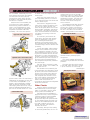
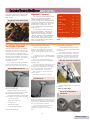
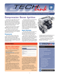
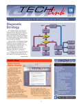
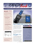
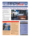
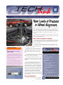
August 2001
Volume 3, No. 8
Wheel alignment is a traditional customer concern, frequently mentioned on JD Power surveys as a customer dissatisfier. Unsatisfactory alignment shows up as customer concerns such as abnormal tire wear and handling discrepancies -for instance, pulling or poor tracking. Customers also comment
if the steering wheel is angled when the vehicle is going
straight.
When the 2002 TrailBlazer, Envoy and Bravada were in the
planning stages, engineering identified improving factory alignment as an important goal.
New Front Suspension System
The “clean sheet of paper” thinking began with an all-new
front suspension design. It follows the previous front suspension in using upper and lower control arms, but the resemblance stops there.
The upper control arm attaches to the chassis with two
bushings, and to the steering knuckle with a ball joint. There
are no adjustments
on the upper control arm.
Techline News
How Current is Your
TIS 2000?
Having the latest version of the
Techline Information System (TIS 2000)
installed on your Techline terminal is critical when you need to use your Tech 2
to program a vehicle’s Powertrain
Control Module (PCM).
GM Service Operations broadcasts a
new version of TIS 2000 over GM
ACCESS every two weeks. As long as
your dealership’s GM ACCESS system is
functioning properly, this data will be
The lower control arm pivots from an
adjustable bracket, which is attached to
the subframe with three bolts. The steering knuckle attaches with another ball
joint.
The major difference, though, is the use
of a coil-over-shock module, which joins the
lower control arm to the frame.
To minimize complexity and aid in commonizing procedures and parts, the same
suspension is used on both 2wd and 4wd
vehicles.
Front wheel alignment involves checking and setting caster, camber and toe.
Only the three bracket bolts and toe jam
nuts are involved. For caster and camber,
all you’ll need is a pry bar; no special tools
are required. Setting toe is accomplished
by the conventional method of adjusting tie
rod length. But once you understand how
the suspension is aligned in the factory,
you may have second thoughts about
realigning it arbitrarily or unnecessarily. Be
sure to check the obvious when analyzing
the customer concern before changing any
factory settings.
Contents
New Levels of Precision in Wheel Alignment . . . . .1
Techline News
How Current is Your TIS 2000? . . . . . . . . . . . . .1
Update: J-45080 Card for Tech 2 . . . . . . . . . . . .2
SI 2000 Timesaver Tip . . . . . . . . . . . . . . . . . . .2
Sunshade Removal . . . . . . . . . . . . . . . . . . . . . .4
Using the Diagnostic Worksheet . . . . . . . . . . . . .5
Tech Tips
DRL Disable Qualifications and Process . . . . .5
Seat Belts -- An Update . . . . . . . . . . . . . . . .5
Steering Column Attachment . . . . . . . . . . . .6
Front Carpet Passenger Side Water Leak . . . .6
Using Vacuum Gauge to Diagnose
Duramax LB7 Engine . . . . . . . . . . . . . . . . . .7
TAC Tips
OnStar Static . . . . . . . . . . . . . . . . . . . . . . .7
Oil Change Light Flashes After Reset . . . . . . .7
Memory Seat Will Not Recall . . . . . . . . . . . .7
Dual Zone HVAC Temperature Variation . . . . .7
Sediment in Coolant . . . . . . . . . . . . . . . . . .7
Bulletins . . . . . . . . . . . . . . . . . . . . . . . . . . . . .8
Factory Alignment
During chassis assembly, the suspencontinued on page 3
continued on page 2
1
Service Operations
downloaded to your Techline terminal automatically. But if there is a system malfunction during the broadcast, your terminal may
not contain the latest version. For standalone customers, the latest version of TIS
2000 is also available from the GMSO website (service.gm.com).
Here’s how to check the status of your
TIS 2000. Start with the desktop displayed
on your Techline terminal.
- Locate the TIS2000 application logo and
click.
- When TIS 2000 opens, locate the toolbar at the top of the screen.
- Locate Help and click. This opens a pulldown menu.
- Locate About TIS 2000 and click.
This lists the following information (typical numbers shown in example):
- Block Point
1.3
- Data Version
7.0
- Tech 2 Version
21.005
Once you have located the version numbers, you can compare them with the numbers in the electronic TIS 2000 newsletter
found under the same Help screen mentioned above. If you do not have the latest
version of TIS 2000 installed on your
Techline Terminal, it can be downloaded
from the service.gm.com website.
– Thanks to Holly Shaw
Update: J-45080
32MB Card for
Tech 2
In the April issue of TechLink, you
read about the new J-45080 32MB card
for your Tech 2. This new card provides
3 times the storage capacity of the original card, to accommodate present and
future diagnostic and programming
applications.
Since that time, you should have
received your card. It was sent out in a
two part container, shown in the photo.
The outer brown bubble wrap envelope
contains an inner protective cardboard
sleeve.
GM TechLink is a monthly magazine
for all GM retail technicians and
service consultants providing timely
information to help increase knowledge about GM products and
improve the performance of the
service department. This magazine
is a companion to the GM Edge
publication.
Publisher & Editor:
Be sure to insert the new 32mb card
in the Tech 2 slot 0, closest to the
screen. The first time you update the
new card, you will need to use the
Custom Mode of TIS 2000, because of
startup software on the card. For later
updates, use the standard procedure. If
you have multiple cards to update, the
card copy function can be used to
update the additional cards once the
first card has been updated.
Mark Stesney
GM Service Operations
/[email protected]
TIP: Be sure you have the most current TIS 2000 software when doing the
update.
Marie Meredith
– Thanks to Mark Stesney
Technical Editor:
Jim Horner
/[email protected]
1-248-816-3641
Production Manager:
Desktop Publishing:
Greg Szpaichler, MediaWurks
/[email protected]
FAX number:
3
1-248-649-5465
SI 2000
Timesaver Tip
Write to:
When you’re looking at any SI 2000
page, particularly a long one, here’s how
to search for a term on the page. Say
you’re on a wiring schematic and you
need to locate a specific circuit. Here’s
how.
GM TechLink on the Web:
On the Internet Explorer toolbar,
locate the EDIT button and click. Then,
in the dropdown menu, locate Find (on
This Page) and click.
In the dialog box, type
the word or term you’re
looking for.
You can limit or expand
the search by checking the
Match whole word only or
Match case buttons.
Then click Find Next
and you will be taken to
the first place the term
appears on that page. Click
Find Next as many times
as needed to locate the
usage you’re looking for.
– Thanks to Lisa Scott
*
TechLink
PO Box 500
Troy, MI 48007-0500
http://service.gm.com
:
General Motors service tips ar e
intended for use by professional technicians, not a "do-it-yourselfer." They
are written to inform those techni cians of conditions that may occur on
some vehicles, or to provide information that could assist in the proper
service of a vehicle. Properly trained
technicians have the equipment, tools,
safety instructions and know-how to
do a job properly and safely. If a condition is described, do not assume
that the bulletin applies to your vehicle or that your vehicle will have that
condition. See a General Motors dealer servicing your brand of General
Motors vehicle for information on
whether your vehicle may benefit from
the information.
Inclusion in this publication is not necessarily an endorsement of the individual or the company.
Copyright© 2001 General Motors Corporation
All rights reserved.
2
Return to page 1
sion is installed. Traditionally, the front
end is aligned as the parts are installed.
For 2002, the front end is pre-positioned during chassis build, and final
alignment is done automatically when
the vehicle is complete.
Near the end of the assembly line,
you’ll find a non-contact alignment
device built by FORI Automation. It’s
used to set final alignment on each
truck. And, according to David Risner,
Alignment Coordinator at Moraine
Assembly, “This is the most precise
Upper and Lower Control Arms
to match, much less outperform, the
FORI system.
Here’s how the system works. As
you’ve probably guessed, it involves a
lot of computing power. Plus lasers and
robotic camera “eyes.”
Each vehicle is tagged with a bar
code, which contains the vehicle’s specific VIN. By scanning the bar code,
FORI can recognize and account for different models, equipment, and options.
For instance, it recognizes various tire
sizes, and even whether the vehicle has
coil springs or air springs in the rear
suspension.
venient time for a test of the audio
equipment. Again, by scanning the bar
code, FORI knows exactly what audio
equipment is present. The FORI computer communicates with the audio
receiver in the vehicle through the
ALDL connector.
The equipment that holds the steering wheel straight for the alignment
process also contains a microphone.
The FORI computer causes a signal to
be sent to the radio from an external
antenna. Each speaker in turn responds
Laser image on sidewall
As a vehicle is positioned in the
FORI station, the lasers and cameras
orient the equipment to the vehicle.
And, a steering wheel leveler is
attached to the steering wheel. Then,
the computers take over and the measurements begin, with the wheels slowly rotating.
Adjustable Lower Control Arm Bracket
process used to date. This machinery is
calibrated at the beginning of each shift,
so the results are repeatable +/- .02
degree.” Before attempting a realignment job, bear in mind that it would
take a highly skilled technician, using a
perfectly calibrated alignment bench -plus a lot of skill and a little luck -- even
Coil-Over-Shock Module
For toe and camber, a laser creates
images on the sidewall of the tire and
this is read by the cameras. The computer establishes the plane of the rotating tire and calculates the toe and camber angles. For caster, the equipment
locates to a pad on the steering knuckle
by the lower ball joint and to the slot in
the pinch bolt at the upper ball joint.
The computer than precisely calculates
the caster angle.
This checks speaker performance,
and checks for pinched wires and other
problems.
The front end is checked for caster,
cross caster, camber, cross camber, toe
in/out, and sum toe.
The entire time the vehicle spends
in the FORI station amounts to a mere
2 1/2 to 3 minutes. As a final step, a
The fasteners are loosened by the
FORI equipment, and alignment is done
by robotic servos which maneuver the
position of the lower control arm and
adjust the tie rods at the same time.
The computer even accounts for the
lash in the steering system when setting toe, to ensure a level steering
wheel. Then the fasteners are
retorqued to specification and alignment
results are rechecked.
and the sound is picked up by the
microphone.
continued on page 4
FORI Inspection Station
Other Checks
Once the vehicle’s orientation has
been determined for front end alignment, it is possible to use the same
data for precision headlamp aim.
The beam from the headlamps is
projected into a lens, which recognizes
a different image for each headlamp
(they vary between vehicle lines
because the lamps are styled differently). The operator places an electric nutrunner on the headlamp adjusters and
the FORI computer controls the
amount, direction, and speed the
adjusters are turned.
And finally, although it has nothing
to do with alignment data, this is a con-
SERVO
BRACKET
BOLT SOCKETS
3
Return to page 1
print-out is created showing the actual
alignment results and it’s attached to
plant records.
Steering Wheel Leveler with Microphone
Alignment Concerns
The FORI system will deliver quality
settings. According to GM Brand
Quality Manager Jeff Downing, “If a
customer expresses an alignment-related concern, realignment is not the logical best place to start. First, check the
simple things: tire pressure, road
crown, and damage caused by impact
to the vehicle.”
If an alignment is performed, be
sure your equipment is precisely calibrated before beginning. The repair
order hard copy should contain the
“before” settings actually observed and
the corrected “after” setting. Repair
orders will be requested through the
WPC and compared with the plant settings and specifications.
Sunshade Removal
There are several methods of attaching
sunshades (sun visors) to vehicles. The
traditional one uses two or three screws
to retain the pivot. A different design
uses a retainer on the shaft that engages
the bezel on the headliner. This design is
used on 1997 to current Buick Century
and Regal, and 1998 to present
Oldsmobile Intrigue.
If you use the incor rect removal procedure or the incorrect tools, you will
break the visor or cause cosmetic damPivot slot aligned with visor slot
Camber
-.5
+/- .5
Cross Camber
0.0
+/- .2
+3.25
+/- .5
Cross Caster
0.0
+/- .2
Toe
+.1
+/- .2
Sum toe
+.1
+/- .2
Rear Toe & Sum Toe
0.0
+/- .4
Caster
– Thanks to Jeff Downing and David
Risner
Recommended Removal
Emergency Removal
Fold the sunshade straight down,
unlatch it, and position the end just rearward of the clip, toward the rear of the
vehicle, aligning the pivot slot and the visor
slot.
If the recommended removal does
not work, it will be necessary to destroy
the visor pivot.
Locate the slot in the sunshade retainer
on the shaft and insert a 1/4-inch flat-bladed
screwdriver.
TIP: A piece of electrical tape on the
shaft of the tool will help avoid damaging
the plastic parts.
Use a 3/8-inch drill bit to drill out the
pivot as shown in the photo. This will
destroy the triangular lock in the bezel.
Then, rotate the visor toward the side
window to remove the pivot from the
Emergency removal using 3/8-inch drill
Hold the screwdriver stationary and pull
the sunshade downward and rotate with
enough force to duplicate the visual appearance in the photograph. Rotate about 4
inches toward the rear of the vehicle.
TIP: The first lock will be heard or felt
when it unlocks.
This will free the first lock from the
Screwdriver in slot.
bezel.
Obtain a replacement visor and bezel
and install.
– Thanks to Wayne Zigler
age to the plastic parts.
Bulletin 73-16-18 was released on
this subject several years ago, and will
soon be revised and re-released.
Bezel on left showing drilled out
triangular lock
The correct procedure is also spelled
out in detail in SI 2000. Follow this path:
- “Build” the vehicle
- Body and Accessories
- Interior Trim
- Repair Instructions
- Sunshade Replacement
Here are the highlights.
bezel on the headliner. Push the visor to the
headliner while maintaining the screwdriver
in the correct position and continue rotating
the visor toward the side window.
Pull the retainer from the bezel and
disconnect the electrical wires if
equipped with lighted visor vanity mir-
rors.
4
Return to page 1
Tips, Tricks and Updates
Using the Diagnostic
Worksheet
In your dealership’s service department, one of the most difficult and critical lines of communication is from the service customer to the technician. The more clearly the technician understands the concern and its symptoms, the more likely the condition will be fixed right the first time.
GM Service Operations is releasing a revised Diagnostic
Worksheet, based on input from GM Technical Assistance, service engineers, service manual writers, and a select group of
retail dealer service directors. The new diagnostic aid, streamlined to a single sheet, reflects today’s product without sacrificing content.
backs, aiding in customer loyalty. The GM Diagnostic
Worksheet is available in pad form from Reynolds & Reynolds
at 1.800.344.0996.
– Thanks to Chuck Burns
Service Consultants should use the Diagnostic Worksheet to
help capture a better description of the customer concern.
Technicians find these very helpful in completing quality repairs
more efficiently. They are also helpful in reducing shop come-
Seat Belts – An Update
Must seat belts be replaced
after a collision? Depends. This is
what is in SI 2000 service manuals now that will answer the question:
Daytime Running Lights
Disable Qualifications
and Process
In GM Service Operations’ continuous effort to provide the fastest customer support possible, the following process is in effect for those select governmental
agencies that request and qualify for disabling Daytime
Running Lights (DRL).
1. All requests are to be made through the Techline
Customer Support Center (TCSC) at 1.888.337.1010
(US) or 1.800.828.6860 (Canada).
2. Only the following governmental agencies qualify
for this disable request: City/State Government,
Police/Sheriff Departments, FBI, CIA, DEA, and emergency vehicles if government owned.
3. The Dealership will be required to obtain a letter
on official agency letterhead requesting the disable and
stating the reason. The letter must also include the specific VIN(s) which will be disabled and this statement:
“The DRL/Auto Headlamp system will be made fully
operational prior to disposal/sale of the vehicles listed
above.”
The letter must be kept in the service history file at
the Dealership, and a copy sent to TCSC before the disable procedures will be released. In most cases, the
vehicles will require a software change that requires a
special VCI override.
– Thanks to Bob Savo
CAUTION: Restraint systems
can be damaged in a collision. To
help avoid injury and ensure that
all parts in need of replacement
are replaced:
- Replace any seat belt sys tem that was in use during a
collision serious enough to
deploy any automatic restraint
device such as air bags and seat
belt pretensioners. This not only
includes seat belt systems in
use by people of adult size, but
seat belt systems used to secure
child restraints, infant carriers
and booster seats, including
LATCH* system and top tether
anchorages.
- Replace any seat belt sys tem that has torn, worn, or
damaged components. This not
only includes adult seat belt
systems, but built-in child
restraints and LATCH system
components, if any.
- Replace any seat belt sys tem if you observe the words
"REPLACE" or "CAUTION", or if
a yellow tag is visible. Do not
replace a seat belt system if
only the child seat caution label
is visible.
- Replace any seat belt system if you are doubtful about its
condition. This not only includes
adult seat belt systems, but
built-in child restraints, LATCH
system components, and any
restraint system used to secure
infant carriers, child restraints
and booster seats.
Do NOT replace single seat
belt system components in vehi cles that have been in a collision
as described above. Always
replace the entire seat belt system with the buckle, guide and
retractor assembly, which includes
the latch and webbing material.
After a minor collision wher e
no automatic restraint device was
deployed, seat belt system
replacement may not be necessary, unless some of the parts are
torn, worn, or otherwise dam aged.
The only way to know if a seat
belt was in use is to ask the driver/operator.
– Thanks to Jerry Garfield
*LATCH is the industry-standard acronym for the built-in child restraint
securing system -- Lower Anchorage’s and Top Tethers for Children.
LATCH consists of the top strap anchors in the vehicle, as well as the
built-in receivers for LATCH-equipped, aftermarket child restraints.
5
Return to page 1
Steering Column
Attachment
Here’s a tip that can save you a lot of
aggravation when servicing the following
vehicles:
1997 - Current
1998 - Current
2000 - Current
The square nut fits into a square
depression in the magnesium beam and
the steering column is installed onto the
stud. Then, a nut is driven onto the stud,
retaining the steering column.
Depending on carline, there may be four
or six of these studs.
beam. Then, when you attempt to install
the stud, the square nut will be pushed
out of position. It may then be necessary
to loosen and move the instrument panel
to gain access to the square nuts.
Park A venue
Seville
Steering column fastener
installed in mag beam
Bonneville and
LeSabr e
2000
DeVille
2001
Aurora
On these cars, the steering column is
attached to the magnesium instrument
panel beam with three-piece fasteners,
Steering column fastener
If the steering column needs to be
lowered, follow the instructions in
SI2000, including precautions regarding
the handling of the airbag and steering
column. Also, be sure to install J-42640
Steering Column Lock Pin into the steering column access hole in order to lock
the steering column.
consisting of a headless stud, a square
nut at the top, and a conventional nut at
the bottom.
Front Carpet
Passenger Side
Water Leak
Owners of some 1999-2001 Alero
and Grand Am models may comment
Location of foam
But when you loosen the steering
column fasteners, DO NOT simply
loosen the retaining nuts. In many cases,
the nut and stud come out as a unit,
leaving the square nut stranded in the
depression on the top side of the mag
in ambient temperatures below 32° F, the
blower may not operate due to ice.
The foam water dam under the black
beauty panel may be mis-positioned,
missing, or not adhered properly.
On vehicles with foam mispositioned or not adhered
properly
Here’s the proper method for loosening the nuts. First, install a 13 mm crowfoot wrench to the nut. Then, install a
number 7 inverted Torx socket to the
bottom of the stud. Use the Torx socket
to hold the stud while you loosen the nut
with the crowfoot wrench. This prevents
the stud from unscrewing from the
square nut. Now, when you lower the
steering column, the stud and square nut
remain in position on the magnesium
beam.
When you install the steering column,
torque the retaining nuts to 27 N.m (20 lb ft).
– Thanks to Jim Haist
On vehicles with no foam,
or with 18 mm foam and
new style beauty panel
Install 25 mm foam.
– Thanks to Ray Romeo
Old style panel, top
New style panel, bottom
Remove and discard the original foam
part. Clean the metal surface with an
alcohol based cleaner.
Install the new part, properly centering the part over the HVAC air intake
opening.
about a mildew odor, windshield fogging,
or wet carpet on the passenger side. And
On vehicles built without a
foam dam and old style
beauty panel
Install 18 mm foam.
6
Return to page 1
TAC Tips
OnStar Static
Owners of 1998 and 1999 Cadillac
Sevilles with the OnStar VS-P (handset)
system may experience a clipping type
of static noise in handsfree mode. Audio
performance through the handset will be
normal. Clipping/static should diminish as
volume is decreased.
This condition is caused by the
wrong configuration interface in the
OnStar application. Have the vehicle
reconfigured with a configuration inter face of "IPA1".
– GM Technical Assistance
✔
Howl Noise
On the 2002 TrailBlazer, Envoy and
Bravada a noise similar to a rear axle
howl may be heard. This condition may
be caused by the roof rack slats being
positioned together.
On units equipped with roof racks,
separate the roof rack slats before diagnosing a concern for a rear axle howl.
– GM Technical Assistance
✔
Oil Change Light Flashes
After Reset
On some 2001 Chevrolet and GMC
pickup and SUV models, the Oil Change
Light may continue to flash even though
reset instructions are followed. If you are
certain that you have properly followed
the Oil Light reset procedure, cycle the
ignition key 15 times. This should reset
the light.
– GM Technical Assistance
✔
Rendezvous Memory Seat
Will Not Recall Or Recalls
Exit Setting
The customer may comment that,
when using the RKE fob, the driver seat
does not recall to the Memory position
as it was stored. Instead, the seat may
recall to the Exit position or may not
move at all. Seat Recall will be turned on
in the personalization settings, and
Memory will be selected for Recall
Position.
This behavior is due to the factory
default settings. The default setting from
the factory is to have the Seat Recall set
to On and the Recall Position set to
Memory which is what the Driver Info
Center (DIC) shows. However, the
default in the Memory Seat Module for
Recall Position is set to Exit. The
Memory Seat Module does not agree
with what the DIC says. If the default
settings are never changed, the seat will
not recall to the Memory position as
expected, but will instead recall the Exit
position. Complicating the concern, if an
Exit setting has never stored by the customer, the seat will not move at all.
Here’s how to remedy it.
Go into the personalization settings,
change the Recall Position to Exit and
then exit out of the Personalization
Mode. Then, go back into personalization
settings, change the Recall Position back
to Memory and exit out again.
When you change the settings in the
DIC, a message is sent from the cluster
indicating the new setting, and the setting is then properly learned by the
Memory Seat Module. This cor rects the
condition, because the message is sent
out when the setting is changed and the
new setting is learned.
Engineering is working to get the
default settings changed at the factory to
correct this concern.
– GM Technical Assistance
mechanically functional and will sweep
with the Tech 2.
The IPM will not signal the actuator
door to swing to the proper location for
temperature control on the right side.
The Tech 2 will command the door to
swing and the door will move. However,
a Hot command results in cold air coming from the vent. The reverse is also
true.
The system uses different actuators
for the left and right sides. A left side
actuator 16164972 was installed at the
factory on the right side. To correct the
condition, install right side actuator
16163982.
– GM Technical Assistance
✔
Sediment in Coolant
Some 2002 Trailblazer, Envoy, and
Bravada models may have sediment in
the coolant bottle and other parts of the
cooling system. This may be caused by
sealer pellets added to the coolant at
assembly, to sufficiently seal possible
minor coolant leak concerns. This is a
normal condition and no service is necessary
– GM Technical Assistance
✔
✔
QuickTIP
Dual Zone HVAC
Temperature Variation
On some 2000-01 Pontiac
Bonnevilles and Buick LeSabres, there
may be a large variation side to side in
duct temperatures. There are two possible causes and corrections.
Side to side HVAC temperature
different from upper
center/outer outlets
This is caused by a low refrigerant
charge condition. The A/C system is
undercharged by 0.5 lbs. To correct the
condition, charge to the new 2.2 lb specification.
The passenger (right) blend air
door does not move.
In this condition, when you check
with your Tech 2, the commanded
counts are 45 and actual counts are 260.
No codes set in the IPM. The dual zone
option is active in the DIM. The door is
Using a Vacuum Gauge
to Diagnose Fuel
Systems on Duramax
Diesel LB7 Engines
All Chevrolet and GMC dealer ships received an essential tool
J-44638 Vacuum Gauge. It is to be
used to diagnose the supply side of
the 6600 Duramax Fuel system.
Some gauges may have been
shipped with the connections of the
gauge and valve connector loose on
the flexible hose. This condition
could cause an incorrect diagnosis
of the fuel system. Please inspect
your gauge to be sure all connections are tight and sealed with
Teflon-based sealant. Teflon tape is
not recommended.
– Thanks to Bill Carnevale
7
Return to page 1
This review of service bulletins released
through mid-July lists the bulletin number,
superseded bulletin number (if applicable),
subject and models.
J-44226-3A Modification or Replacement;
2002 Chevrolet and GMC S/T Utility
Models, 2002 Oldsmobile Bravada with
4.2L Engine (VIN S -- RPO LL8)
GENERAL INFORMATION:
01-06-04-033; Various Driveability
Symptoms -- Malfunction Indicator Lamp
(MIL) Illuminates Intermittently, DTCs
Set, Blown Fuses (Repair Wires and
Secure IP Harness); 2001 Chevrolet
Venture, Oldsmobile Silhouette, Pontiac
Montana Between VIN Breakpoints
Specified
01-00-89-008A; replaces 01-00-89008; Recreational (Dinghy) Towing;
Numerous Specified Vehicles 1995-2002
01-00-89-010; replaces 58-01-01;
Information on Use of Diagnostic
Worksheet; 2002 and Prior Model Year
Passenger Cars and Trucks
01-00-89-011; New Technical
Assistance Information Form; 2002 and
Prior Passenger Cars and Trucks
HVAC:
00-01-38-009A; replaces 00-01-38009; Refrigerant Dye Added to A/C
System at Assembly Plant; All 2001
Passenger Cars, 2002 Chevrolet Tracker
01-01-38-008; Heating, Ventilation and
Air Conditioning (HVAC) -- Normal
Operational Characteristics; 1999-2002
Chevrolet Tracker
01-01-38-009; Wet Carpet/Odor in
Passenger Foot Well Area (Repair
Evaporator Case Drain to Cowl Seal/Open
Evaporator Case Drain); 2002 Buick
Rendezvous, 2001 Chevrolet Venture,
Oldsmobile Silhouette, Pontiac Aztek,
Montana
STEERING:
01-02-32-005; Whine Noise From
Power Steering (P/S) System During
Vehicle Start-up at Low Ambient
Temperatures (Flush/Bleed P/S System,
Change P/S Fluid); 2002 Chevrolet and
GMC S/T Utility Models, Oldsmobile
Bravada With 4.2L Engine (VIN S-- RPO
LL8)
DRIVELINE AXLE:
01-04-17-001A; replaces 01-04-17001; Launch Shudder On Acceleration
(Install New One-Piece Propeller Shaft);
1999-2001 Chevrolet and GMC
K2500/3500 Extended and Crew Cab
Long box Pickup Models with Automatic
Transmission
ENGINE/PROPULSION
SYSTEM:
99-06-03-010A (replaces 99-06-03010; DTCs B1001, B1271 or B1780 Set
When Replacing/Reprogramming Other
Modules; 1999-2002 All Passenger Cars
and Trucks With Class 2 Serial Data
Communication Between Modules
01-06-01-017; Flywheel Holding Tool
01-06-04-034; Engine RPM Limited to
3000 RPM and No Cruise Control (Check
Wiring and NSBU Switch); 2001
Chevrolet and GMC C/K Pickup Models
with 8.1 L Engine (VIN G -- RPO L18) and
Allison Automatic Transmission (RPO
M74)
01-06-04-035; Non-Serviceable
Connectors on the Fuel Injector Control
Module Harness for the Duramax 6600
Diesel Engine; 2001 Chevrolet and GMC
C/K Models (2500 HD and 3500) with
6.6L Engine (VIN 1 -- RPO LB7)
01-06-04-036; Diagnosing Fuel Gauge
Reading Empty, Low Fuel Message
Displayed, DTCs Set; 2000-01 Chevrolet
and GMC C/K Utility Models with Dual
Fuel Tanks
01-06-125-001; Battery Charger
Inoperative, Check Vehicle Displayed on
Battery Charger (Reprogram BPCM);
1997-1998 Chevrolet S-10 Electric Truck
with Panasonic (TP-6) Lead Acid Battery
Pack
TRANSMISSION/TRANSAXLE:
01-07-29-004; replaces 72-05-08B;
Corvette ZF Six-Speed Manual
Transmission Service; 1989-1996
Chevrolet Corvette with ZF Six-Speed
Manual Transmission (RPO ML9)
01-07-30-023; Harsh 1-2 Upshift and
Possible Diagnostic Trouble Code (DTC)
P1870 (Replace Valve Body); various
1996-2000 Cars and Trucks with 4L60-E
Automatic Transmission (RPO M30)
BODY AND ACCESSORIES:
01-08-49-009; Revised Instrument
Panel Cluster (IPC) Replacement; 19951999 Chevrolet Cavalier and Pontiac
Sunfire
01-08-50-005; Second Row Easy
Entry 40% Rear Seat Will Not Unlock or
Release (Replace Latch Assembly); 2001
Chevrolet and GMC C/K Models with
Second Row Easy Entry 40% Seat (RPO
AT5)
01-08-52-002A; replaces 01-08-52-002;
Programming Remote Keyless Entry (RKE)
Transmitters; 2001 Chevrolet Malibu,
Oldsmobile Alero, Pontiac Grand Am
01-08-56-001A; replaces 01-08-56001;
Security Lamp Illuminated on the IP,
Engine Stalls, No Start, DTC B2960
(Security System Sensor Data Incor rect
but Valid) Set (Inspect and Repair Cause
of DTC B2960); 1998-2001 Chevrolet and
GMC S/T Pickup and Utility Models,
Oldsmobile Bravada
01-08-56-002A; replaces 01-08-56002; Security Lamp Illuminated on the IP,
Engine Stalls, No Start, DTC B2960
(Security System Sensor Data Incor rect
but Valid) Set (Inspect and Repair Cause
of DTC B2960); 1999-2001 Chevrolet and
GMC C/K Pickup and Utility Models
01-08-56-003A; replaces 01-08-56003; Security Lamp Illuminated on the IP,
Engine Stalls, No Start, DTC B2960
(Security System Sensor Data Incor rect
but Valid) Set (Inspect and Repair Cause
of DTC B2960); 1999-2001 Chevrolet and
GMC M/L Van Models
01-08-60-001; Availability of Repair
Kits and Paint for Structural Reaction
Injection Molding (SRIM) Composite Box;
2002 Chevrolet Avalanche (End Gate and
Box Front Inner Panel), 2001 Chevrolet
and GMC C/K Pickup Models (Box) with
Composite Pickup Box (RPO E37)
01-08-61-004; Corrosion of Side
Assist Step Brackets and Assist
Step/Trailer Connector Fasteners
(Replace Fasteners, Install Bracket
Shields); 2000-01 GMC S/T Jimmy
Models With Diamond Edition
Appearance Package (RPO JDE)
01-08-64-008; New Style Water
Deflector; 2000-2001 Chevrolet Impala
01-08-64-009; Door Rattle with
Moderate to High Audio System Volume
(Insulate Door Components); 1997-2001
Chevrolet Corvette
01-08-66-005; Availability fo Pickup
Box Reinforcement Kits for Toolbox/Rear
Window Barrier/Ladder Rack
Applications; 1999-2001 Chevrolet and
GMC C/K Pickup Models With Fleetside
Pickup Box (RPO E63)
01-08-66-006; Chevrolet Avalanche
Cargo Area; 2002 Chevrolet Avalanche
RESTRAINTS:
01-09-40-001; Replacement Front
Seat Belt Retractor and Buckle Usage;
1999-2002 Chevrolet and GMC C/K
Pickup Models, 2000-02 Chevrolet and
GMC C/K Utility Models, 2002 Cadillac
Escalade
01-09-40-002; Seat Belt System
Replacement Guidelines for Vehicles
Involved in Collisions; 2002 and Prior
Passenger Cars and Trucks
8
Return to page 1