1
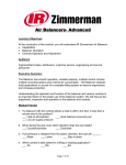
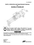
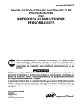
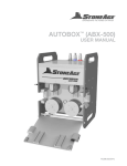
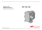
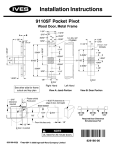
Form MHD56280
PARTS, INSTALLATION AND MAINTENANCE MANUAL
for
4 CUP VACUUM
ERGONOMIC HANDLING SYSTEM
READ THIS MANUAL BEFORE USING THESE PRODUCTS. This manual
contains important safety, installation, and maintenance information. Make
this manual available to all persons responsible for the installation, operation
and maintenance of these products.
Do not use this Handling Device for lifting, supporting, or transporting people. Do not
use the system to lift or support loads over people. Always operate, inspect and maintain
this equipment in accordance with applicable safety codes and regulations.
Equipment shown in this manual is intended for industrial use only. Use only
Ingersoll-Rand components in installation. All Ingersoll-Rand components are tested and
certified to applicable safety standards.
Form MHD56280
Edition 2
May 2005
71440150
© 2005 Ingersoll-Rand Company
CONTENTS
Description
Safety Information
Danger, Caution, Warning and Notice
Safety Summary
General Handling System Information
Principles of Balancer Operation
Specifications
Controls Operation
Interlock System (Safety Circuit)
Custom End Effector Operation
Controls Installation
Vacuum Interlock Adjustments
2
Page No.
3
3
3
4
4
4
5
5
5
5
5
Description
Interlock Test
System Troubleshooting
Preventative Maintenance
Air Supply
Wire Rope and Hook
Controls, Hose, Tube and Pipe
Handling Device
Support System
General Maintenance
Parts Drawing and Parts List
Warranty
Page No.
5
6
7
7
7
7
7
7
7
8-13
15
MHD56280 - Edition 2
SAFETY INFORMATION
This manual provides instruction for the operation and
maintenance of your Ingersoll-Rand Handling Device System.
This manual supports a fully installed system. Operators should be
familiar with the operation of the controls before using the system.
Danger, Warning, Caution and Notice
Throughout this manual there are steps and procedures which, if
not followed, may result in a hazard. The following signal words
are used to identify the level of potential hazard.
Indicates an imminently
hazardous situation which, if
not avoided, will result in
death or serious injury.
Indicates a potentially
hazardous situation which, if
not avoided, could result in
death or serious injury.
Indicates a potentially
hazardous situation which, if
not avoided, may result in
minor or moderate injury or
property damage.
Indicates information or a
company policy that relates
directly or indirectly to the
safety of personnel or
protection of property.
Safety Summary
• Noncompliance, either in full or in part, with the operational
directions marked with this symbol can result in injury,
property or material damage. Danger, Warning and Caution
notices must be strictly adhered to.
• The manufacturer has attempted to detail in this manual all
areas of possible danger to personnel concerning the use of
this equipment. However, personnel should use caution when
installing, commissioning, adjusting, operating, and servicing
this equipment.
• The manufacturer is not liable for any damage or injury
arising from a workers failure to follow the instructions
contained in this manual and failure to exercise due care and
caution in the adjustment, installation, operation, service of
this equipment. The following safety information should be
carefully read and followed.
• Personal protective and safety equipment required by the
operator's surrounding environment must be used and
maintained in accordance with the manufacturer's
instruction.
Ingersoll-Rand recognizes that most companies who use
Ingersoll-Rand H/D Systems have a safety program in force at
their facility. In the event that some conflict exists between a rule
set forth in this publication and a similar rule already set by an
individual company, the more stringent of the two should take
precedence.
Safe Operating Instructions are provided to make an operator
aware of dangerous practices to avoid and are not necessarily
limited to the following list. Refer to specific sections in the
manual for additional safety information.
1. Only allow personnel trained in safety and operation of this
rail system to operate and maintain this system.
2. When a “DO NOT OPERATE” sign is placed on the H/D,
do not use until repairs or adjustments have been completed
and the sign has been removed by designated personnel.
3. Before each shift, visually check the H/D for wear and
damage. Never use a H/D that inspection indicates is worn or
damaged.
4. Check interlock circuit at first operation of the day.
5. Never exceed the rated capacity of the H/D. Refer to labels
attached to the H/D.
6. Pay attention to loads suspended from the H/D at all times.
7. Make sure everyone is clear of the load path. Do not lift a
load over people.
8. Use good posture when operating H/D.
9. Do not swing a suspended load.
10. Check air connections for leakage.
11. Never suspend a load for an extended period of time.
12. Never leave a suspended load unattended.
13. Never weld or cut a load suspended from the H/D.
14. Do not operate H/D if jamming, overloading, or binding
occurs.
15. Avoid collision or bumping of suspended components on the
H/D.
• If the part(s) is not held securely by the H/D and slips off the
vacuum cups, the empty H/D will rise rapidly with the
approximate force required to support the H/D and part(s).
• If system air pressure is lost, lower the H/D immediately. The
operator must stay out of the vertical path of the H/D and
part(s). The vacuum may lose the force required to hold the
part(s) resulting in injury.
• The Custom End Effector will be referred to as the H/D
(Handling Device) throughout this document.
MHD56280 - Edition 2
3
GENERAL HANDLING SYSTEM INFORMATION
Ingersoll-Rand H/D Systems are a group of engineered
components designed to maximize the interaction between man
and machine. The H/D mounts to a Ingersoll-Rand support
system, articulating arm, balancer, jib crane, or aluminum and
steel rail system. The balancer has a wire rope with load hook
attached to a H/D that is used to lift and manipulate the part(s).
The operator controls the system by using the up/down, and
vacuum controls mounted on the H/D.
The system renders the part(s) weightless through its unique
compressed air balancer. The support system provides easy
horizontal movement, which creates a package that requires little
physical effort reducing operator fatigue.
Suspended part(s) can be moved left or right, forward or back, for
a predetermined distance, from a pick up point to a set down point.
The suspended part(s) can be raised or lowered approximately
twelve inches (300 mm) from which it has been raised by gently
nudging the load up or down. This is known as floating. Use of the
controls is not required for this, just pressure applied to the H/D
and parts by the operator in the desired direction.
This manual provides necessary information for the
Ingersoll-Rand Ergonomic Handling System.
While its scope cannot be complete unless addressing a specific
system in a specific environment, it provides the installer and
operator a clearer picture of the systems that can be assembled
with Ingersoll-Rand equipment and accessories.
Principles of Balancer Operation
The power source for the balancer is compressed air. A minimum
of 70 psi (4.8 bar) is recommended, 100 psi (6.9 bar) maximum.
The balancer reaches maximum capacity when 100 psi (6.9 bar) is
applied, as air pressure decreases the unit capacity decreases
proportionally. If 80 psi (5.5 bar) is applied to the balancer you
will obtain 80% of rated capacity.
For a detailed principle of operation, see the Ingersoll-Rand
Balancer Service Manual Form MHD56151.
SPECIFICATIONS
10 inch x 14 inch Vacuum Cup Configuration
5 inch x 7 inch Vacuum Cup Configuration
DN
14 inches
(36 cms)
UP
DN
7 inches
(18 cms)
UP
10 inches
(25 cms)
5 inches
(13 cms)
DN
inHg
UP
PSI
45 lbs.
99 lbs.
120 lbs.
IES
LIFTING C AP ACITY
OPE R ATING PR ESS U RE
70 PSI MA X = 100
6 inHg
25 inHg
18 inHg
MIN =
VAC UU M -
RATED L OAD CAPACIT
DN
UP
37 inches
(94 cms)
34 inches
(86 cms)
24.5 inches
(62 cms)
22.4 inches
(57 cms)
9.5 inches
(24 cms)
24 inches
(61 cms)
22 inches
(56 cms)
9 inches
(23 cms)
(Dwg. MHP2708)
4
MHD56280 - Edition 2
CONTROLS OPERATION
The ZA control package utilizes a pendant mounted to the H/D for
up and down control. A manifold mounted on the balancer,
controls the speed of the unit.
Interlock System (Safety Circuit)
Ingersoll-Rand’s Interlock is a pilot operated, adjustable spring
return valve. Pilot pressure from the balancer shifts the valve
when a load greater than that of the empty H/D is lifted. The
Interlock is available on ZA controlled H/Ds only.
When the interlock valve is shifted, the vacuum off circuit is
disabled, to prevent accidentally dropping the suspended part(s).
When the load is set down the pilot pressure from the balancer is
reduced. The valve will shift to its original state allowing the
vacuum off circuit to function and the part(s) to be released.
The following warnings and operating instructions are intended to
avoid unsafe operating practices which might lead to injury or
property damage.
Custom End Effector Operation
• If the part(s) is not held securely by the H/D and slips off the
vacuum cups, the empty H/D will rise rapidly with the
approximate force required to support the H/D and part(s).
• If system air pressure is lost, lower the H/D immediately. The
operator must stay out of the vertical path of the H/D and
part(s). The vacuum may lose the force required to hold the
part(s) resulting in falling load.
• The up/down levers operate similar to a car accelerator, the
greater the pressure the higher the speed. Use a speed that will
assure controlled movement of the H/D.
• Persons and body parts must never be in the path of the H/D.
• Proper use of the H/D prevents twisting of the wire rope and
airlines. Never turn continuously in one direction; rather
reverse direction with each cycle.
• The empty H/D should not be left suspended when
unattended. Place the H/D on a docking station, or pallet and
out of the work paths.
The operator moves the H/D to the pick up point and positions it to
pick up the parts.
Depress the down lever or push the H/D down to lower the H/D to
pick up the part(s). The vacuum cups should be centered on the
part(s).
The operator then actuates the vacuum “on” button and waits until
sufficient vacuum is obtained.
The H/D is equipped with the ZA control package and Interlock
circuit. It should be tested at the first operation of the day. Depress
the up lever to raise the part(s) approximately one inch (30 mm)
above the pick up point. The optional Interlock indicator will be
green. Then depress the vacuum “off” button. The vacuum off will
not function. If the part drops, notify maintenance personnel
immediately.
Depress the up lever or lift the H/D to clear the pick up point, and
transfer to the set down point.
Position the part(s) over the set down point, depress the down
lever or push the H/D down to lower the part(s) until the part(s)
contacts the set down point or the Interlock indicator is clear.
Depress and hold the vacuum “off” button until the part is
released.
Once the part(s) has been released, depress the up lever or lift the
H/D as necessary to clear the set down point and part(s). Release
vacuum “off” button and transfer H/D to pick up point.
Controls Installation
• Safe installation and operation of Ingersoll-Rand equipment
depends on you. Read all instructions before starting work on
the system.
• The suspended H/D and part(s) may be raised and lowered
simply by exerting force in the desired direction.
• Operators must be trained in the proper use and operation of
the H/D
Refer to the Ingersoll-Rand Balancer Service Manual Form
MHD56151 for detailed instructions.
Purge the air supply for a minimum of 30 seconds prior to the
connection of the control package to remove any debris from
airlines. This will help prevent damage to controls at start up.
Install the balancer on the support system. Install the control
package to the Ingersoll-Rand Balancer.
Vacuum Interlock Adjustments
• It may be necessary to depress the vacuum “on”, vacuum
“off” buttons several times to obtain the correct interlock
setting.
• The interlock should not be adjusted until the ZA control
adjustments have been completed.
1.
2.
3.
4.
Interlock Test
1.
2.
3.
4.
MHD56280 - Edition 2
Suspend the empty H/D from the balancer at mid travel.
Adjust the interlock adjustment screw counterclockwise until
approximately 1-1/2 inch (38 mm) of thread is visible.
Adjust the interlock adjustment screw clockwise and depress
vacuum “off” button repeatedly until the vacuum turns off.
Depress the vacuum “on/off” buttons several times to ensure
smooth consistent operation of the vacuum circuit. Ensure
the interlock valve is shifting completely.
Depress the vacuum button to turn on the vacuum.
Raise the H/D to its maximum up position.
Increase the pressure in the balancer by depressing the up
lever, 3 or 4 seconds.
Depress the vacuum “off” button. The vacuum should remain
constant.
5
5.
6.
If the vacuum turns off repeat steps 1 through 4 of the
Interlock Adjustments and repeat Interlock Test.
Depress the down lever and the vacuum “off” button
simultaneously when the H/D begins to lower the vacuum
should shut off.
Once the interlock valve is adjusted correctly, hold the interlock
adjustment stem with a suitable pair of pliers and tighten the jam
nut on the interlock adjustment screw to prevent the setting from
changing.
• Repeat the Interlock Test to ensure the setting did not change
when the jam nut was tightened.
SYSTEM TROUBLESHOOTING
This troubleshooting chart will cover only H/D specific problems. Problems relating to the balancer, controls, or support system will be
covered in the applicable manual.
Problem
Vacuum does not function consistently
or not function at all
Interlock does not prevent vacuum from
shutting off.
Part(s) shift or slip with vacuum
engaged
6
Probable Cause
Debris in air lines or fittings.
Probable Solution
Remove debris.
Flush air lines.
Loose or broken air lines or fittings.
Tighten connections or replace air lines or fittings.
Improper interlock adjustment.
Refer to Adjustment Procedures.
Faulty vacuum button.
Replace vacuum button.
Faulty vacuum valve.
Replace vacuum valve.
Faulty vacuum cup.
Replace vacuum cup.
Damaged wire rope.
Replace wire rope.
Debris in air lines or fittings.
Remove debris.
Flush air lines.
Loose or broken air lines or fittings.
Tighten connections or replace airlines or fittings.
Improper interlock adjustment.
Refer to Adjustment Procedures.
Faulty Interlock valve.
Replace Interlock valve.
Deteriorated, loose or torn vacuum
cup(s).
Tighten or replace vacuum cup(s).
Insufficient air supply pressure
Adjust air supply to the highest maintainable
pressure.
MHD56280 - Edition 2
PREVENTATIVE MAINTENANCE
The purpose of the preventative maintenance recommendations is
to prevent unexpected breakdowns and unnecessary wear by
periodically inspecting, cleaning, and testing the balancer, support
system, and H/D. Inspection intervals should be based on the type
of environment and frequency of usage. Operating the system in a
dirty environment or frequent usage will require a shorter interval
between inspections and maintenance.
Inspect the control manifold/regulator for leakage at adjustment
screws, and the valve body. Ensure the manifold/regulator is
properly connected to the balancer end cap. Repair or replace as
necessary, refer to the Ingersoll-Rand Balancer Service Manual
Form MHD56151.
A Preventative Maintenance Program should be developed based
on the following information and use of the H/D.
1.
2.
3.
Air Supply
A clean, dry, oil and rust free air supply is the most important
factor in proper system operation, and serviceability. In-line air
oilers / lubricators should never be installed on the balancer’s air
supply. Oil will damage the controls, causing erratic and sluggish
operation of the system. An airline regulator and five (5) micron
filter are recommended to improve the quality of air to the
balancer and H/D. The balancer is designed to attain maximum
capacity at 100 psi (6.9 bar). If the system pressure is above100
psi (6.9 bar), damage to the controls or balancer may occur.
Handling Device (H/D)
4.
5.
6.
Inspect all welds for cracks.
Inspect all fasteners for security.
Inspect all bearings and rotating parts for smooth operation
and proper lubrication.
Check all valves for leakage.
Inspect the vacuum circuit for proper operation and sufficient
vacuum indication.
Inspect the interlock circuit for leakage and test for proper
operation.
Support System
Refer to applicable manual for proper inspection and preventative
maintenance procedures.
Wire Rope and Hook
General Maintenance
• Load hook or wire rope should be replaced with
Ingersoll-Rand replacement parts only.
Inspect wire rope daily for wear by the operator. Wire rope that is
bulging, frayed, or worn excessively should be reported to your
maintenance personnel for replacement.
Inspect hooks for wear and ease of rotation. Ensure that the hook
gate closes completely and locks. Hooks that do not lock must be
replaced.
Controls, Hose, Tube and Pipe
Inspect all hose, tube, and pipe for leakage, kinks, and proper
connection. Tighten all connections or replace damaged air lines
or fittings. This will keep equipment from drifting or sluggish
operation.
Inspect the H/D control handles for leaks at tube connections,
valves, pushbuttons, and levers. Inspect handles for cracks,
missing hardware and deteriorated grips. Repair or replace as
necessary.
• The interlock valve must be adjusted and tested prior to
putting the H/D into production.
• Prior to any maintenance being performed the system air
supply should be shut off and locked out.
• The load cable of the balancer should be slack.
• Use Ingersoll-Rand replacement parts only.
Labeling all air lines with valve and port number or location prior
to disconnection will ease reassembly of H/D.
1. Lower H/D to the floor or a suitable work surface.
2. Turn off and lock out the system air supply.
3. Depress the down lever until all air has exhausted from the
balancer and the wire rope is slack.
4. Remove the H/D from the hook.
5. Label and disconnect the air lines at the top of the H/D.
6. Ensure all cable ties are removed prior to any component
removal and replaced upon completion of tasks.
ICE NOTES
MHD56280 - Edition 2
7
CARTON H/D PNEUMATIC SCHEMATIC DRAWING
BALANCER
MAIN SUPPLY
3/8" CLEAR
DOWN UP
6
24
7
2
3
4
3/8" BLACK
1
8
V
V
DN UP
Y (MAIN SUPPLY)
3/8" YELLOW
5/32" W
23
1
Y (INTERLOCK)
9
ZA HANDLE
9
3/8" YELLOW
5/32" W
3/8" YELLOW
9
10
1/4" YELLOW
12
12
15
5/32" B
G
9
5/32" G
11
14
12
16
17 13
18
19 13
19 13
19 13
21
22
20
13
(Dwg. MHP2633)
8
MHD56280 - Edition 2
CARTON H/D PNEUMATIC SCHEMATIC PARTS LIST
Item No.
Description of Part
Total Qty.
Part Number
1
Tube
2
93977
2
Shut Off Valve
1
90362
3
Check Valve
1
13270
4
Fitting, Tee
1
10718
6
Interlock Valve
1
99064
7
Fitting, Elbow
1
93972
8
Fitting, Elbow
1
93970
9
Fitting, Elbow
7
93969
10
“Y” Push on Fitting
1
99159
11
Poppet Valve
2
93849
12
Fitting, Elbow
2
93978
13
PIAB Hose Clamp
14
16012262
14
Indicator Light - Green
1
93861
15
Pilot Valve
1
16012197
16
PIAB Vacuum Pump
1
97306379
17
PIAB Fitting
1
16012205
18
PIAB Hose
1
16012213
19
PIAB “T” Fitting
3
16012221
20
PIAB Fitting
4
16012239
21
MCMASTER - CARR Fitting
4
16012239
22
MCMASTER - CARR Fitting
4
16012254
23
ZA Manifold Assembly
1
15071
24
Quad-Coil Hose Assembly with Fittings
1
10813
MHD56280 - Edition 2
9
CARTON H/D ASSEMBLY DRAWING
5 inch x 7 inch Vacuum Cup Configuration
Vacuum
ON/OFF
13 14
10
11
24
45 lbs.
99 lbs.
LIFTING CAPACITY
120 lbs.
6 inHg
27 inHg
18 inHg
RATED LOAD CAPACITIES
OPERATING PRESSURE
MIN = 70 PSI - MAXSI= 100 P
VACUUM - inHg
12
25
P
DN U
1
18 19
21
24
2
3
8 9
7
6
5
4
15
16 17
22
23
(Dwg. MHP2632)
10
MHD56280 - Edition 2
CARTON H/D PARTS LIST
Item No.
Description of Part
Total Qty.
Part Number
1
4 Position Manual C.G. ~ W/C
1
87306395
2
Bail
1
87306346
3
Vacuum Pump Mounting Bracket
1
87306361
4
Swiveling Handle Assembly for Bail
1
16010662
5
Telespar Tube
1
54030507
6
Handle Pivot Sub-Assembly
1
54030499
7
Tel-Spar Tubing
1
87306387
8
Screw (5/16-18 x 1.50” LG. SHCS)
2
70936
9
Locknut (5/16-18)
2
75504
10
Handle Adapter
1
54030523
11
Bent Handle
1
99169
12
ERGO ZA Control Mounted Assembly
1
54028014
13
ERGO ZA Handle Bracket
1
99168
14
3 Port ZA Control Handle
1
18621
15
Pivot Attachment Plate
1
54025507
16
Screw (M8-1.25 x 25 mm. SHCS)
4
87306429
17
Locknut (M8-1.25)
4
87306437
18
Screw (M6-1.0 x 45 mm. SHCS)
4
87306403
19
Locknut (M6-1.0)
4
87306411
21
Mounting Bracket
1
16009854
22
Custom Template for Vacuum Cup Configuration
1
87306353
23
PIAB Vacuum Cup (Nitrile)
4
87306452
24
Vacuum Gauge Mounting Bracket
1
16012312
25
Capacity Label
1
16012320
MHD56280 - Edition 2
11
CARTON H/D ASSEMBLY DRAWING
10 inch x 14 inch Vacuum Cup Configuration
Vacuum
ON/OFF
13 14
10
11
24
45 lbs.
99 lbs.
LIFTING CAPACITY
120 lbs.
6 inHg
25 inHg
18 inHg
RATED LOAD CAPACIT
IES
OPERATING PRESSURE
MIN = 70 PSI - MAX = 100 PSI
VACUUM - inHg
12
25
P
DN U
1
18 19
21
24
2
3
8 9 7
6
5
4
15
16 17
22
23
(Dwg. MHP2634)
12
MHD56280 - Edition 2
CARTON H/D PARTS LIST
Item No.
Description of Part
Total Qty.
Part Number
1
4 Position Manual C.G. ~ W/C
1
87306395
2
Bail
1
87306346
3
Vacuum Pump Mounting Bracket
1
87306361
4
Swiveling Handle Assembly for Bail
1
16010662
5
Telespar Tube
1
54030507
6
Handle Pivot Sub-Assembly
1
54030499
7
Tel-Spar Tubing
1
87306387
8
Screw (5/16-18 x 1.50” LG. SHCS)
2
70936
9
Locknut (5/16-18)
2
75504
10
Handle Adapter
1
54030523
11
Bent Handle
1
99169
12
ERGO ZA Control Mounted Assembly
1
54028014
13
ERGO ZA Handle Bracket
1
99168
14
3 Port ZA Control Handle
1
18621
15
Pivot Attachment Plate
1
54025507
16
Screw (M8-1.25 x 25 mm. SHCS)
4
87306429
17
Locknut (M8-1.25)
4
87306437
18
Screw (M6-1.0 x 45 mm. SHCS)
4
87306403
19
Locknut (M6-1.25)
4
87306411
21
Mounting Bracket
1
16009854
22
Custom Template for Vacuum Cup Configuration
1
87306478
23
PIAB Vacuum Cup (Nitrile)
4
87306452
24
Vacuum Gauge Mounting Bracket
1
16012312
25
Capacity Label
1
16012320
16010209
TS LIST FOR 1010209
MHD56280 - Edition 2
13
PARTS ORDERING INFORMATION
Handling Systems are designed and constructed to provide long,
trouble-free service. In time it may become necessary to order and
install new parts to replace those that have been subjected to wear.
The use of other than Ingersoll-Rand replacement parts may
result in decreased performance, and may invalidate the warranty.
For prompt service and genuine Ingersoll-Rand parts, provide
your nearest Distributor with the following:
1.
2.
3.
Complete model number and serial number as it appears on
the nameplate.
Part number and part description as shown in this manual.
Quantity required.
For your convenience and future reference it is recommended that
the following information be recorded.
Model Number _______________________________________
Return Goods Policy
If it becomes necessary to return the complete Handling System or
certain parts to the factory, contact the Distributor from whom you
purchased the Handling System, or the nearest Ingersoll-Rand
Distributor in your locality, Ingersoll-Rand will not accept any
returned goods for warranty or service work unless prior
arrangements have been made and written authorization has been
provided from the location where the goods were purchased.
• Continuing improvement and advancement of design may
cause changes to this Handling System which are not included
in this manual. Manuals are periodically revised to
incorporate changes. Always check the manual edition
number on the front cover for the latest issue.
Disposal
Serial Number ________________________________________
Date Purchased _______________________________________
When the life of the Handling System has expired, it is
recommended that the Handling System be disassembled,
degreased and parts separated as to materials so that they may be
recycled.
SERVICE AND MAINTENANCE
For additional information contact:
Ingersoll-Rand
U.S. and International Sales
1872 Enterprise Drive
Rochester Hills, MI 48309
Phone: (248) 293-5700
Fax: (248) 293-5800
For additional information on related products order publication by the referenced Part/Document Number listed:
14
Product
Part/Document Number
Balancer Service Manual
MHD56151
MHD56280 - Edition 2
WARRANTY
The Company warrants that the Equipment manufactured by it and
delivered hereunder will be free of defects in material and
workmanship for a period of twelve months from the date of
placing the Equipment in operation or eighteen months from the
date of shipment, whichever shall first occur. Separately sold parts
are warranted for a period of six months from date of shipment.
The Purchaser shall be obligated to promptly report any failure to
conform to this warranty, in writing to the Company within said
period, whereupon the Company shall, at its option, correct such
nonconformity, by suitable repair to such Equipment or, furnish a
replacement part F.O.B. point of shipment, provided the Purchaser
has stored, installed, maintained and operated such Equipment in
accordance with good industry practices and has complied with
specific recommendations of the Company. Accessories or
equipment furnished by the Company, but manufactured by
others, shall carry whatever warranty the manufacturers have
conveyed to the Company and which can be passed on to the
Purchaser. The Company shall not be liable for any repairs,
replacements, or adjustments to the Equipment or any costs of
labor performed by the Purchaser or others without the Company's
prior written approval.
The effects of corrosion, erosion and normal wear and tear are
specifically excluded. Performance warranties are limited to those
specially stated within the Company's proposal.
The company makes no other warranty or representation of
any kind whatsoever, expressed or implied, except that of title,
and all implied warranties of merchantability and fitness for a
particular purpose, are hereby disclaimed.
Correction by the Company of nonconformities whether patent or
latent, in the manner and for the period of time provided above,
shall constitute fulfillment of all liabilities of the Company for
such nonconformities, whether based on contract, warranty,
negligence, indemnity, strict liability or otherwise with respect to
or arising out of such Equipment.
The Purchaser shall not operate Equipment which is considered to
be defective, without first notifying the Company in writing of its
intention to do so. Any such use of Equipment will be at the
Purchaser's sole risk and liability.
Limitation of Liability
The remedies of the purchaser set forth herein are exclusive, and
the total liability of the company with respect to this contract or
the equipment and services furnished hereunder, in connection
with the performance or breach thereof, or from the manufacture,
sale, delivery, installation, repair or technical direction covered by
or furnished under this contract, whether based on contract,
warranty, negligence, indemnity, strict liability or otherwise, shall
not exceed the purchase price of the unit of equipment upon which
such liability is based.
MHD56280 - Edition 2
The company and its suppliers shall in no event be liable to the
purchaser, any successors in interest or any beneficiary or assignee
of this contract for any consequential, incidental, indirect, special
or punitive damages arising out of this contract or any breach
thereof, or any defect in, or failure of, or malfunction of the
equipment hereunder, whether based upon loss of use, lost profits
or revenue, interest, lost goodwill, work stoppage, impairment, of
other goods, loss by reason of shutdown or non-operation,
increased expenses of operation, cost of purchase of replacement
power or claims of purchaser or customers of purchaser for service
interruption whether or not such loss or damage is based on
contract, warranty, negligence, indemnity, strict liability or
otherwise.
15
www.irco.com