1
Tools Required
11/32”, ¼”, and 3/8” long handle nut drivers
Pliers
Small screwdriver or IC removal tool
Optional Tools Required for “low coins” screw installation
Drill
5/16” drill bit
Installation Instructions
1. Unplug the power cord from the wall and open the door of the changer.
2. Remove the BA50 bill transport by unplugging the harness at the 15-position harness
connector. A 12-inch harness will still be connected to the side of the BA50 transport.
3. Remove the bill box from the stacker assembly.
4. Remove the stacker assembly by unscrewing the two ¼” screws at the top of the
assembly. It may be necessary to hold the nuts under the assembly with a pair of
pliers. [For changers with a dual stacker remove the two ¼” screws that secure the
stacker assembly base to the bill box bracket. The bill box bracket can remain in the
changer] Disconnect the harness from the upper rear right hand side. Slide the
stacker assembly forward out of the changer. Replace the upper two screws and nuts.
The original stacker harness will not be connected to any component.
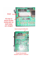
5. Set the dip switches on the 120 volt Mars validator per the label on the kit Module.
6. Unplug the 9 position harness at the Coin Acceptor Assembly.
7. Insert the 9 position harness from the new Module into the open connector. This kit is
not designed for use in a changer that accepts coins. The 9 position female connector
on the Coin Acceptor Assembly will remain open. If you need to accept coins, please
contact us for a coin interface kit.
8. Remove the three hoppers from the Coin Dispenser Assembly 6-50275-10.
9. Unbolt the Coin Dispenser Assembly by removing both 3/8” bolts.
10. Pivot the assembly forward, it does not need to be removed. [If you are having trouble
connecting the new harness you may wish to disconnect the harness from the Coin
Dispenser Assembly so it can be removed.]
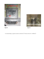
11. Feed the harness with the two 3 position connectors from the Module through the barrier
wall toward the left wall of the changer. There is a large hole with an insulating ring
toward the upper rear of the wall.
12. Unplug the main power harness from the connector at the far left of the Power Control
Center Assembly (65042606).
13. Plug the 3 position male plug from the Module into the now open connector on the
Power Control Center Assembly. Plug the machine harness into the female side of the
harness.
14. Set the Coin Dispenser Assembly back into place and secure using both bolts. If the
harness was disconnected be sure to reconnect the harness.
15. Replace the 3 hoppers.
16. Remove the factory installed black plastic mask from the Mars validator, it is held in
place with 4 screws. Install the mask from the parts kit that has the upper section
removed.
17. Mount the validator onto the metal validator slide plate; the four 11-32 keps nuts are
supplied with the validator. A 12 inch factory harness may be connected to the validator
when it is removed from the box. Unplug this harness, as it is not used with the kit. If