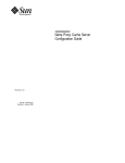
1
Ultra™ Enterprise™ 3000 System
Installation Guide
The Network Is the Computer™
Sun Microsystems Computer Company
2550 Garcia Avenue
Mountain View, CA 94043 USA
415 960-1300
fax 415 969-9131
Part No.: 802-6050-10
Revision A, May 1996
Copyright 1996 Sun Microsystems, Inc. 2550 Garcia Avenue, Mountain View, California 94043-1100 U.S.A.
All rights reserved. This product or document is protected by copyright and distributed under licenses restricting its use, copying, distribution,
and decompilation. No part of this product or document may be reproduced in any form by any means without prior written authorization of
Sun and its licensors, if any.
Portions of this product may be derived from the UNIX® system and from the Berkeley 4.3 BSD system, licensed from the University of
California. UNIX is a registered trademark in the United States and in other countries and is exclusively licensed by X/Open Company Ltd.
Third-party software, including font technology in this product, is protected by copyright and licensed from Sun’s suppliers.
RESTRICTED RIGHTS LEGEND: Use, duplication, or disclosure by the government is subject to restrictions as set forth in subparagraph (c)(1)(ii)
of the Rights in Technical Data and Computer Software clause at DFARS 252.227-7013 and FAR 52.227-19.
Sun, Sun Microsystems, the Sun logo, Solaris, Solstice, SyMON, OpenBoot, Enterprise, SunVTS, Ultra, UltraComputing, UltraServer, and
UltraSPARC are trademarks or registered trademarks of Sun Microsystems, Inc. in the United States and in other countries. All SPARC
trademarks are used under license and are trademarks or registered trademarks of SPARC International, Inc. in the United States and in other
countries. Products bearing SPARC trademarks are based upon an architecture developed by Sun Microsystems, Inc.
The OPEN LOOK® and Sun™ Graphical User Interfaces were developed by Sun Microsystems, Inc. for its users and licensees. Sun
acknowledges the pioneering efforts of Xerox Corporation in researching and developing the concept of visual or graphical user interfaces for the
computer industry. Sun holds a nonexclusive license from Xerox to the Xerox Graphical User Interface, which license also covers Sun’s licensees
who implement OPEN LOOK GUIs and otherwise comply with Sun’s written license agreements.
X Window System is a trademark of X Consortium, Inc.
THIS PUBLICATION IS PROVIDED “AS IS” WITHOUT WARRANTY OF ANY KIND, EITHER EXPRESS OR IMPLIED, INCLUDING,
BUT NOT LIMITED TO, THE IMPLIED WARRANTIES OF MERCHANTABILITY, FITNESS FOR A PARTICULAR PURPOSE, OR
NON-INFRINGEMENT.
Copyright 1996 Sun Microsystems, Inc., 2550 Garcia Avenue, Mountain View, Californie 94043-1100 U.S.A.
Tous droits réservés. Ce produit ou document est protégé par un copyright et distribué avec des licences qui en restreignent l’utilisation, la copie
et la décompilation. Aucune partie de ce produit ou de sa documentation associée ne peut être reproduite sous aucune forme, par quelque moyen
que ce soit, sans l’autorisation préalable et écrite de Sun et de ses bailleurs de licence, s’il y en a.
Des parties de ce produit pourront être derivées du système UNIX® et du système Berkeley 4.3 BSD licencié par l’Université de Californie. UNIX
est une marque enregistrée aux Etats-Unis et dans d’autres pays, et licenciée exclusivement par X/Open Company Ltd. Le logiciel détenu par des
tiers, et qui comprend la technologie relative aux polices de caractères, est protégé par un copyright et licencié par des fournisseurs de Sun.
Sun, Sun Microsystems, le logo Sun, Solaris, Solstice, SyMON, OpenBoot, Enterprise, SunVTS, Ultra, UltraComputing, SunVTS, UltraServer, et
UltraSPARC sont des marques déposées ou enregistrées de Sun Microsystems, Inc. aux Etats-Unis et dans d’autres pays. Toutes les marques
SPARC, utilisées sous licence, sont des marques déposées ou enregistrées de SPARC International, Inc. aux Etats-Unis et dans d’autres pays. Les
produits portant les marques SPARC sont basés sur une architecture développée par Sun Microsystems, Inc.
Les utilisateurs d’interfaces graphiques OPEN LOOK® et Sun™ ont été développés de Sun Microsystems, Inc. pour ses utilisateurs et licenciés.
Sun reconnaît les efforts de pionniers de Xerox Corporation pour la recherche et le développement du concept des interfaces d’utilisation visuelle
ou graphique pour l’industrie de l’informatique. Sun détient une licence non exclusive de Xerox sur l’interface d’utilisation graphique, cette
licence couvrant aussi les licenciés de Sun qui mettent en place les utilisateurs d’interfaces graphiques OPEN LOOK et qui en outre se
conforment aux licences écrites de Sun.
Le système X Window est un produit du X Consortium, Inc.
CETTE PUBLICATION EST FOURNIE "EN L’ETAT" SANS GARANTIE D’AUCUNE SORTE, NI EXPRESSE NI IMPLICITE, Y COMPRIS, ET
SANS QUE CETTE LISTE NE SOIT LIMITATIVE, DES GARANTIES CONCERNANT LA VALEUR MARCHANDE, L’APTITUDE DES
PRODUITS A REPONDRE A UNE UTILISATION PARTICULIERE OU LE FAIT QU’ILS NE SOIENT PAS CONTREFAISANTS DE PRODUITS
DE TIERS.
Please
Recycle
Contents
1. Preparing for Installation . . . . . . . . . . . . . . . . . . . . . . . . . . . . . .
1-1
1.1 Unpacking and Preparing the System . . . . . . . . . . . . . . . .
1-2
1.2 Shipping and Storing the System . . . . . . . . . . . . . . . . . . . .
1-3
1.3 Preparing the Electrical Circuits . . . . . . . . . . . . . . . . . . . . .
1-3
1.4 Preparing the Air Conditioning . . . . . . . . . . . . . . . . . . . . .
1-4
1.5 Preparing the Ethernet Network . . . . . . . . . . . . . . . . . . . .
1-4
1.6 Preparing the Area . . . . . . . . . . . . . . . . . . . . . . . . . . . . . . . .
1-6
1.7 Using the User Naming Area . . . . . . . . . . . . . . . . . . . . . . .
1-7
2. Cabling the System. . . . . . . . . . . . . . . . . . . . . . . . . . . . . . . . . . . .
2-1
2.1 Preparing the System for Cabling. . . . . . . . . . . . . . . . . . . .
2-1
2.2 Connecting the Power Cord . . . . . . . . . . . . . . . . . . . . . . . .
2-1
2.3 Connecting the Network Cable to the System . . . . . . . . .
2-4
2.4 Connecting the System to the Network . . . . . . . . . . . . . . .
2-5
2.5 Connecting an ASCII Terminal . . . . . . . . . . . . . . . . . . . . . .
2-7
2.6 Connecting the Fiber Cable to the I/O Board . . . . . . . . . .
2-9
iii
2.7 Connecting External SCSI Devices . . . . . . . . . . . . . . . . . . . 2-10
3. Powering the System On and Off . . . . . . . . . . . . . . . . . . . . . . .
3-1
3.1 Using JumpStart Automatic Installation . . . . . . . . . . . . . .
3-1
3.2 Powering On the System . . . . . . . . . . . . . . . . . . . . . . . . . . .
3-2
3.2.1 Reading Boot Messages . . . . . . . . . . . . . . . . . . . . . . .
3-5
3.2.2 Interpreting Status LED Patterns . . . . . . . . . . . . . . .
3-6
3.3 Powering Off the System . . . . . . . . . . . . . . . . . . . . . . . . . . .
3-8
4. Using the Software . . . . . . . . . . . . . . . . . . . . . . . . . . . . . . . . . . . .
4-1
4.1 Operating System Software. . . . . . . . . . . . . . . . . . . . . . . . .
4-1
4.2 Solstice SyMON Software . . . . . . . . . . . . . . . . . . . . . . . . . .
4-1
Index . . . . . . . . . . . . . . . . . . . . . . . . . . . . . . . . . . . . . . . . . . .
iv
Ultra Enterprise 3000 System Installation Guide—May 1996
Index-1
Figures
Figure 1-1
Enterprise 3000 System . . . . . . . . . . . . . . . . . . . . . . . . . . . . . . . . .
1-2
Figure 1-2
Types of Network Cables Used . . . . . . . . . . . . . . . . . . . . . . . . . .
1-5
Figure 1-3
Example of 10/100BASE-T (Twisted-Pair) Ethernet . . . . . . . .
1-5
Figure 1-4
Standalone Server Access Areas — Top View . . . . . . . . . . . . .
1-7
Figure 2-1
Key Switch Standby Position . . . . . . . . . . . . . . . . . . . . . . . . . . . .
2-2
Figure 2-2
AC Power Switch, Power Receptacle, and Retainer Clip . . . .
2-3
Figure 2-3
Network Cable . . . . . . . . . . . . . . . . . . . . . . . . . . . . . . . . . . . . . . . .
2-4
Figure 2-4
10/100BASE-T Ethernet Connection . . . . . . . . . . . . . . . . . . . . .
2-4
Figure 2-5
Connecting Twisted Pair Ethernet to N-type Coaxial Cable. .
2-6
Figure 2-6
Ethernet Cabling Length — Example Using N-type Cable. . .
2-7
Figure 2-7
Clock Board . . . . . . . . . . . . . . . . . . . . . . . . . . . . . . . . . . . . . . . . . .
2-8
Figure 2-8
Fiber Cable and Fibre Card Connectors and Ports
on the I/O Board . . . . . . . . . . . . . . . . . . . . . . . . . . . . . . . . . . . . . .
2-9
Figure 2-9
Onboard SCSI Connector on the I/O Board . . . . . . . . . . . . . . .
2-11
Figure 3-1
Key Switch Positions . . . . . . . . . . . . . . . . . . . . . . . . . . . . . . . . . . .
3-3
Figure 3-2
AC Power and Clock Board . . . . . . . . . . . . . . . . . . . . . . . . . . . . .
3-4
Figure 3-3
CPU Reset Switch on Clock Board . . . . . . . . . . . . . . . . . . . . . . .
3-5
v
Figure 3-4
vi
System Status LEDs. . . . . . . . . . . . . . . . . . . . . . . . . . . . . . . . . . . .
Ultra Enterprise 3000 System Installation Guide—May 1996
3-7
Tables
Table 2-1
Ethernet Cabling Limitations for N-type Coaxial Cable . . . . .
2-6
Table 2-2
Internal SCSI Lengths (Approximate) . . . . . . . . . . . . . . . . . . . .
2-10
Table 3-1
Front Panel LED System Status . . . . . . . . . . . . . . . . . . . . . . . . . .
3-7
vii
viii
Ultra Enterprise 3000 System Installation Guide—May 1996
Preface
The Ultra™ Enterprise™ 3000 System Installation Guide provides installation
instructions for the factory-configured 4-slot system. These instructions are
designed for an experienced system administrator with networking
knowledge.
UNIX Commands
This document may not include specific software commands or procedures.
Instead, it may name software tasks and refer you to operating system
documentation or the handbook that was shipped with your new hardware.
The types of tasks that you might need to use references for includes:
•
•
•
•
Shutting down the system
Booting the system
Configuring devices
Other basic software procedures
The references you can use include:
•
Solaris 2.x Handbook for SMCC Peripherals contains Solaris™ 2.x software
commands.
•
On-line AnswerBook™ for the complete set of documentation supporting
the Solaris 2.x software environment.
•
Other software documentation and Platform Notes that you received with
your system.
ix
Typographic Conventions
The following table describes the typographic changes used in this book.
Typeface or
Symbol
Meaning
Example
AaBbCc123
The names of commands,
files, and directories;
on-screen computer output
Edit your .login file.
Use ls -a to list all files.
machine_name% You have mail.
AaBbCc123
What you type, contrasted
with on-screen computer
output
AaBbCc123
Command-line placeholder:
replace with a real name or
value
To delete a file, type rm filename.
AaBbCc123
Book titles, new words or
terms, or words to be
emphasized
Read Chapter 6 in the User’s Guide.
These are called class options.
You must be root to do this.
machine_name% su
Password:
Shell Prompts
The following table shows the default system prompt and superuser prompt
for the C shell, Bourne shell, and Korn shell.
x
Shell
Prompt
C shell
machine_name%
C shell superuser
machine_name#
Bourne shell and Korn shell
$
Bourne shell and Korn shell
superuser
#
Ultra Enterprise 3000 System Installation Guide—May 1996
Related Documents
The following documents contain topics that relate to the information
in the Ultra Enterprise 3000 System Installation Guide.
Application
Title
Part Number
Safety/EMI
Ultra Enterprise System Cabinet Regulatory Compliance Manual
802-3846
Service
Ultra Enterprise 3000 System Manual
802-3845
Software
SMCC SPARC Hardware Platform Guide
802-5341
Solstice SyMON User’s Guide
802-5355
Ultra Enterprise Expansion Cabinet Installation and Service Manual
802-6084
Ultra Enterprise Board Installation Guide
802-5030
Ultra Enterprise CPU Installation Guide
802-5031
Ultra Enterprise SIMM Installation Guide
802-5032
Ultra Enterprise Peripheral Power Supply Installation Guide
802-5033
Ultra Enterprise Power/Cooling Module (PCM) Installation Guide
802-6244
Ultra Enterprise Disk Board Installation Guide
802-6740
Options
Preface
xi
Ordering Sun Documents
SunDocsSM is a distribution program for Sun Microsystems™ technical
documentation. Easy, convenient ordering and quick delivery is available from
SunExpress™. You can find a full listing of available documentation on the
World Wide Web: http://www.sun.com/sunexpress/
Country
Telephone
Fax
United States
1-800-873-7869
1-800-944-0661
United Kingdom
0-800-89-88-88
0-800-89-88-87
France
05-90-61-57
05-90-61-58
Belgium
02-720-09-09
02-725-88-50
Luxembourg
32-2-720-09-09
32-2-725-88-50
Germany
01-30-81-61-91
01-30-81-61-92
The Netherlands
06-022-34-45
06-022-34-46
Sweden
020-79-57-26
020-79-57-27
Switzerland
155-19-26
155-19-27
Japan
0120-33-9096
0120-33-9097
Sun Welcomes Your Comments
Please use the Reader Comment Card that accompanies this document. We are
interested in improving our documentation and welcome your comments and
suggestions.
If a card is not available, you can email or fax your comments to us. Please
include the part number of your document in the subject line of your email or
fax message.
•
•
xii
Email:
[email protected]
Fax:
SMCC Document Feedback
1-415-786-6443
Ultra Enterprise 3000 System Installation Guide—May 1996
Notes, Cautions, and Warnings
Warning – This equipment contains lethal voltage. Accidental contact with
centerplane, card cage, and drive areas can result in serious injury or death.
!
Caution – Improper handling by unqualified personnel can cause serious
damage to this equipment. Unqualified personnel who tamper with this
equipment may be held liable for any resultant damage to the equipment.
Individuals who remove any outer panels or open covers to access this
equipment must observe all safety precautions and ensure compliance with
skill level requirements, certification, and all applicable local and national
laws.
Procedures contained in this document must be performed by qualified
service-trained maintenance providers.
Note – Before you begin, carefully read each of the procedures in this manual.
If you have not performed similar operations on comparable equipment, do
not attempt to perform these procedures.
Preface
xiii
xiv
Ultra Enterprise 3000 System Installation Guide—May 1996
Preparing for Installation
1
This chapter describes how to prepare your site for the Ultra Enterprise 3000
server system.
The tasks for installing the system are:
1. Unpacking the server — Chapter 1
2. Preparing the site — Chapter 1
3. Preparing the server — Chapter 1
4. Cabling — Chapter 2
5. Powering on — Chapter 3
6. Using the software — Chapter 4
Note – For information about physical specifications, electrical specifications,
and environmental requirements, refer to Appendix A, “Specifications,” in the
Ultra Enterprise 3000 System Manual.
1-1
1
Figure 1-1
Enterprise 3000 System
1.1 Unpacking and Preparing the System
Note – Inspect all shipping cartons for evidence of physical damage. If a
shipping carton is damaged, request that the carrier's agent be present when
the carton is opened. Keep all contents and packing material for the agent's
inspection.
If the system is already unpacked, go to Section 1.3, “Preparing the Electrical
Circuits.”
!
1-2
Warning – The system can weigh up to 160 lbs (73 kg). To prevent personal
injury, two people are needed to lift the system safely.
Ultra Enterprise 3000 System Installation Guide—May 1996
1
Tools
•
•
#2 Phillips screwdriver
Front door key (packed in a bag in the accessory box)
Follow graphic instructions on the shipping container to remove the system
from the container. Remove the front door key (also the keyswitch key) and
power cord from the shipping container. These are needed to power on the
system.
Note – Any unpacking instructions printed on the outside of the shipping
carton take precedence over information in this section.
1.2 Shipping and Storing the System
Save the original shipping containers and packing materials in case you need
to store or ship your system.
If you cannot store the shipping materials, recycle or dispose of the materials
properly. Consult your local recycling authority for information.
1.3 Preparing the Electrical Circuits
In planning where to place your equipment, remember that each of the
following items require access (by way of a separate power cord) to a power
outlet:
•
•
•
Enterprise 3000 system
External peripherals
Monitor used for diagnostics
The Enterprise 3000 system uses nominal input voltages of 100-120 VAC or
200-220 VAC. Sun products are designed to work with single-phase power
systems having a grounded neutral conductor.
To reduce the risk of electrical shock, do not plug Sun products into another
type of power source. Contact your facilities manager or a qualified electrician
if you are unsure what type of power is supplied to your building.
Preparing for Installation
1-3
1
1.4 Preparing the Air Conditioning
For the most reliable system operation:
•
•
The room should have sufficient air conditioning capacity to support the
cooling needs of the entire system.
The air conditioning system should have controls that prevent excessive
temperature changes.
Refer to Appendix A, “Specifications,” in the Ultra Enterprise 3000 System
Manual for environmental information.
1.5 Preparing the Ethernet Network
The Enterprise 3000 system follows the IEEE standard for 10/100BASE-T
Ethernet (twisted-pair) or MII (Media Independent Interface).
Twisted-pair cables used with Sun Microsystems products have RJ-45
connectors that resemble the smaller RJ-11 connectors used for modular
telephone cables. For twisted-pair cable length, see Chapter 2, Table 2-1.
A MII to AUI converter cable, available from Sun, enables the 10/100 Mbps
Ethernet interface to run over 10 Mbps coaxial Ethernet networks. Other MII
Ethernet connectivity products are available from third parties.
Figure 1-2 and Figure 1-3 illustrate types of network cables and possible
implementations of 10/100BASE-T Ethernet.
Set up the network using Sun or third party components. To obtain the best
results, read any applicable manufacturer instructions. Be aware that Sun
Microsystems cannot guarantee the performance of any components that are
not purchased from Sun.
1-4
Ultra Enterprise 3000 System Installation Guide—May 1996
1
Vampire tap or N-type connectors
Ethernet cable
Server
Transceiver
Transceiver drop cable
(coaxial or optical fiber)
Hardware interface
10/100BASE-T
twisted-pair cable
Figure 1-2
Types of Network Cables Used
Coaxial cable or
optical fiber
Network cable
Tap
Concentrator hub
Tap
Concentrator hub
Workstation
Server
Twisted-pair cable
Figure 1-3
Example of 10/100BASE-T (Twisted-Pair) Ethernet
Note – Multiplexer boxes require a transceiver when used with the Ethernet
applications described in this manual. Although these transceivers are
compatible with Sun equipment, Sun Microsystems does not guarantee the
performance of any component that was not purchased from Sun.
Preparing for Installation
1-5
1
Many transceivers are compatible with both level-1 and level-2 Ethernet. To
operate these transceivers with Sun equipment, set the device for level-2
operation following the manufacturer’s instructions.
Sun equipment conforms to the Ethernet 10/100BASE-T standard, which states
that the 10/100BASE-T Link Integrity Test function should always be enabled
on both the host and the hub. If you have problems verifying connection
between Sun equipment and your hub, verify that your hub also has the link
test function enabled. Refer to Section 8.6.1, “Failure of Network
Communications,” in the Ultra Enterprise 3000 System Manual (p/n 802-6051),
and refer to the manual provided with your hub.
1.6 Preparing the Area
Use the following guidelines to prepare a location for your server.
!
•
The server unit requires approximately 1.5 feet (47 cm) of space in the front
and back for access by service personnel. See Figure 1-4.
•
A minimum space of 6 inches (16 cm) is required on both sides of the server
to afford adequate air flow.
Warning – To avoid exhaust air recirculation, do not put systems or
peripherals next to each other, side by side.
•
1-6
Keep power and interface cables clear of foot traffic. Route cables inside
walls, under the floor, through the ceiling, or in protective channels. Route
interface cables away from motors and other sources of magnetic or radio
frequency interference.
Ultra Enterprise 3000 System Installation Guide—May 1996
1
1.5 feet access at rear
6 inches
on each side
Standalone
system
1.5 feet access at front
Figure 1-4
Standalone Server Access Areas — Top View
1.7 Using the User Naming Area
To display the name of the server, IP address, owner, or other important
information on the front of the machine:
1. Remove the front bezel.
Refer to Chapter 12, “Preparing for Service,” in the Ultra Enterprise 3000
System Manual (Section 12.3.1, “Front Bezel”).
2. Snap out the narrow transparent window.
From the rear side of the bezel, gently squeeze the top and bottom edges
together as you simultaneously push the transparent window out through
the front of the bezel.
3. Choose the information that will appear on the label.
Common items include the name of the server, IP address, name and contact
information for the system administrator, and the group of users that the
machine services.
4. Use the colored paper provided with the system to make a label.
The available area for the paper label is 12 mm x 150 mm (0.5 in. x 5.9 in.).
Print or write the desired information in an area this size and cut the label to
fit the transparent window.
5. Place the paper label inside the window, and snap the window back in
place from the front side of the bezel.
Preparing for Installation
1-7
1
1-8
Ultra Enterprise 3000 System Installation Guide—May 1996
Cabling the System
2
This chapter contains procedures for connecting the power cord to the AC
power supply and instructions for cabling the system.
2.1 Preparing the System for Cabling
Make sure the server is in an area that allows access to both the front and rear
of the chassis. This site should conform to site preparation guidelines and
specifications covered in Chapter 1.
2.2 Connecting the Power Cord
1. Use the handle on the front of the Enterprise 3000 system to pull the front
door open.
2. Locate the system key switch in the upper right corner, insert the key
provided with your system, and turn the key switch to (the Standby
position).
See Figure 2-1.
2-1
2
Standby
Figure 2-1
Key Switch Standby Position
3. Turn the AC power switch to Off.
This switch is at the rear of the system, on the peripheral power supply/AC
(PPS/AC) that is installed in the far left corner. See Figure 2-2.
4. Connect the female end of the power cord into the AC connector.
This connector is at the rear of the system, on the PPS/AC, just below the
AC power switch. See Figure 2-2.
5. Route the power cord through the power cord retainer clip.
A plastic clip is attached to the back support bracket. See Figure 2-2.
a. Use a Phillips screwdriver to open the plastic retainer clip.
Remove the screw.
b. Place the power cord inside the open clip.
c. Replace the screw to reattach the retainer clip to the support bracket.
2-2
Ultra Enterprise 3000 System Installation Guide—May 1996
2
6. Connect the male end of the power cord into a grounded outlet.
The outlet must be a 100-120 or 220-240 VAC 15A circuit.
AC power switch
AC connector
Support bracket
Retainer clip
Figure 2-2
!
AC Power Switch, Power Receptacle, and Retainer Clip
Caution – Do NOT turn on power to the unit yet. Doing so can cause system
damage to occur.
7. Continue with Section 2.3 and Section 2.4 to connect the system to the
network. See Sections 2.5 through 2.7 for further cabling instructions.
Cabling the System
2-3
2
2.3 Connecting the Network Cable to the System
The locations specified in the following instructions assume the use of twistedpair 10BASE-T or 100BASE-T Ethernet.
1. Locate the network cable.
Figure 2-3 shows the twisted-pair Ethernet network cable.
Figure 2-3
Network Cable
2. Connect one end of the network cable into the RJ-45 twisted-pair network
port.
For 10/100BASE-T Ethernet, the default interface port is the onboard
connector on the I/O board in slot 1. See Figure 2-4.
Ethernet port
Figure 2-4
2-4
10/100BASE-T Ethernet Connection
Ultra Enterprise 3000 System Installation Guide—May 1996
2
2.4 Connecting the System to the Network
1. Connect the network cable to a twisted-pair-to-transceiver interface box.
2. Connect the interface box with an appropriate cable to a network
transceiver.
Figure 2-5 shows a typical arrangement for connecting the system to an
Ethernet network.
3. For Ethernet cables, determine if the cable has N-type screw-on
connectors at the ends.
• If the Ethernet cable lacks N-type connectors at the ends, use a “vampire”
tap to connect the cable to the transceiver. See Figure 2-5. To connect the
cable to the transceiver, use instructions provided with the vampire tap.
• If the Ethernet cable has N-type connectors, connect the Ethernet cable to
the transceiver:
a. Screw the Ethernet coaxial cable into one of the round screw-on type
connectors on the transceiver.
Use either one of the transceiver connectors.
b. Screw the other Ethernet coaxial cable into the other round screw-on
type connector on the transceiver.
4. Determine if a terminator should be installed. Table 2-1 lists the cabling
limitations for Ethernet.
5. If termination is required, install a 50-ohm terminator in the unused
transceiver N connector or the end of the coaxial cable. Use a female
double N-type connector.
Figure 2-5 shows the elements used in the installation process.
Cabling the System
2-5
2
Vampire tap or N-type connectors
Ethernet cable
Transceiver
Transceiver drop cable
(coaxial or optical fiber)
Server
Hardware interface
10/100BASE-T
twisted-pair cable
Figure 2-5
Connecting Twisted Pair Ethernet to N-type Coaxial Cable
Table 2-1 lists the cabling limitations for Ethernet.
Table 2-1
Ethernet Cabling Limitations for N-type Coaxial Cable
Cable Segment
Allowed contiguous length of cable segments
Distance between transceivers (multiples-of)
Length in Meters
23.4
70.2
117.0
500.01
2.52
Minimum length of Ethernet coaxial cable segments
23.4
Maximum length of transceiver “drop” cable
50.0
Minimum length of twisted pair cable
no minimum
Maximum length of twisted pair cable
110
1. Finite lengths (as constrained by transmission line phenomena). Minimum length = 23.4M; maximum = 500M.
If cable falls shorter than one of these values, add cable to achieve next-highest value.
2. Transceivers are placed at intervals of 2.5 meters, or multiples of 2.5 meters along the Ethernet cable.
Example: transceivers are connected 2.5 meters apart, not 2.0 meters.
Example: transceivers are connected 15 meters apart (6 multiples of 2.5 meters), not 14.0 meters.
2-6
Ultra Enterprise 3000 System Installation Guide—May 1996
2
Figure 2-6 shows an example of a typical network setup. The Enterprise 3000
system can be any server shown in this figure.
Transceiver
5 Meters
Transceiver
15 Meters
Transceiver
3.4 Meter
Extension
Transceiver drop cable
Twisted pair cable
Server or workstation
Terminator
Server or workstation
Server or workstation
Note: 5 Meters + 15 Meters + 3.4 Meter Extension = 23.4 Meters minimum length allowed.
Figure 2-6
Ethernet Cabling Length — Example Using N-type Cable
Note – Sun equipment conforms to the Ethernet 10/100BASE-T standard,
which states that the 10/100BASE-T Link Integrity Test function should always
be enabled on both the host and the hub. If you have problems verifying
connection between Sun equipment and your hub, verify that your hub also
has the link test function enabled. Refer to Section 8.6.1, “Failure of Network
Communications,” in the Ultra Enterprise 3000 System Manual (p/n 802-6051),
and refer to the manual provided with your hub for more information about
the Link Integrity Test function.
6. If all cables are connected, power on the system.
2.5 Connecting an ASCII Terminal
An ASCII terminal (or workstation) must be attached to the server to display
diagnostic messages produced by the firmware (power-on self test /POST or
OpenBoot™ PROM/OBP) program. A terminal is not required for normal
server operations, so it may be necessary to find a terminal to connect to the
server.
1. Connect the terminal cable into serial port A on the clock board.
See Figure 2-7.
Cabling the System
2-7
2
Serial port A
Figure 2-7
Clock Board
2. Connect the terminal power cord into an AC wall outlet.
3. Configure the ASCII terminal as follows:
• 9600 bps
• 1 stop bit
• 8 data bits
• Parity off
• Full duplex
Refer to the instruction manual shipped with the terminal for specific
configuration instructions.
Note – The setup parameters listed in Step 3 may differ from the setup at the
customer site. These parameters can be changed in the NVRAM. Refer to the
set-defaults and printenv commands in the OpenBoot Command Reference
manual, p/n 801-7076.
2-8
Ultra Enterprise 3000 System Installation Guide—May 1996
2
2.6 Connecting the Fiber Cable to the I/O Board
1. Remove the two plastic caps that cover the cable connector on the FC/OM
module.
2. Remove the plastic cap covering the ends of the fiber cable.
3. Connect one end of the fiber cable into the FC/OM module installed on
the I/O board.
Align the notch in the cable connector with the key notch in the module
connector. See Figure 2-8.
4. Connect the other end of the fiber cable into the FC/OM connector on the
SPARCstorage Array (or other storage device with fiber optics interface)
rear panel.
Align the notch in the cable connector with the notch in the connector on the
storage device rear panel.
Notch on
fiber cable
Fibre card connector
er
Fib 1
Key notch
in module
connector
er
Fib 0
A
B
Connect cable through
Port A (Fiber 0) or
Port B (Fiber 1)
Figure 2-8
Fiber Cable and Fibre Card Connectors and Ports on the I/O Board
Cabling the System
2-9
2
2.7 Connecting External SCSI Devices
External SCSI-2 devices connect to your system through the built-in singleended Fast/Wide SCSI-2 port on I/O boards (except for the board in slot 1), or
through FSBE/S, DSBE/S, SWIS/S, or DWIS/S SBus cards installed on I/O
boards.
Note – The onboard SCSI-2 bus on the I/O board in slot 1 controls internal
SCSI tray devices. Therefore, the external SCSI connector on the I/O board in
slot 1 must always have a terminator installed.
Note – The maximum combined length for a string of SCSI cables is six meters
for non-differential cables. For differential SCSI cables, the maximum is 25
meters.
When calculating the total length of a SCSI string, include external cables,
internal cables, and printed traces. Table 2-2 lists internal measurements for the
Enterprise servers.
Table 2-2
Internal SCSI Lengths (Approximate)
Location
Internal Length
SBus I/O board
0.43 meter
Graphics I/O board
0.43 meter
For information on device addressing, priorities, and slot assignments, refer to
Appendix D, “Rules for System Configuration” in the Ultra Enterprise 3000
System Manual, p/n 802-6051.
!
Caution – Risk of equipment damage. Do not assign the same SCSI address to
two devices sharing the same SCSI bus or SBus card.
To connect an external SCSI device to your system:
1. Connect a SCSI cable to the appropriate SCSI-2 host on the I/O board.
• For the I/O board in slot 1, this is an SBus card installed in an appropriate
SBus slot.
2-10
Ultra Enterprise 3000 System Installation Guide—May 1996
2
• For I/O boards in slots 2 through 4, use the onboard SCSI-2 port or an
SBus card installed in an appropriate SBus slot.
Figure 2-9 shows the location of the onboard SCSI connector on the I/O
board.
Fast/wide onboard SCSI-2,
68-pin connector
Figure 2-9
Onboard SCSI Connector on the I/O Board
2. Connect the other end of the SCSI cable to the external SCSI-2 device.
3. Power on the system and test the server.
Cabling the System
2-11
2
2-12
Ultra Enterprise 3000 System Installation Guide—May 1996
Powering the System On and Off
3
This chapter contains information about powering the system on and off,
reading boot messages, and interpreting system status by viewing the LEDs.
3.1 Using JumpStart Automatic Installation
The Enterprise 3000 system can use the JumpStart™ automatic installation
feature that is described in installation documents for Solaris software. The
software that enables this feature is present on a hard disk in your system if the
system was built at the factory with internal disk boards or disk trays.
JumpStart will run only when the system is powered on for the first time.
!
Caution – JumpStart may incorrectly install the system as a standalone
workstation. You should prevent JumpStart automatic installation from
proceeding if the appropriate server-specific configuration information is not
in place. Information about the JumpStart feature is on a card titled “JumpStart
Installation Instructions” that is provided with the system documentation.
To prevent JumpStart installation from occurring unintentionally:
•
•
Do not connect the system to a network when you power it on initially.
Do not place a Solaris release CD-ROM in a drive when you first power on
the machine.
3-1
3
Note – If JumpStart automatic installation begins unintentionally, interrupt it
by pressing “L1-A” (Stop-A) or “Break” (on ttya). Perform a manual
installation when you are ready.
If JumpStart completes the installation incorrectly, you may need to reinstall
Solaris 2.x manually.
3.2 Powering On the System
Note – It is advisable to connect an ASCII terminal to the system during
installation. See Section 2.5, “Connecting an ASCII Terminal,” for terminal
settings and connections.
Observe the yellow (middle) LED on the front panel. It should go off when
boot completes. If it remains lit, observe the terminal screen for boot messages
produced by the firmware diagnostic program during power on.
To power on the Enterprise 3000 system:
1. Begin with a safety inspection of the system.
a. Use the handle on the front of the system to pull the front door open.
b. Turn the system key switch to
See Figure 3-1.
(the Standby position).
c. Turn the AC power sequencer power switch to Off.
The AC power sequencer is at the rear of the enclosure. See Figure 3-2.
d. Verify that the AC power cord is plugged into a wall socket.
Caution – Do not disconnect the power cord from the wall socket when
working on the server. This connection provides a ground path that prevents
damage from uncontrolled electrostatic discharge.
2. Turn on power to any expansion cabinets.
Read the documentation supplied with each type of expansion cabinet for
specific instructions.
3. Turn on the terminal (if applicable).
3-2
Ultra Enterprise 3000 System Installation Guide—May 1996
3
4. Turn the AC power sequencer power switch to On.
See Figure 3-2.
5. Turn the key switch to the On position.
See Figure 3-1. You should see and hear several things happen:
Locked
Standby
Diagnostics
On
Legend:
Locked = Normal power ON in secure mode
Diagnostics = Normal power ON with full
diagnostics
On = Normal power ON
Standby = OFF; no DC power
Figure 3-1
Key Switch Positions
• The fans in the power supplies begin turning.
• The top front panel LED (green) turns on immediately denoting the power
supply is delivering DC power.
• The middle front panel LED (yellow) flashes while POST runs for
approximately 60 seconds. After 60 seconds, this LED turns off if the tests
pass. If the LED remains lit after 60 seconds, a test has failed.
• The bottom front panel LED (green) flashes to show that boot is successful
and the operating system is running. If this LED fails to turn on and the
middle LED is on, a severe hardware fault exists.
Powering the System On and Off
3-3
3
!
Warning – Never move the system when the power is on. Failure to heed this
warning may result in catastrophic disk drive failure. Always power the
system off before moving it.
Clock board
AC power switch
AC connector
Figure 3-2
AC Power and Clock Board
6. Watch the terminal screen for error messages from the firmware diagnostic
program.
POST (power-on-self test) tests subassemblies and some interface paths
between subassemblies.
At the conclusion of testing, firmware automatically attempts to reconfigure
the system, omitting any parts of the system that have failed diagnostics.
If there are no faults, or if firmware completes a successful reconfiguration
in response to detected faults, the system boots.
3-4
Ultra Enterprise 3000 System Installation Guide—May 1996
3
Note – If faulty parts are detected and configured out of the working system,
you and the system manager must decide whether to operate the system until
replacement parts arrive, or to halt operation. Also, if a faulty component
cannot be replaced in the field, the entire subassembly (like the system board)
must be replaced.
7. To restart firmware, or if the system hangs, press the CPU reset switch on
the clock board.
See Figure 3-3.
CPU reset switch
Figure 3-3
CPU Reset Switch on Clock Board
3.2.1 Reading Boot Messages
Use the boot software messages to verify that all options are installed and
recognized by the system. After firmware completes the system self-test, a
message similar to the following will appear on your screen. The message lists
hardware detected in the system.
Powering the System On and Off
3-5
3
Note – This screen display is an example only. The actual message displayed
on the screen will depend on the software running on your system.
4-slot Ultra Enterprise 3000, Keyboard Present
OpenBoot -.- FCS, --- MB memory installed, Serial #---.
Ethernet address -:-:--:-:--:--, Host ID: ------.
If firmware indicates a hardware problem at this time, refer to the
Ultra Enterprise3000 System Manual, Part 3, “Troubleshooting,” for further
instructions.
Boot the system using the procedure that is appropriate for your operating
system. See the Preface, “UNIX Commands” for a reference to documentation
that describes this procedure.
3.2.2 Interpreting Status LED Patterns
If there is no terminal on the system, basic system status information is
available on the front panel LEDs, as shown in Figure 3-4.
3-6
Ultra Enterprise 3000 System Installation Guide—May 1996
3
DC power
(green)
Fault (yellow)
System running
(green)
Figure 3-4
System Status LEDs
After boot, check the status of the system by inspecting system status LEDs on
the front panel. See Figure 3-4 and Table 3-1, which summarizes LED status
indications.
Table 3-1
Front Panel LED System Status
LED Position
Condition
Left LED (green)
On — the power supply is delivering DC power
Middle LED
(yellow)
On flashing — (first 60 seconds of AC power) self tests are
running
Off — (after self tests end) no hardware failures detected
On — (after self tests end) hardware failure was detected
Right LED
(green)
Off — (first 60 seconds of AC power) self tests are running
On flashing — (after self tests end) system is running
Off — (after self tests end) system cannot run; repair is needed
Ideally, when self-test completes, both top and bottom LEDs are on. Less ideal
is if all LEDs are on (system needs service, but is able to run). The worst
condition is if the top and middle LEDs are on (system cannot boot), or if no
LED is on.
Powering the System On and Off
3-7
3
3.3 Powering Off the System
Before turning off the system power, you must halt the operating system. See
the Preface, “UNIX Commands,” to find references if you need help with the
commands for this task or other system administration procedures.
Note – Failure to halt the operating system properly can cause the loss of disk
drive data.
Note – Do not disconnect the terminal while the system is running.
Caution – To avoid damaging internal circuits, do not disconnect or connect
any cable while power is applied to the system.
To shut down the system:
1. Notify users that the system is going down.
2. Back up the system files and data to tape, if necessary.
3. Halt the system using the appropriate commands. Refer to the Solaris
Handbook for SMCC Peripherals that corresponds to your operating system.
4. Wait for the system-halted message and the boot monitor prompt.
5. Pull on the handle to open the system front door.
6. Locate the system keyswitch in the upper right corner, and turn the key
switch to the Standby position (fully counterclockwise).
See Figure 3-1.
7. Turn off the system power in this order:
a. External drives and expansion cabinets (if any)
b. System AC power switch (see Figure 3-2)
c. Terminal
For more system administration information on methods for shut-down and
backup, see the Preface, “UNIX Commands” for references to documentation
that describes these procedures.
3-8
Ultra Enterprise 3000 System Installation Guide—May 1996
Using the Software
4
This chapter contains information about software for your Enterprise 3000
system.
4.1 Operating System Software
Refer to the operating system documentation that came with your system.
4.2 Solstice SyMON Software
Solstice™ SyMON™ features a graphical user interface (GUI) display that
shows various graphs reflecting system status.
Solstice SyMON, intended to complement network-wide and enterprise-wide
system management tools, is accessible through an SNMP interface from
network tools such as Solstice SunNet Manager™.
Refer to the online Solstice SyMON User’s Guide, p/n 802-5355, for starting and
operating instructions.
4-1
4
4-2
Ultra Enterprise 3000 System Installation Guide—May 1996
Index
A
AC power
cord, connecting, 2-2
switch, 2-3, 3-2
air conditioning needs, 1-4
ASCII terminal
cabling and setup, 2-7
removal, 3-8
automatic installation, JumpStart, 3-1
B
boot messages, 3-5
C
cabling
ASCII terminal, 2-7
Ethernet, length, 2-7
fiber, 2-9
network, 2-4
power, 2-1
preparing for, 2-1
SCSI, 2-10
twisted-pair, 1-4
cautions
notes, warnings, xiii
SCSI bus, SBus, 2-10
clearance, system, 1-6
connecting
power cord, 2-2
cord, power, 1-3
D
duplicate addresses, caution, 2-10
E
error messages
POST, 3-2
terminal, 3-2
Ethernet
cable
length, 2-7
limitations, 2-6
preparing for, 1-4
F
fiber cable, 2-9
H
halting the system, 3-8
Index-1
I
installation, preparing for, 1-1
J
JumpStart installation program, 3-1
K
keys, location, 1-3
L
LEDs
status, 3-7
lifting the server, 1-2
limitations, cable, Ethernet, 2-6
link test function, 1-6, 2-7
M
messages
boot, 3-5
error, 3-2
MII connector, 1-4
N
naming, server, IP address, etc., 1-7
network
cabling, 2-4 to 2-5
site preparation, 1-4
transceiver, 1-6
notes, cautions, warnings, xiii
P
POST
error messages, 3-2
program, 2-7
reconfiguration of system, 3-4
power
cabling, 2-1
cord, location, 1-3
off the system, 3-8
Index-2
on the system, 3-2
power-on self-test See POST
precaution, automatic installation
JumpStart, 3-1
preparing
electrical circuits, 1-3
for cabling, 2-1
for installation, 1-1
R
reconfiguration, system, POST, 3-4
remove
ASCII terminal, 3-8
reset switch
usage of, 3-5
S
SBus
caution, 2-10
SCSI
bus, caution, 2-10
cabling, 2-10
shipping and storing, 1-3
site preparation
air conditioning, 1-4
area, 1-6
network, 1-4
software, using, 4-1
Solstice SyMON, 4-1
status LEDs, 3-7
switch
AC, 2-3, 3-2
reset, 3-5
system clearance, 1-6
T
test, link test, 2-7
transceiver, network, 1-6
TTY terminal, See ASCII terminal
twisted-pair cable, 1-4
Ultra Enterprise 3000 System Installation Guide—May 1996
U
unpacking, 1-2
W
warnings, notes, cautions, xiii
Index-3
Index-4
Ultra Enterprise 3000 System Installation Guide—May 1996