1
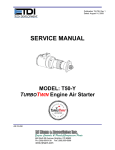
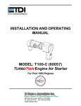
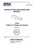
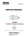
Publication T5-703, Rev. 2 Dated: July 31, 2009 SERVICE MANUAL T50-P TURBOTWIN Engine Air Starter AN 99-447 TDI TURBOTWIN FROM TECH DEVELOPMENT TABLE OF CONTENTS Section 1.0 2.0 3.0 4.0 5.0 6.0 Subject Introduction……………………………. Description of Basic Groups…………. Disassembly………………………… … Cleaning and Inspection…………… … Assembly………………………………. Parts List……………………………. … Page 1 3 5 7 10 13 LIST OF TABLES Table No. 1 2 3 4 5 6 Title T50 Series Service Tool Kits………… Cleaning Materials & Compounds.. … Parts Inspection Check Req………. … Parts Wear Limits………………….. … Torque Values…………………………. Materials for Assembly……………….. Page 5 7 8 9 9 10 LIST OF ILLUSTRATIONS Figure 1 2 3 4 5 6 7 8 9 10 11 12 13 Title Page TDI Turbotwin Nameplate……………. 2 T50 Series Part Number Coding…….. 2 Turbine Housing Assembly…………… 3 Gearbox Housing Assembly…..……… 4 Drive Assembly………………………… 4 Bendix Drive Removal………………… 5 Turbine Rotor Removal.………………. 6 Turbine Shaft Removal……………….. 6 Nozzle 2 Removal…………………….. 6 Gear Teeth Wear Allowance…………. 9 Turbine Bearing/Shaft Removal.….. … 10 T50 Illustrated Parts List……………… 15 T50 IPB (S/N: 0610-0994 & After)……..16 Publication T5-703, Rev. 2 Issued July 31, 2009 Page: i TDI TURBOTWIN FROM SECTION 1.0 INTRODUCTION 1.1 GENERAL INFORMATION This manual provides information for servicing, disassembly, and re-assembly of the TDI Turbotwin T50-P air starter. If there are questions not answered by this manual, please contact your local TDI distributor or dealer for assistance. Illustrations and exploded views are provided to aid in disassembly and re-assembly. The TDI Turbotwin T50-P engine air starter is specially designed for starting today’s automated, low-emission engines. The Turbotwin uses aerodynamic speed control, allowing for cranking torque throughout the start cycle. The Turbotwin T50-P air starter is suited to operate within a wide range of inlet pressures and ambient temperatures. This starter is designed for operation on compressed air and natural gas. The robust turbine motor design in the Turbotwin T50-P air starter has no rubbing parts and, therefore, is tolerant of hard and liquid contamination in the supply to the starter. As with all TDI air starter products, there are no rubbing parts so there is no lubrication required. This eliminates failures due to lubricator problems, the expense of installing and maintaining the system, and the messy and hazardous oil film around the starter exhaust. The starter is factory grease packed for the life of the starter so it requires no maintenance. Please review the rest of this manual before attempting to service the TDI Turbotwin T50-P air starter. 1.2 WARNINGS, CAUTIONS, & NOTES Throughout this manual, certain types of information will be highlighted for your attention: WARNING - used where injury to personnel or damage to equipment is possible. CAUTION - used where there is the possibility of damage to equipment. Publication: T5-703, Rev. 2 Issued: July 31, 2009 TECH DEVELOPMENT NOTE - use to point out special interest information. 1.3 DESCRIPTION OF OPERATION The Turbotwin T50-P air starter is powered by a two stage axial flow turbine coupled to a simple planetary gear reduction set. The T50-P air starter incorporates a pre-engaged drive coupled to the starter gearbox drive train to provide a means of disengaging the pinion from the engine’s ring gear. The high horsepower of the turbine air motor combined with the planetary gear speed reducer results in a very efficient and compact unit. The Turbotwin T50-P air starters can be used over a wide range of drive pressures from 40 psig (2.7 BAR) to 120 psig (8 BAR) and are suitable for operation on compressed air and natural gas. The T50-P weighs approximately 34 pounds (15 KG) and is capable of delivering over 45 HP (33.6 kW) of cranking power at the maximum pressure of 120 psig (8 BAR). 1.4 INSTALLATION AND SERVICE It is important to properly install and operate the TDI T50-P air starter to receive the full benefits of the turbine drive advantages. It must be installed in accordance with the instructions provided by Tech Development (TDI). WARNING Failure to properly install the starter or failure to operate it according to instructions provided by TDI may result in damage to the starter or engine, or cause personal injury. DO NOT OPERATE THIS STARTER UNLESS IT IS PROPERLY ATTACHED TO AN ENGINE. Repair technicians or service organizations without turbine starter experience should not attempt to repair this starter until they receive factory approved training from TDI, or its representatives. Proper operation and repair of your TDI Turbotwin will assure continuous reliability and superior performance for many years. Page 1 TDI TURBOTWIN FROM TECH DEVELOPMENT 1.5 NAMEPLATE INFORMATION The nameplate located on the turbine housing provides important information regarding the construction of your T50-P air starter, refer to Figure 1. The part number coding explanation, refer to Figure 2, can help you when talking to your distributor. TURBOTWIN PNUEMATIC STARTER TECH DEVELOPMENT INC. 6800 POE AVE.,DAYTON OH MODEL NO. SERIAL NO. T510 9910-112 CW(RH) (CCW)LH) X . PART NUMBER NOTE You should always have the starter’s Part Number, Serial Number, Operating Pressure, and Direction of Rotation information before calling your TDI distributor or dealer. T510-60048-01R-4 . HOUSING PROOF PRESSURE IS 600 PSIG MAX OPERATING INLET PRESS. 120 WARNING PSIG DO NOT OPERATE UNLOADED, WITHOUT EXHAST GUARD OR WITHOUT EXHAUST FITTING Figure 1. TDI TURBOTWIN Nameplate T5 10 - 60048 - 01R - 0 - 00 MODEL T50 PRODUCT ORIENTATION OF INLET/CONTROL PORTS 00= 0 DEGREES (STD) 01= 30 DEGREES 02= 60 DEGREES 03= 90 DEGREES 04= 120 DEGREES 05= 150 DEGREES 06= 180 DEGREES NUMBER OF NOZZLES 08= 8 NOZZLES 10= 10 NOZZLES 14= 14 NOZZLES DRAWING NUMBER FOR T50 MODEL TYPE 60048= T50P (PRE-ENGAGED, OUTBOARD NOSE, 11.2:1 RATIO, SAE 3 MOUNT) 60051= T50Y (PRE-ENGAGED, OVERHUNG PINION, 11.2:1 RATIO, SAE 3 MOUNT) 60052= T50Y (PRE-ENGAGED, OVERHUNG PINION, 11.2:1 RATIO, SAE 1 MOUNT) PINION CODES 07= 210 DEGREES 08= 240 DEGREES 09= 270 DEGREES 10= 300 DEGREES 11= 330 DEGREES EXHAUST OPTIONS 0= EXHAUST SCREEN 1= (NOT AVAILABLE) 2= 2" NPT STRAIGHT 3= (NOT AVAILABLE) 4= EXHAUST CLOSURE PLATE (ECP) 5= (NOT AVAILABLE) 6= (NOT AVAILABLE) 7= (NOT AVAILABLE) 8= (NOT AVAILABLE) 01= 6/8 DP, 11T ON 12T BLANK, 2.00 PD, 20° PA 02= 8/10 DP, 12T ON 13T BLANK, 1.625 PD, 20° PA 03= 8/10P, 10T ON 11T BLANK, 1.375 PD, 20° PA 04= 3 MOD, 9T ON 9.567T BLANK, 1.063 PD, 14.5° PA 05= 3 MOD, 11T ON 11.7 BLANK, 1.299 PD, 14.5° PA 06= 3.5 MOD, 11T ON 11.64T BLANK, 1.516 PD, 14.5° PA 07= 3.5 MOD, 13T ON 13.7T BLANK, 1.791 PD, 14.5° PA 08= 8/10P, 13T ON 14T BLANK, 1.750 PD, 20° PA 09= 3.5 MOD, 15T ON 15.66T BLANK, 1.772 PD, 14.5° PA ROTATION 10= USE CODE #03 (THIS IS A LH VERSION) R= RH (CW) 11= 3.5 MOD, 17T ON 17.67T BLANK, 2.343 PD, 14.5° PA L= LH (CCW) 12= USE CODE #02 (THIS IS A LH VERSION) 13= 3.5 MOD, 14T ON 14.7T BLANK, 1.929 PD, 14.5° PA 14= 8/10DP, 12T ON 12T BLANK, 1.500 PD, 20° PA 15= 4.25 MOD, 11T ON 11T BLANK, 1.840 PD, 20° PA 16= 6/8DP, 12T ON 12.7T BLANK, 2.126 PD, 20° PA 17= USE CODE #01 (THIS IS A LH VERSION) 18= USE CODE #07 (THIS IS A LH VERSION) 19= 8/10 DP, 12T ON 13T BLANK, 1.625 PD, 20° PA 20= 3.5 MOD, 14T ON 14.7T BLANK, 2.026 PD, 20° PA 21= 4 MOD, 15T ON 15.65T BLANK, 2.465 PD, 0.325 CORRECTION FACTOR, 14.5° PA 22= 3.5 MOD, 14T ON 14.68T BLANK, 2.023 PD, 0.34 CORRECTION FACTOR, 14.5° PA 23= 3.5 MOD, 14T, 2.023 PD, 0.34 CORRECTION FACTOR, 20° PA Figure 2. T50 Series Nameplate Identification Page 2 Publication T5-703, Rev. 2 Issued: July 31, 2009 TDI TURBOTWIN FROM SECTION 2.0 DESCRIPTION OF BASIC GROUPS 2.1 GENERAL The TDI Turbotwin T50-P air starter is a lightweight, compact unit driven by a two stage turbine air motor. The starter is composed of three basic assembly groups: Turbine Housing Assembly, Gearbox Housing Assembly, and Bendix Drive Assembly. TECH DEVELOPMENT 2.2 TURBINE HOUSING ASSEMBLY The Turbine housing assembly, refer to figure 3, consists of a stage one (23) and a stage two (13) turbine rotor mounted on sungear shaft (29). The front bearing (15) is secured by a retainer plate (27) and the aft bearing is pre-load by a spring washer (16). The ring gear (31) is installed between the turbine assembly (26) and the gearbox housing (41) and secured by four screws (42). Figure 3. Turbine Housing Assembly Publication: T5-703, Rev. 2 Issued: July 31, 2009 Page 3 TDI TURBOTWIN FROM 2.3 GEARBOX HOUSING ASSEMBLY The gearbox housing assembly, refer to figure 4, consists of a planet gear carrier and output shaft (32), three planet gears (36), needle bearings (37), spacers (35), and planet shafts (34). TECH DEVELOPMENT The carrier shaft (32) is mounted on a single bearing (38) in the gearbox housing (41). The retainer ring (48) secures the carrier shaft in the gearbox housing. The bearing housing (44) and pre-engaged piston (50) are installed in the gearbox housing (31). Figure 4. Gearbox Housing Assembly 2.4 DRIVE ASSEMBLY The drive assembly, refer to figure 5, consists of a preengagement drive (53) and drive housing (56). Twelve screws (57) secure the drive housing to the gearbox housing. The front end of the carrier shaft (32) is mounted in a needle bearing (58), which is installed in the nose of the drive housing. Split rings (52) and a return spring (54) aid in the disengagement of the pinion from the engine’s ring gear. Figure 5. Drive Assembly Page 4 Publication T5-703, Rev. 2 Issued: July 31, 2009 TDI TURBOTWIN FROM TECH DEVELOPMENT SECTION 3.0 DISASSEMBLY 3.3 GEARBOX HOUSING 3.1 GENERAL Always mark adjacent parts on the starter; Nozzle 2/ Containment Ring (21), Turbine Housing (26), Gearbox Housing (41), and Drive Housing (56) so these parts can be located in the same relative position when the starter is reassembled. 3.3.1 Removal of Gearbox Housing Remove the four screws (42) and separate the gearbox assembly from the turbine assembly. If the gearbox is too tight, tap it with a mallet to loosen. 3.3.2 Gearbox Disassembly Do not disassemble the starter any further than necessary to replace a worn or damaged part Remove snap ring (48) and two thrust washers (47) from carrier shaft (32). Always have a complete overhaul kit on hand before starting any overall of a Turbotwin T50-Pair starter. Never use old screws, seals, and o-rings. Apply pressure to the carrier shaft to remove it from the gearbox housing. The tools listed in Table 1 are suggested for use by technicians servicing the Turbotwin T50-P air starter. The best results can be expected when these tools are used. TOOL DESCRIPTION Spanner Wrench Stage 2 Rotor Puller Tool Tool, Turbine Bearing Tool, Bearing/Seal Tool, Seal Positioning TDI/PN 2-27272 52-20076 45-25294 2-26943 45-25316 Table 1. T50 Series Service Tools (P/N: T50-28570) 3.2 DRIVE HOUSING 3.2.1 Removal of Drive Housing Remove four screws (39) and press the bearing housing/pre-engaged piston assembly (44,50) from the gearbox housing. Hand press bearing housing (44) out of pre-engaged piston (50). 3.3.3 Carrier Shaft/Planet Gear Disassembly Remove snap ring (33) from planet shaft (34) and push shaft through holes in assembly. Refer to figure 6. Slide the planet gear (36) out from the carrier shaft and remove the two spacers (35). Press the needle bearing (37) from the planet gear (36) to remove it. Mark position of drive pinion opening relative to gearbox housing for reference during re-assembly. Remove the 12 screws (57) and pull drive housing (56) from gearbox housing (41). If drive housing is too tight, tap it with a mallet to loosen. 3.2.2 Removal of Drive Remove return spring (54) and pull drive (53) from carrier shaft assembly (32). Remove split rings (52) from drive assembly. 3.2.3 Drive Bearing Removal CARRIER SHAFT ASSEMBLY (32) PLANET GEAR (36) PLANET GEAR SPACER (35) PLANET BEARING (37) PLANET SHAFT (34) RETAINING RING (33) Press needle bearing (58) from drive housing (56) using press tool. Publication T5-703, Rev. 2 Issued: July 31, 2009 Figure 6. Carrier Shaft Disassembly Page 5 TDI TURBOTWIN FROM TECH DEVELOPMENT Remove the aft bearing (15), wavy washers (16), and labyrinth (17) from nozzle 2. 3.4 TURBINE HOUSING 3.4.1 Stage 2 Rotor Removal Remove four screws (4), ECP assembly (5), exhaust support (9), and exhaust guard (10). Units with an exhaust screen (no ECP) will utilize 8 screws. Hold the stage 2 rotor (13) and remove the turbine screw (11) and washer (12). NOTE Secure the sun gear (29) in a soft jaw vise when removing turbine screw. Install three screws (42) removed from the gearbox housing into the jack holes on the turbine housing (26) as shown in figure 9. Turn the screws in sequence until the turbine housing (26) is completely removed from the nozzle 2 (21). Remove the stage 1 rotor (23) and square key (14). Press turbine shaft (29) through forward bearing (15) to remove bearing from shaft. ARBOR PRESS PRESSING TOOL Install rotor puller tool P/N 52-20076 and remove the stage 2 rotor as shown in figure 7. ROTOR, STG 1 (23) SQUARE KEY (14) PULLER TOOL 52-20076 ROTOR 2 (13) TURBINE SHAFT (29) NOZZLE, STAGE 1 (26) NOZZLE 2/CONTAINMENT RING (21) Figure 8. Turbine Shaft Removal NOZZLE, STAGE 1 (26) 1/4 - 20 UNC SCREW Figure 7. Turbine Rotor Removal Remove the square key (14)) from turbine shaft (29). 3.4.2 Turbine Housing Disassembly Place the turbine on a firm surface with the sun gear end facing up. Remove three screws (28) and bearing retainer plate (27) from turbine housing (26). Units with S/N: 06100994 and after will utilize four screws. NOZZLE 2/CONTAINMENT RING (21) Figure 9. Nozzle 2 Removal With the exhaust end facing up, press turbine shaft (29) through turbine housing (26) as shown in figure 8. Remove labyrinth (24) from turbine shaft. Page 6 Publication T5-703, Rev. 2 Issued: July 31, 2009 TDI TURBOTWIN FROM TECH DEVELOPMENT SECTION 4.0 CLEANING and INSPECTION Clean aluminum parts using the solutions per Table 2; soak for 5 minutes. Remove parts, rinse in hot water, and dry thoroughly. 4.1 CLEANING Clean corroded steel parts with a commercially approved stripper. Degrease all metal parts, except bearings, using a commercially approved solvent. Refer to Table 2. NOTE Never wash bendix assembly or bearings in cleaning solvents. It is recommended bearings be replaced with new parts. Clean corroded aluminum parts by cleaning as stated above and then immerse the parts in chromic-nitricphosphoric acid pickle solution per Table 2. Rinse in hot water and dry thoroughly. MATERIAL or COMPOUND Degreasing Solvent (Trichloroethylene) (O-T-634) Acetone Aluminum Cleaning Solution MANUFACTURER Commercially Available Commercially Available Diversey Corp., 212 W. Monroe, Chicago, IL 60606 Dissolve 5 oz of Diversey 808 per gallon of water at 155- 165F. Steel Cleaner - Rust & Corrosion Oakite Products Corp., 50 Valley Rd., Berkeley Heights, NJ 07992 Mix 3-5 lb. of Oakite rust Stripper per gallon of water; use at 160- 180F. Chromic-Nitric-Phosphoric Acid Pickle Solution Mix 8lb. of chromic acid, 1.9 gal. of phosphoric acid, 1.5 gal. of nitric acid with enough water to make a total of 10 gal. of solution. WARNING Follow all instructions provided with the MSDS sheets on the materials and compounds listed above. Table 2. Cleaning Materials and Compounds 4.2 INSPECTION Use Table 3 as a guide to check for acceptable condition of the parts listed. Check all threaded parts for galled, crossed stripped, or broken threads. Check all parts for cracks, corrosion, distortion, scoring, or general damage. Publication T5-703, Rev. 2 Issued: July 31, 2009 Check all bearing bores for wear. Check gear teeth and turbine housing ring gear for wear. In general, visually check for spalling, fretting, surface flaking, chipping, splitting, and corrosion. If wear is apparent, check the gear teeth dimensions in accordance with Table 4. Nicks and dents that cannot be felt with a .020 inch radius scribe are acceptable. Page 7 TDI TURBOTWIN FROM Part Description Drive Drive Housing Planet Gear Check For Worn loose or missing parts Cracks and breakage Cracked, chipped, worn, or galled teeth. Carrier Shaft Cracks, scoring or raised metal in planet shaft holes and keyways. Integrity of knurl/keyed connection. Planet Pins Wear grooves or flat spots Washers Gearbox Housing Sungear/Turbine Shaft Wear grooves Cracks and Breakage Cracks, scoring, wear grooves, chipped or broken gear- teeth, galling or scoring on bearing surface of shaft. Raised metal on the keyway. Parallelism of end surfaces Cracks and breakage Spacers Turbine Housing Ring Gear Needle Bearings Ball bearings Containment Ring/ Nozzle Turbine Rotors Cracks, worn, chipped, or broken gear teeth. Freedom of needle rollers Freedom of rotation without excessive play between races Corrosion, erosion, cracks and broken nozzle edges. Corrosion, erosion, and broken edges. cracks TECH DEVELOPMENT Requirements (Defective Parts Must Be Replaced) Defective unit to be replaced. Use figure 10 as a guideline for acceptable pinion wear. Cracks are not acceptable Wear must not exceed limits per table 4. There shall be no evidence of excessive wear. Deformation of metal (smearing) in planet pin holes & keyways not acceptable. Scoring on bearing diameter not to exceed .005 depth. Wear must not exceed limits per Table 4. Wear grooves in flat spots not permitted. Wear must not exceed limits per Table 4. Wear must not exceed limits per Table 4. Cracks and breakage not acceptable. Wear must not exceed limits per Table 4. Ends must be parallel within 0.0005. Cracks and breakage are not acceptable. Minor surface damage is permitted if function is not impaired. Wear must not exceed limits per Table 4. Replace bearings Replace bearings Cracks and breakage are not acceptable. Minor surface damage is permitted if function is not impaired. Minor tip rub is permitted if function is not impaired. Bore and key way wear Wear is not permitted. Table 3. Parts Inspection Check Requirements Page 8 Publication T5-703, Rev. 2 Issued: July 31, 2009 TDI TURBOTWIN FROM PART DESCRIPTION Ring gear / Turbine Housing Internal measurement between two .072 diameter pins. Sun Gear / Turbine Shaft Bearing diameter External measurement over two .072 diameter pins. 11.2:1 TECH DEVELOPMENT LIMIT, Inches 4.6655 max. .5566 min Planet Gear External measurement over two .085 diameter pins. Figure 10. Gear Teeth Wear Allowances 2.2217 min 11.2:1 Table 4. Parts Wear Limits ITEM NUMBER * TORQUE In-lbs Nm 4 (Screw) 190 21 11 (Screw) 220 25 18 (Screw) 75 8 28 (Screw) 113 13 39 (Screw) 81 9 42 (Screw) 190 21 57 (Screw) 190 21 * Refer to section 6 for part number identification. Table 5. Torque Values Publication T5-703, Rev. 2 Issued: July 31, 2009 Page 9 TDI TURBOTWIN FROM TECH DEVELOPMENT SECTION 5.0 ASSEMBLY 5.1 GENERAL INFORMATION ARBOR PRESS PRESSING TOOL 2-26943 The tools listed in Table 1 are suggested for use by technicians servicing the Turbotwin T50-P air starter. The best results can be expected when these tools are used. CAUTION Replace all screws, o-rings, lip seals, and bearings. These parts are included in the overhaul kit shown in the Parts List, Section 6.0. NOTE Always press the inner race of a ball bearing when installing a bearing onto a shaft. Always press the outer race of a ball bearing when installing into a housing. DO NOT LOAD BEARING BALLS. Figure 11. Turbine Bearing / Shaft Installation 5.2.2 Lubricate all o-rings with petroleum jelly or Parker Oring Lube before assembly. Refer to Table 5 for a list of materials to be used during assembly. MATERIALS SOURCE Petroleum Jelly Commercially Available Parker-O-Ring Lube Commercially Available Aeroshell #6 Grease Commercially Available Loctite RC290 Commercially Available Grease, gearbox TDI P/N 9-94121-001 Table 6. Materials for Assembly 5.2 TURBINE HOUSING Turn the turbine nozzle over (exhaust end up) and install the labyrinth (18) onto the shaft. For units with 0610-0994 and after press lip seal P/N: 2-26179 onto spacer P/N: 9-93114 and press lip seal with lips facing up into aft end of nozzle 1. Press the square key (14) into the keyway of turbine shaft (29) until seated. Install stage 1 rotor (23) by sliding over turbine shaft (29), while simultaneously aligning the key with the keyway in the rotor. 5.2.3 5.2.1 ROTOR 1 INSTALLATION STAGE 2 NOZLE INSTALLATION TURBINE BEARING INSTALLATION Press the turbine bearing (15) onto the turbine shaft (29) until seated. Press the turbine bearing/shaft assembly (15,29) into the turbine housing (26). Use press tool P/N 2-26943 if required per figure 11. Do not press on the end of the shaft because the load could damage the bearing balls. Install the bearing retainer (27) into the turbine housing (26) and secure with three screws (28) Torque to 75 in-lbs. Units with S/N: 0610-0994 and after will utilize four screws. Install o-ring (25) onto turbine housing (20). Install turbine housing (26) into nozzle 2 containment housing (21). NOTE The air inlet port on nozzle 2 must be aligned with the casting indentation on the turbine housing. 5.2.4 ROTOR 2 INSTALLATION Turn the turbine nozzle over (exhaust end up) and install the labyrinth (17) onto the shaft. Install pre-load springs (16) into bearing bore of nozzle 2 containment housing (21). Page 10 Publication T5-703, Rev. 2 Issued: July 31, 2009 TDI TURBOTWIN FROM TECH DEVELOPMENT Install o-ring (43) into the groove on the bearing housing (44). Apply a light coating of oil to the bearing bore in the Nozzle Containment Assembly and press the turbine bearing (15) over the turbine shaft and into the bearing bore using press tool P/N. 2-26943 Insert key (14) into turbine shaft keyway and install stage 2 rotor (13) onto shaft while simultaneously aligning the key with the keyway in the rotor. NOTE Apply a small amount of Aeroshell grease to the outer wall of the bearing hub and the inside wall of the gearbox housing to allow for easier housing installation. Secure stage 2 rotor with rotor washer (12) and rotor screw (11). Torque to 220 in-lb. Install the bearing housing assembly (38,44,46) in the forward side of the gearbox housing (41) and secure with four screws (39). Torque to 81 In-Lbs. Turn turbine housing over and install o-ring (30) into the o-ring groove on the turbine housing (26). Install two o-rings (49,51) into the grooves on the preengaged piston (50). Install plug (22) into Nozzle Containment Assembly. Install the ring gear (31) onto turbine housing with the dowel pin hole facing up. Install dowel pin (40) into dowel pin hole in ring rear (31). 5.3 GEAR BOX ASSEMBLY 5.3.1 PLANETARY GEAR CARRIER ASSEMBLY Press needle bearings (37) into planet gears (36) using arbor press. The bearing ID stamping must be against pressing tool. The bearing should be centered between gear faces. NOTE Apply a small amount of Aeroshell # 6 grease to the inner and inner walls of the pre-engaged piston to allow for easier installation. Press pre-engaged piston into the forward side of the gearbox housing and remove any excess grease from gearbox housing. Install lip seal tool PN: 45-25316 into forward side of gearbox housing (41) placing tapered end of tool into lip seal (46). Install gearbox housing onto carrier shaft and place two thrust washers (47) on carrier shaft (32). Secure with snap ring (48) using snap ring pliers. Place thrust washer (35) on each side of planet gear (36) and install into carrier shaft (32) slot. 5.3.3 Install planet shaft (34) into the carrier and secure with snap ring (33). Be sure the anti-rotation pin is inserted into the slot on the carrier shaft. Apply a small amount of Aeroshell # 6 grease to split rings (52) and install split rings onto drive assembly (53). 5.3.2 Install o-ring (55) onto drive housing (56) CARRIER SHAFT INSTALLATION DRIVE INSTALLATION Install o-ring (43) into forward side of gearbox housing (41). Install the drive assembly (53) onto carrier shaft and place return spring (54) over drive assembly. If removed, press gearbox bushing (38) into bearing housing (44). 5.3.4 Press the lip seal (46) into the forward side of the bearing housing (44) until seated using press tool P/N: 2-26943. Publication T5-703, Rev. 2 Issued: July 31, 2009 NOSE BEARING INSTALLATION Place the drive housing onto arbor press with the nose of drive facing down. Press needle bearing (58) into drive housing (56) using arbor press. The bearing ID stamping must be against pressing tool. Do not press bearing tight against the Page 11 TDI TURBOTWIN FROM TECH DEVELOPMENT drive housing shoulder. In addition, be sure stamped end is beneath shoulder of bearing bore. Align gearbox assembly with turbine assembly and fasten together with four screws (42). 5.4 FINAL ASSEMBLY Apply o-ring grease to gearbox housing. o-ring (30) and install onto Apply liberal amounts of grease (100 grams) to planet gears (36), turbine shaft sun gear (29) and ring gear (31). Install drive housing (56) onto gearbox housing (41) and secure with twelve screws (57). Torque to 150 inlb. Install exhaust closure plate assembly using four screws (4). Torque to 150 in-lb. Temporarily install one screw (42) into ring gear (31) to prevent it from rotating while applying grease. Page 12 Publication T5-703, Rev. 2 Issued: July 31, 2009 TDI TURBOTWIN FROM TECH DEVELOPMENT SECTION 6.0 PARTS LIST The components illustrated and/or described in this section are for the Turbotwin T50-P air starter. When rebuilding a T50-P air starter, it is recommended to purchase and completely install the appropriate service kit(s). T50-P ILLUSTRATED PARTS LIST ITEM # 1 2 3 4 5 6 7 8 9 10 11 12 13 14 15 16 17 18 19 20 21 21 22 23 24 25 26 26 26 26 27 28 29 30 DESCRIPTION Nut, Hex Washer, Flat Plate, Baffle Screw Housing, Exhaust Cover Bushing Spring, Compression Post Exhaust Support Exhaust Guard Screw, Rotor Attachment Rotor Washer Stage 2 Rotor Square Key (1/8") Turbine Bearing Bearing Pre-Load Spring Spacer / Labyrinth Screw Inlet Flange O-Ring Containment, Nozzle 2, RH Containment, Nozzle 2, LH Hollow Hex Plug Stage 1 Rotor Spacer/Labyrinth O-Ring Turbine Hsg. / Stage 1 (10 Noz. RH) Turbine Hsg. / Stage 1 (10 Noz. LH) Turbine Hsg. / Stage 1 (14 Noz. RH) Turbine Hsg. / Stage 1 (14 Noz. LH) Bearing Retainer Screw Turbine Shaft 11.2:1) O-Ring Publication T5-703, Rev. 2 Issued: July 31, 2009 PART NUMBER QTY. 9-92155-06 1 9-93018-011 2 2-20192 1 14F-25020-014 8 2-28369 1 9-91436 1 9-90408-016 1 2-27223 1 2-27475 1 2-28380 1 14F-25028-012 1 9-93047 1 2-28410 1 9-90220-050 2 9-91224 2 9-90439 2 2-28445 1 71F-31218-020 4 2-28360 1 9-90001-031 1 2-28359-00R 1 2-28359-00L 1 9-93501-002 1 2-27225 1 2-28444 1 9-90001-047 1 2-28354-10R 1 2-28354-10L 1 2-28354-14R 1 2-28354-14L 1 2-28446 1 71F-25020-012 3 2-28339 1 9-90001-047 2 Overhaul Kit T50P-28533-001 Page 13 TDI TURBOTWIN FROM ITEM # 31 32 33 34 35 36 37 38 39 40 41 42 43 44 45 46 47 48 49 50 51 52 53 53 53 53 53 54 55 56 57 58 DESCRIPTION Ring Gear Carrier Shaft Assembly Retaining Ring Planet Shaft Planet Gear Spacer Planet Gear (11.2:1) Planet Bearing Bushing Screw Dowel Pin Gearbox Housing Screw O-Ring Bearing Housing O-Ring Lip Seal Thrust Washers Retaining Ring O-Ring Pre-engage Piston O-Ring Split Rings Drive, 6/8P, 11T, RH Drive, 6/8P, 11T, LH Drive, 3.5MOD, 14T, RH Drive, 3.5MOD, 14T, LH Drive, 6/8P, 12T, RH Return Spring O-Ring Drive Housing (6/8P) Screw Nose Bearing (6/8P) PART NUMBER 2-28430 2-28358 9-92001-001 2P-20182 9-93004 2-28316 9-91004-001 9-91405 14F-19024-012 9-91502-007-0-10 2-28352 14F-25020-044 9-90001-035 2-24114 9-90002-331 2-23810 9-93085 9-92001-025 9-90002-336 2-24644-001 9-90002-234 2-23419 2-22954 2-22956 2-26816 2-25933 2-26143-001 9-90422 9-90001-041 2-24127-007 14F-25020-012 9-91408 TECH DEVELOPMENT QTY. 1 1 3 3 6 3 3 1 4 1 1 4 1 1 1 1 2 1 1 1 1 2 1 1 1 1 1 1 1 1 12 1 Overhaul Kit T50P-28533-001 Page 14 Publication T5-703, Rev. 2 Issued: July 31, 2009 TDI TURBOTWIN FROM TECH DEVELOPMENT Figure 12. T50-P Illustrated Parts List Publication T5-703, Rev. 2 Issued: July 31, 2009 Page 15 TDI TURBOTWIN FROM TECH DEVELOPMENT T50-P TURBINE ASSEMBLY (effective serial #: 0610-0994) ITEM # 24 24A 26 26 26 26 26 26 27 28 DESCRIPTION Bearing Spacer Lip Seal Turbine Hsg. / Stage 1 (8 Noz. RH) Turbine Hsg. / Stage 1 (8 Noz. LH) Turbine Hsg. / Stage 1 (10 Noz. RH) Turbine Hsg. / Stage 1 (10 Noz. LH) Turbine Hsg. / Stage 1 (14 Noz. RH) Turbine Hsg. / Stage 1 (14 Noz. LH) Bearing Retainer Screw Overhaul Kit PART NUMBER QTY T50P-28533-001 √ 9-93114 1 √ 2-26719 1 2-28354-08R 1 2-28354-08L 1 2-28354-10R 1 2-28354-10L 1 2-28354-14R 1 2-28354-14L 1 2-27406 1 71F-25020-012 4 √ Figure 13. Model T50 Series Turbine Assembly Configured for Air & Natural Gas (Effective serial #: 0610-0994) Page 16 Publication T5-703, Rev. 2 Issued: July 31, 2009