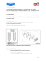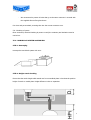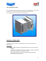
1
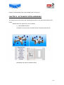
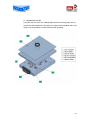
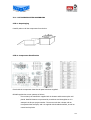
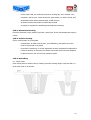
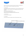
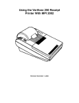
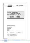
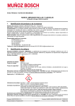
USER MANUAL
w w w . o r y m o . c o m
Avda. del Cid, 6 -Polígono Industrial Torrubero
46136 Museros-VALENCIA-Spain
Tel. +34 96 145 20 17
e-mail: [email protected]
www.orymo.com
TABLE OF CONTENTS
CHAPTER I: ADVANCE...........................................................................................................
CHAPTER II INTRODUCTION.................................................................................................
CHAPTER III: SAFETY............................................................................................................
III.1.- Worker safety........................................................................................................
III.2.- Electric precautions................................................................................................
III.3.- Mould....................................................................................................................
III.4.- Injection machine..................................................................................................
CHAPTER IV: HOT RUNNER SYSTEM ASSEMBLING.................................................................
IV.1.- Hot runner system assembling................................................................................
IV.2.- Monoblock system assembling.................................................................................
CHAPTER V: SYSTEM START..................................................................................................
V.1.- Mould assembling on injection machine.....................................................................
V.2.- Start.......................................................................................................................
CHAPTER VI: POTENTIAL FAULTS.........................................................................................
VI.1.- Flow signs.............................................................................................................
VI.2.- Brown or silver streaks (Burn)................................................................................
VI.3.- Humidity flashing..................................................................................................
VI.4.- Bad superficial extructure/texture...........................................................................
VI.5.- Short shot.............................................................................................................
VI.6.- Deflashing............................................................................................................
VI.7.- Sink marks............................................................................................................
VI.8.- Drooling...............................................................................................................
VI.9.- Lakes...................................................................................................................
VI.10.- Warpage.............................................................................................................
CHAPTER VII: GENERAL INFORMATION AND RECOMENDATIONS.............................................
VII.1.- Colour changes....................................................................................................
VII.2.- Purge of injection unit..........................................................................................
VII.3.- Plastic cleaning....................................................................................................
VII.4.- Use of recycled material.......................................................................................
10-1
CHAPTER I: AVANCE
We take the advantage of thanking your confidence on our products.
The main aim of this assembling manual is to assist users on the assembling and working
process of the ORYMO Hot Runner Systems.
In case of additional information, please contact your agent or ORYMO´s headoffice
_____________________________________________________________
The staff safety responsibility falls on owner/user of the product exclusively. The correct
instruction and personnel training on dangerous duties is his obligation, including the
maintenance and the correct use of safety measures. It must be provided the necessary
protecting clothes, special gloves including face protector. None operating instruction of
products supplied by ORYMO avoid user to fulfil his obligations and taking precautions. In case
of accident, ORYMO avoids any responsibility due to incorrect handling.
_____________________________________________________________
This publication can not be transmited nor reproduced on any cataloque weather electronic
system or mechanic including photocopier, recording machines or any data base without the
autorization of the publisher. All specifications can be changed without prior notice.
CHAPTER II: INTRODUCTION
The Hot Runner System aim is to distribute warm plastic from the inyection unit to all inyection
points of the mould, keeping constant temperature from the nozzle machine. Plastic goes
through nozzle machine to hot runner system nozzle, gets into manifold and it is distributed to
all nozzles. All channels which plastic goes through are balanced, providing flow controlled and
even dropping presure along all points.
The system is heated from exterior to provide a proper flow without restrictions in melted
plastic runners. The heaters are placed on access nozzle, manifold and diferent nozzles. For
nozzles and sprue, the heater is threaded in order to ahcieve an even heat distribution. For
manifold, the heater is placed in slot placed on either sides of the manifold. All heaters can be
replaced in case of damage or scorching. To control temperature on all areas, a independent
thermocouple goes with each nozzle ( except on sprues, which it is incorporated) resistence.
10-2
CHAPTER III: SAFETY
Injection moulds work with high pressures and temperature. As consequence, all security
devices must be properly assembled on mold and machine to operate accurately. Do not
disassemble these devices.
III.1.- WORKER SAFETY
Security shoes, protection glasses and special gloves are highly recommended. Workers must
be warmed against gas emissions and lakes (overheated plastic can provoke dangerous gases
suddenly by the time to dismantle an injection point)
close to mould (hot runner nozzle) or
injection unit (machine nozzle, chute). A mirror is needed to look at hopper, nozzle machine
and injection points never without protection. Storing areas for row material must be indicated,
easy access is necessary for maintenance.
III.2.- ELECTRIC PRECAUTIONS
Electric wires and hoses must be checked ofently and replaced in case of wear. Switch off
power supply and then the wires. Do not mix the thermocouple wires with the power suppply
ones. High voltage wires are connected to the mould. Thermocouple wires are not design to
supply electricity so they can not hold overcurrent, electric supply wires will provide mistaken
temperature results.
Pipe water can be very close to mould electric connection so water loosing can start shor
circuits. Loosing of hydraulic fluid can provoke fire. To avoid it, pipes, hoses and hydraulic
accessories must follow a maintenance program.
III.3.- MOULD
Maintenance operations must be done after reading carefully the manufacturer machine
instructions.
The mould hoses and hydraulic flow must not obstruct with mobile pieces of the mould,
machine or robot. Furthermore, they must be long enough to avoid strain as opening mould
operations.
Hydraulic and pneumatic connections must be verify ofently to prevent possible leaks, due to
the material carried through hoses/pipes, staff must switch machine off and and release
pressure before to adjust , replace or remove these pipes.
III.4.-INJECTION MACHINE
To prevent possible accidents, the area around the machine must be keep clean of water, oil
and plastic. The cleaning always as the machine is not working.
Security instructions about purge and chute given by the manufacturer must be followed
carefully.
10-3
Purged or drooled plastic must not be handled until it is fully cool.
CHAPTER IV: HOT RUNNER SYSTEM ASSEMBLING.
This chapter has as aim showing the assembling instructions of the hot runner system in the
mould.
ORYMO offers two types of hot runner systems:
1) HOT RUNNER SYSTEM
Composed of an acces nozle, manifold, electric conexions and nozle set.
Assembling instructions are detailed below.
10-4
2) MONOBLOCK SYSTEM
It includes the hot runner set, manifold plate and the top clamp plate, with its
accessories and mechanized. This systems is suplied fully assembled and wired,
ready to be incorporated to cavity plate and start operating.
10-5
IV.1.- HOT RUNNER SYSTEM ASSEMBLING
STEP 1: Unpackaging
Carefully take out all the components from the box.
STEP 2: Components identification
Check with the components sheet that all parts have been supplied.
ORYMO supplies hot runner systems as follows:
-
On one hand, the manifold is supplied with its heaters and thermocouples well
placed. Manifold heaters are protected by a stainless steel sheet/plate on it is
stamped the Orymo project number. The acces nozzle has a heater with an
incorporated thermocouple, and it is supplied with threaded manifold, as well as
central and top limits
10-6
-
On the other hand, the remaining accesories: blockage pin, 400º resistant wire,
connectors, silicon cover, nozzle acces bush, spare heater, Cu disk for nozzle, and
assembled nozzles (heater,thermocouple, needle and pin)
-
All heaters and thermocouples are electrically checked.
-
Drawings are supplied for assembling and components checking.
STEP 3: Dimensional checking
Check the dimension of the manifold, top limits, central limit. Check with drawing that height is
correct.
STEP 4: Position checking
Check nozzle position on mould plate:
-
Head position: all edge must be clean, none deflashing, and position wire slots
must be big enough to be placed.
-
Pin position: Positioning for nozzle adjustment must be mechanized as indicated on
customer drawing. An excessive pin contact with mould would cause hot disipation
by pipe conductor, then an incorrect operation system
STEP 5: Assembling
5.1.- Nozzle insert
Clean nozzle position. Nozzle insert by checking customer drawing height. Verify that side 1 is
at the same level for all nozzles:
10-7
Nozzles must be centred on its position, with the utmost care taken not to damage them (C
type is very delicate). A Cu washer must be placed on each nozzle head.
5.2.- Nozzle wiring
Put zone number on each heater and thermocouple wire. In case of incorporated thermocouple
on nozzle heater, it will be connected but in case of independent thermocouple fault it will be
substituted.
By zones group wires through locating rings.
Guide wires through slots and take them to connectors.
Wires must not be cut off until components are in final assembly position.
5.3.- Block dowel pin
Put block dowel pin on mould plate.
5.4.- Central stop
Place central stop with its pin, checking its position with indicated height on drawing.
Blockage dowel pin
Central limit and dowel pin
10-8
5.5.- Preparing manifold
The manifold thermocouples must be protected by a silicone-fibre glass cover supplied.
Each heater terminal is joined to a ceramic terminal with 2 screws. The supplied 400º heat
resistant wire must be placed, by a terminal, screwed on the ceramic terminal heater.
5.6.- Placing manifold
Put components (manifold+ top stops + sprue) on nozzles, fixing its position by block dowel pin
and central stop. Take precautions to not trap or shear any of the nozzle wires. Check height
with customer drawing.
5.7.- Manifold wiring
Put zone number on each heater and thermocouple wire of manifold and sprue.
By zones join wires through locating rings.
Guide wires through slots and take them to connectors.
Wires must not be cut off till components are in final assembly postion.
5.8.- Total wiring of system
Make sure that the following is completed:
-
Each heater and thermocouple wire has its zone number.
-
Wires from same zone are joined.
-
All wires are carefully guided through slots to the connector plug.
10-9
-
We recommend to protect all wires that go to the same connector is covered with
the supplied silicone-fiber glass sleeve
Cut wires and put terminals, screwing then into the correct connector zone.
5.9.- Checking of system
Once connected, electrical checking by tester to verify the continuity and insulation must be
carried out.
IV.2.- MONOBLOCK SYSTEM ASSEMBLING
STEP 1: Unwraping
Unwrape the monoblock system with care:
STEP 2: Height nozzle checking
Ensure that the nozzle length which stands out from monoblock plate is less than the position
height of nozzle on mould plate. Height difference is due to expansion.
10-10
STEP 3: Mould plate assembly
Line up mould plate with monoblock system and slide them. The sliding fit has to occur without
any resistance. If not, take mould plate out and check for possible interference
Screw monoblock system onto mould plate with supplied screws.
CHAPTER V: SYSTEM START
This chapter is aimed as a guide to mould assembling on the injection machines and its
production start.
PRECAUTIONS:
-
HOT RUNNER SYSTEMS MUST BE PRESSURED AND HOT AT ALL TIME TO AVOID
PROBLMS.
-
IF WORKING WITH SENSITIVE MATERIALS (THERMAL), THE SWITCH ON MUST BE
DONE WHEN THE MATERIAL IS THERMICALLY STABLE.
-
NEVER INSERT MATERIAL INTO THE HOT RUNNER SYSTEM UNDER HIGH
PRESSURES WHEN MOULD IS OPEN.
10-11
IV.1.-MOULD ASSEMBLY ON INJECTION MACHINE
1. Mould assembly on injection machine, ensuring that flow channel diameter of
machine nozzle is approximately 1mm smaller than flow channel diameter of access
nozzle to Hot Runner Systems.
2. Connect and check water lines
3. Connect and check hydraulic/pneumatic lines.
4. Connect all electric components.
IV.2.- START
1. Switch mould cooling system on.
2. Heat injection machine oil to working temperature.
3. Heat hot runner system to correct processing temperature.
4. Expel material of hot runner system at appropriate temperature.
5. Adjust injection process conditions to part size, gate size, meterial, etc.
CHAPTER VI: POTENTIAL FAULTS
VI.1.- FLOW SIGN
There are 3 types:
-
“water” around injection point or distributed around all cavity, due to melt cools
before to mould adjustment.
-
Humidity flashing, on matt colour generally, its cause can be material humidity or
material degradation around injection point.
-
“Jetting”, due to unbalanced flow of melting.
CAUSE
REMEDY
Turbulences during
filling due to
inadequate injection
Hardening plastic
before filling cavity
Turbulences during
filling by inadequate
finding of gate
Injection machine: adjust injection flow to fill cavity slowly: reducing
speed and pressure of injection.
Injection Machine: cooling reduction till full cavity filling. Increase valve
Mould: Increase mould temperature.
Mould: Change gate location in order for material to come into contact
with a mould surface.
10-12
VI.2.- BROWN OR SILVER STREAKS(Burn)
Black stains come from plastic thermal degradation. Burn sign are brown seams that generally
came from material overheat as consequence of air traps.
CAUSE
REMEDY
Excessive melt
temperature
Injection machine: reducing valve temperature and/injection speed.
Hot runner system: reducing manifold temperature and/or of nozzles.
Check thermocouple operation.
Excessive High
temperature.
Recycled material
Too fast cavity filling
for ventilation
Inadequate ventilation
Air trap during
lamination
Material excessively
dried
Dead zones
Reduce cycle time.
Injection Machine: increase laminating time and/or use a more
powerfull machine.
Material: reduce load amount.
Reduce % of recycled material on mixture.
Injection machine: reduce time and pressure of injection, material
temperature as well.
Hot runner system: reduce temperature of manifold and nozzles.
Mould: reduce mould temeprature and increase ventilation.
Increase ventilation
Injection machine: reduce temperature of nozzle machine zone.
Reduce time and/or temperature of drying, in accordance with the
instructions of material supplier.
Injection machine: Adjust and align injection machine nozzle to sprue
of hot runner system; check that there is no material retention in all
zones.
VI.3.- HUMIDITY FLASH
Caused due to humidity on chipping or on mould surface.
CAUSE
REMEDY
Humidity on mould
surface
Humidity presence on
chipping.
Check cooling
Increase mould temperature.
Reduce time and/or temperature of drying, in accordance with the
instructions of material supplier.
Chcek handling system and material storing.
VI.4.- BAD SUPERFICIAL STRUCTURE/TEXTURE
CAUSE
REMEDY
Bad superficial mould
finishing
Bad reproduction due
to contact fault with
mould.
Air trap impedes
mould contact
Too cold material to
reproduce mould
adequately
Mould: improve mould finishing to get an appropriate shine and
texture.
Injection machine and mould: ensure good material contact with
mould by increasing injection pressure.
Mould: air cavity at air trap point (ejector pins can be used).
Injection machine: increase injection speed.
Mould: increase mould temperature.
Hot runner system: increase manifold and nozzle temeperature.
Material: use material of low viscosity if its charateristics are
appropriate.
10-13
VI.5.-UNFINISHED FILLING PIECE
Cavity is not totaly filled, in particular on the extreme flow and on the more narrow wall.
CAUSE
REMEDY
Insufficient material
Injection machine: check shot volume (insufficient dose of material)
and hole size at machine nozzle.
Hot runner system: check hot runner leaking.
Injection machine: increase injection pressure. Increase compression
time.
Correct commutation point.
Mould: increase mould temperature.
Insufficient pressure
and material in cavity
Too low mould
temperature
Low melt temperature
Gate size
Wrong opening due to
pressure retention
Injection machine: increase temperature and/or speed of injection.
Hot runner system: check if it is at appropiate temperature.
Increase manifold and nozzles temperature.
Check gate dimension
Injection machine: Increase opening pressure, opening runner and/or
opening time.
VI.6.- Flashing
It can be defined as thin material layer that flows out of cavity through mould partition line or
ejector pins position, having as result unpresentable pieces.
CAUSE
REMEDY
Damage on mould
clamping partition
surface.
Too hot mould
Insufficient clamping
pressure,overcome by
injection pressure
Overcompression of
material
Too hot melted plastic
Mould:re-mechanized clamping sides or partition edges; clean
partition lines; correct settlement of support surfaces.
Humidity on chipping
Material impurities
Mould: check heaters, thermocouples and temperature controllers.
Injection machine: increase pressure of clamping unit and reduce
injection pressure. Reduce injection speed. Change to a more powerful
injection machine (filling clamp force).
Injection machine: Reduce injection pressure.
Injection machine and Hot runner system: reduce temperature of
melted plastic. Reduce pressure and/or maintenance time. Reduce
filling speed and/or injection pressure.
Material: check and improve material storing. Increse temperature
and/or drying time, according to supplier instructions.
Check other material impurities and degraded material.
VI.7.- Sink Marks
Sink marks, both internal and external, can be defined as material lack on some piece areas
due to polymeric contraction effect .If it is external, the surface will show a clear collapse; if it is
internal,just on transparent pieces will be slightly noticed.
10-14
CAUSE
REMEDY
Insufficient pressure
on piece.
Melted plastic
excessively hot
Injection machine: Increase injection pressure.
Nerves appearance
Insufficient packing
due to worng mould
design.
Too hot injection
piece.
Premature clamping
gate due to cooling
Injection machine and Hot runner system: reduce injection, manifold
and nozzles temperature if sink marks are close to gate or thick wall
areas; Increase temperature if sink marks are far from gate or thin
wall areas.
Injection machine: increase material dose. Increase packing.
Mould: Reduce mould temperature on nerve sides.
Piece: reduce nerve part less than 80% of perpendicular section zone.
Mould: inprove design by increasing flow gate section and placing
them as closer as possible of thick piece sections.
Injection machine: reduce injection temperature
Hot runner system: reduce manifold and nozzle temperature.
Mould: reduce mould wall temperature, increase cooling.
Injection machine: increase injection speed and/or injection
temperature.
Hot runner system: Increase manifold and nozzles temperature.
Mould: Reduce cooling at gate zone; increase mould cooling
VI.8.- DROOLING AND GATE STRINGING
On injection point, the piece is not fairly broken.
CAUSE
REMEDY
Hot runner system: reduce manifold and nozzles temperature. Check
Hot excess on injection thermocouple nozzles.
point.
Mould: increase cooling at gate zone. Check nozzle deph with drawing
supplied (pin too close to injection point can provoke drooling).
Insufficient cooling
Injection machine: Increase mould cooling time.
time
Insufficient suction
Injection machine: Increase of suction.
Humidity on chooping Material: Check and inprove storing material. Increase time and/or
drying time., according to material supplier instructions.
VI.9.- MATERIAL LEAKING
CAUSE
REMEDY
Adjustment zone of
damaged pin
Insufficient number of
screws
Overheated nozzle
provoking damage at
gate
Overheated manifold
Mould: Check pin position with supplied drawing.
Molde: ensure amount and position of screws with supplied drawing.
Hot Runner system: check thermocouples and heater nozzles.
Clean and check nozzles by means of damaged components
replacement.
Hot runner system: Check thermocouple and heater of manifold.
10-15
VI.10.- WARPAGE
Once pieces are taken out and cooled from mould, macro-magneitc deformation takes place.
Main reasons are shrinkage between diferent piece parts and the macro-geometric deformation
of pieces
CAUSE
REMEDY
Diferencial packing on
piece to cool
Injection machine: reduce valve temperature; increase cooling time.
Mould: Keep mould at the lowest temperature, specially on thick and
hot areas.
Provoked stress due to Molde: Insert cooling channels to get an even cooling.
inadequate mould
Modify the ejector system to avoid strains. Change gates to avoid
design.
stress on thin walls, nerves or curved surfaces.
Defective packing
Keep packing on medium-low zone. Increasing or reducing it
depending on case.
Inappropriate material Material: Use high fluency material and with more narrow molecular
weigh distribution
Provoked stress due to Piece: Check piece design: the thickness should be as much even as
inadequate piece
possible in order to minimize stress.
design.
CHAPTER VII: GENERAL INFORMATION AND RECOMENDATIONS
VII.1.- COLOUR CHANGES
This procedure comes from determine factors. It will be easier to clean a liquid colouring than a
dry colouring (powder), and this is easier to clean than a grain colour or a resin fully coloured.
Colour changes require to clean and purge the injection unit of all previous colourings. Some
safety procedures (hot-resistant protecting cloth, special gloves, full face mask, etc) must be
respected by the time to purge.
VII.2.INJECTION UNIT PURGE
The injection unit purge procedure take place after interruption
of moulding operation to
eliminate degraded plastic, to make colour changes and before closing machine.
During this operation, hot plastic and hot gases under pressure are unload.
As consequence, to minimize risk of accidents for workers close to the machine, some safety
rules must be strictly respected.
The person in charge must ensure that new workers are informed about risks at oworking close
to hot plastic.:
-
Do not handle purged plastic till it is cold; although it seems solid it can be
dangerous at touching
10-16
-
Purged plastic does never drop on conveyor belt, because it could be transported
to other working points and provoke burns to operators.
-
Some plastics release gases that can be dangerous for human health. Safety
instructions from supplier must be followed to mould such materials.
-
Plastics are overheated very often as mould is stopped and heaters remain on.
Overheated plastic can provoke dangerous gases in few minutes, it can go off while
unblocking a mould injection point
-
As moulding operations are interrupted, the injection unit must be moved back to
blow hot runner system.
-
As injection machie is purged, injection pressure and speed must be commuted to
low pressure adjustment values.
VII.3.- PLASCTIC CLEANING
All plastic contamination such as paper, cigarette butts, shaving, degraded plastic and so on is
considered dirt. The chute magnets retain magnetic particle before reaching extruder, but they
do not retain other kind of dirt.
This dirt can cause operating problems on Hot runner systems, so it would be accumulated on
nozzle pin, behind injection point blocking plastic flow. This will interrupt manufacturing process
to clean it. A machine nozzle filter should help eliminate non-metalic dirt.
VII.4.- USE OF RECYCLED MATERIAL
It is dificult to controll the blend quality of recycled material with pure material; on materials
that perhaps have lost some original as flow easiness.
In case of using this kind of materials, it is important to have an strict control of blend portion,
the temperature of melted plastic, hot runner systems and pressure adjustments of machine.
10-17