1
{
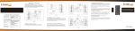
Figure 1—Controller board wiring diagram
BEST ACCESS SYSTEMS
Indianapolis, Indiana
Locking device Reader
output
output
See Note A
Table A and
Table B.
See Note A.
{
Alarm
output
{
NC & COM
de-energized
NO & COM
de-energized
NC & COM
de-energized
Note A: To determine the appropriate wire
gauge and length, refer to Minimum
Gauge Wire Chart for Lock Circuits.
Terminals to use
Jumper setting to use
See Note B.
NO & COM
de-energized
NC & COM
energized
Note B: We recommend you use 22 AWG
shielded cable no more than 500' long.
NO & COM
energized
©
OFF
ON
OFF
Note C
Note C
Motorola Weigand
HID ABA reader with HID ABA card
HID ABA reader with HID 26 bit Weigand card Note C
HID ABA reader with HID 37 bit Weigand card Note C
OFF
ON
OFF
OFF
OFF
OFF
OFF
OFF
OFF
S5
S6
ON
Note D
Note D
Note D
Note D
Note D
Note D
Note D
Note C: Use switch 1 to set the LED and sounder output for various readers. See Reader Output
on page 2.
Note D: Use switch 6 for handheld terminal communications only. Leave the switch in the off
position normally.
ON
OFF
OFF
OFF
OFF
ON
OFF
ON
ON
OFF
Do not move switches 1–5
ON
Note C
Handheld Terminal communications
OFF
Note C
Essex, KTP-71212XX
Motorola ABA
ON
ON
Mercury Security, MR-5
ON
S3
ON
S2
S1
Note C
Reader
S4
Connect to remote RS-232 connector. Or, to communicate
with a PC, connect to palmtop cable or laptop cable.
RS-232
connector
Connect all cable shields to the grounding
screw. Then connect the grounding screw
to earth ground.
Grounding
screw
Request-to-exit
unlock input
Door status/
latch monitor
input
Tamper switch
input
Remote unlock
input
Spare input
See Note B.
To communicate with a
handheld, connect to
handheld cable.
DIP switches See Table C.
Handheld
connector
Table C—Standard reader DIP switch settings
Reader power
jumper
Caution: To avoid injury, do not
touch the heat sink. It may be hot.
Reader Reader
communi power
cations output
input
During power failure at the central controller
Fail-safe locking device should be
Fail-secure locking device should be
locked
unlocked
locked
unlocked
Table B—Controller and locking device have two separate power supplies
Terminals to use
Jumper setting to use
During power failure at the central controller
Locking device is fail-safe Locking device is fail-secure
Table A—Controller and locking device share one power supply
Caution: To prevent damage and
injury, connect the power supply
after all other connections have
been made.
Connect to 12 to 24 V AC/DC
power supply. See Note A.
Power input
Locking device jumper
See Table A and B
{
{
{
{
Caution: To prevent damage,
always wear a properly grounded
electrostatic discharge (ESD)
wrist strap when installing the
controller.
Backup battery
input
{
{
{
{
{
{
T61920/Rev A 1768984 ER-7991-1