1
CHAPTER 2
MAINTENANCE I TUNE UP
Maintenance Schedule, 500 Mile ............... 2.1
Maintenance Schedule, 1500 Mile .............. 2.2
Recommended Maintenance Products .......... 2.3
Intake Filter .................................. 2.4
Lubrication ................................... 2.5
Water Pump Belt - Domestic ................... 2.6
Water Pump Belt- Fuji ........................ 2.7
Chaincase . . . . . . . . . . . . . . . . . . . . . . . . . . . . . . . . . . . 2.8-2.9
Suspension Lubrication . . . . . . . . . . . . . . . . . . . . . . . . 2.1 0-2.11
Cooling System . . . . . . . . . . . . . . . . . . . . . . . . . . . . . . 2.12
Track Maintenance/Alignment . . . . . . . . . . . . . . . . . . 2.13-2.17
Spark Plugs . . . . . . . . . . . . . . . . . . . . . . . . . . . . . . . . . . 2.18
Drive Belt Removal/Installation ................. 2.19
Backrest Adjustment .......................... 2.20
Headlight Adjustment ......................... 2.21-2.22
Bulb Replacement ............................ 2.22
Handlebar Adjustment . . . . . . . . . . . . . . . . . . . . . . . . . 2.23
Brakes . . . . . . . . . . . . . . . . . . . . . . . . . . . . . . . . . . . . . . 2.24-2.26
Reverse Maintenance . . . . . . . . . . . . . . . . . . . . . . . . . 2.27-2.28
Off Season Storage ........................... 2.29-2.31
Variable Exhaust Systems . . . . . . . . . . . . . . . . . . . . . 2.32-2.34
Routing Diagrams ............................ 2.35-2.71
MAINTENANCE/TUNE UP
Maintenance Schedule
500 Mile (805 km) Initial Maintenance Inspection
_17a.Brakes-Hydraulic
1.
Check cylinder head and base area for signs of exhaust
or coolant leaks.
A. Check brake fluid level.
_2.
Re-torque cylinder heads (cold) & cylinder base nuts
B. Check for proper hose routing; tighness of banjo bolts
and line fasteners.
_3.
Check ignition timing
C. Check for system fluid leaks.
observed BTDC
D. Visually inspect pads for wear damage or looseness.
corrected BTDC
E. Check security and surface condition of brake disc.
17b.Brake-Mechanical
_4.
Check clutch offset (belt removed)
_5.
Check belt condition
_6.
Check and adjust belt tension
B. Check brake pad and brake disc condition and mounting.
_7.
Inspect rubber engine mounts
C. Adjust brake to proper specifications.
_8.
Torque engine mounting plate to chassis fasteners
9.
10.
A. Check cable condition I routing.
18. Check auxiliary shut-off switch.
Adjust engine torque stop (if equipped)
19. Perform throttle safety switch tests.
Carburetor Inspections
20. Check brake light for proper operation.
A.
Adjust choke plungers
_21. Check tail lights.
B.
Adjust pilot air screw
_22. Check headlamp fasteners and high-low beam operation.
c.
Synchronize carburetor slide valves at idle
23. Liquid cooled models:
and off idle
A. Check coolant level and specific gravity.
D.
Adjust engine idle RPM
B. Check water pump drive belt condition & deflection
E.
Adjust throttle lever free play
(where applicable).
C. Check coolant hose, routing and clamps.
F.
Synchronize oil pump lever
G.
Inspect choke/throttle cables
D. Inspect heat exchangers condition and fasteners.
H.
lnpect vent lines for wear or kinking
E. Check cooling system for proper coolant circulation.
_24. V.E.S. (Variable Exhaust System) - if applicable.
11.
Check ski toe alignment
12.
Torque and inspect all steering fasteners
A. Disassemble and clean components.
13.
Torque suspension-to-tunnel mounting bolts
ACCS
14.
Check rear suspension fasteners for tightness
A. Inspect vent lines, clamps.
15.
Adjust track tension and align track
16.
Recommendations
Remove chaincase cover, flush chaincase, inspect
and adjust chain, refill with new chaincase oil.
Polaris Service Technician _ _ _ _ _ _ _ _ _ _ _ _ __
Base Inspection Price _ _ _ _ _ __
Authorized Dealer _ _ _ _ _ _ _ _ _ _ _ _ _ _ __
Parts _ _ _ _ _ _ _ _ _ _ _ __
Date _ _ _ _ _ _ _ _ _ _ __
Labor _ _ _ _ _ _ _ _ _ _ _ _ __
Polaris Industries Inc.
2.1
10/98
MAINTENANCE/TUNE UP
Maintenance Schedule
1500 Mile (2400 km) Maintenance Inspection
1.
_2.
_3.
_4.
_5.
_6.
_7.
_8.
_9.
_10.
11.
_12.
13
_14.
15.
16.
17
_18.
19.
_20.
_21.
Check cylinder head and base area for signs of exhaust or
coolant leaks.
Re-torque cylinder heads & cylinder base nuts (cold).
Check compression and record readings.
_21a. Brakes-Hydraulic
A. Check brake fluid level.
B. Check for proper hose routing; tighness of banjo bolts and line
fasteners.
C. Check for system fluid leaks.
D. Visually inspect pads for wear damage or looseness.
Check ignition timing.
observed BTDC
corrected BTDC
Inspect recoil starter rope ..
E. Check security and surface condition of brake disc.
F. Flush brake fluid and change every two years.
_21b. Brake-Mechanical
A. Check cable conditions I routing.
Check drive to driven clutch offset (belt removed).
Remove clutches, disassemble & inspect all wear
surfaces. Clean sheaves, repair clutch as necessary,
reassemble clutches and torque to specifications.
Check belt condition.
Check and adjust belt deflection.
Inspect rubber engine mounts.
Torque engine mounting plate to chassis fasteners.
Adjust engine torque stop (if equipped) (0.10"-0.30").
Carburetor Inspections.
A.
Adjust choke plungers.
B.
Adjust pilot air screw.
C.
Synchronize carburetor slide valves at idle.
and off idle.
D.
Adjust engine idle RPM.
E.
Adjust throttle lever free play.
F.
Synchronize oil pump lever.
G.
Inspect Choke/Throttle Cables.
H.
Inspect vent lines for wear or kinking.
Remove chaincase cover, flush chaincase, inspect.
and adjust chain, refill with new chaincase oil.
Change primary fuel filter and oil filter.
Check fuel and oil line condition and routing.
Inspect fuel and oil tank vent lines/routing.
Inspect airbox fitiair filter. Clean or replace.
Change shock oil (Fox) annually before storage.
V.E.S (Variable Exhaust System) - if applicable.
A.
Disassemble and clean components.
ACCS
A.
_22.
_23.
_24.
_25.
_26.
_27.
_28.
_29.
_30.
_31.
_32.
_33.
Inspect vent lines.
_34.
_35.
_36.
_37.
Polaris Service Technician: _ _ _ _ _ _ _ _ _ __
Authorized Dealer: _ _ _ _ _ _ _ _ _ _ _ _ __
Base Inspection Price: _ _ _ _ _ _ _ _ _ _ __
Parts: _ _ _ _ Labor: _ _ _ __
Date:
_38.
_39.
_ 40.
_ 41.
B. Check brake pad and brake disc condition and mounting.
C. Adjust brake to proper specifications.
Check auxiliary shut-off switch & perform throttle safety
switch tests.
Inspect brake light, taillight, oil light and all electrical accessories.
Inspect Hi!Lo beam operation and aim headlight; check fasteners.
Liquid cooled models:
A. Check coolant level and specific gravity.
B. Check water pump drive belt condition & deflection
(where applicable).
C. Check coolant hose, routing and clamps.
D. Inspect heat exchangers condition and fasteners.
E. Check cooling system for proper coolant circulation.
F. Replace recovery line filter: NOTE: Must use correct filter.
G. Check coolant recovery line one way check valve (must hold
pressure) where applicable.
H. Pressure test cooling system.
Fan Cooled: Inspect cooling fins and shrouds.
Remove chaincase cover, flush chaincase, inspect chain & sprockets and adjust chain. Inspect chaincase seals.
Check condition of drive shaft and jackshaft bearings. Lubricate
greaseable bearings with Premium All Season grease.
Inspect and adjust reverse cable (if applicable).
Remove ski pivot bushings and lubricate.
Inspect ski wear bars.
Check camber alignment and lubricate spindles.
Remove radius rod end bushings, lubricate and reinstall, inspect all
radius rod ends.
Reinstall skis and inspectiadjust toe alignment.
Check handlebar centering and lubricate all steering pivots.
Torque tie rod end bolts and jam nuts.
Inspect steering arms and torque bolts. Inspect handlebar bolt
torque.
Lubricate rear suspension pivot shafts.
Torque suspension mounting bolts and check all rear suspension
fasteners and components.
Inspect rear suspension wheels, bearings and hi-fax.
Inspect track for damage. Adjust tension and alignment.
For optimum performance and reliability, repeat the above maintenance and inspections annually (preferably before off-season storage) or every 1000 miles, except where noted.
RECOMMENDATION:---------------
10/98
2.2
Polaris Industries Inc.
MAINTENANCE/TUNE UP
Recommended Maintenance Products
Recommended Maintenance Products
ENGINE OIL
Description
Part#
RETAINING/SEALING PRODUCTS
Packaging
{size I quantity)
Part#
Description
Packaging
(size/quantity)
2871721
Synthetic 2-Cycle Premium Gold
Quarts/ 6
2870652
Fuel Stabilzer
16 oz/ 12
2871722
Synthetic 2-Cycle Premium Gold
Gallon I 4
2872280
Fuel Stabilizer
2.5 Gallon I 2
2871723
Synthetic 2-Cycle Premium Gold
16 Gallon Drum
2871027
Corrosion Resistant DiElectric
Grease
2 oz
2871884
Synthetic 2 Cycle Premium Gold
55 Gallon Drum
2871064
T-9 Metal Protectant
each
2871098
Premium 2-Cycle Oil (TC-W3)
Quart Cans I 12
2870632
Metal Polish
10 oz I each
2871097
Premium 2-Cycle Oil (TC-W3)
Gallon I 6
2871076
Battery Tender'"
8 oz
2871240
Premium 2-Cycle Oil (TC-W3)
2.5 Gallon I 2
2870585
Primer N, Aerosol
25 gr I 1
2871566
Premium 2-Cycle Oil (TC-W3)
16 Gallon Drum
2870584
680 Retaining Compound
10cc I each
2871385
Premium 2-Cycle Oil (TC-W3)
30 Gallon Drum
2871949
Threadlock 242
50cc I 10
2871096
Premium 2-Cycle Oil (TC-W3)
55 Gallon Drum
2871950
Threadlock 242
6cc I 12
2871281
Premium-4 Synth. 4 Cycle Oil (OW-40)
Quarts/ 12
2871951
Threadlock 262
50cc I 10
2871567
Premium-4 Synth. 4 Cycle Oil (OW-40)
16 Gallon Drum
2871952
Threadlock 262
6cc I 12
2871844
Premium-4 Synth. 4 Cycle Oil (OW-40)
Gallon/ 4
2871953
Threadlock 271
6cc I 12
2871818
Premium-4 Synth. 4 Cycle Oil (OW-40)
55 Gallon Drum
MAINTENANCE PRODUCTS
2871954
Threadlock 271
36cc I 6
2871955
Instant Adhesive: Prism 401
3cc I 30
2871326
Carbon Clean Plus
12 oz I 12
2871956
Pipe Sealant 565
50cc I 6
2871478
Premium Synthetic Gearcase Lube
12oz/12
2871957
Silicone, Black RTV
3 oz tube I 12
2871477
Premium Synthetic Gearcase Lube
Gallon I 4
2871958
Silicone, Black RTV
11 oz Cartridge/12
2872275
Premium Synthetic Gearcase Lube
2.5 Gallon I 2
2871959
Ultra Blue RTV
3.35 oz I 12
2871280
Chain Case Lubricant
Quart/ 12
2871960
Ultra Blue RTV
13 oz Cartridge/12
2870464
Chain Case Lubricant
Gallon I 6
2871961
518 Flange Sealant
50cc I 10
2871323
Premium Antifreeze 60/40 Premix
Gallon/ 6
2871534
Premium Antifreeze 60/40 Premix
Quart I 12
2870587
518 Gasket Eliminator
50cc
2870995
Premium Gas Shock Oil
Quart I 6
2871557
3 Bond 1215
5oz
2872279
Premium Gas Shock Oil
2.5 Gallon I 2
2870990
Premium Brake Fluid DOT-3
12oz/ 12
2871967
Synthetic Lube Value Pack
4 I Value pack
2870791
Premium Fogging Oil (spray)
12oz/12
2871593
TC-W3 Lube Value Pack
4 I Value pack
2871517
Premium Fogging Oil (liquid with spout)
Quart I 12
2871518
Premium Fogging Oil (liquid)
Gallon I 6
2871589
Revival/Detailing Kit
6 I Kit
2871312
Grease Gun Kit (All Season)
3 oz I 4
2871966
Restore polish/scuff remover
12 I 12 oz.
CRANKCASE SEALANTS
VALUE PACKS
WAX AND POLISH
2871322
Premium All Season Grease
3 oz I 24
2871965
Reflect Wax Final Finish
12/12oz.
2871423
Premium All Season Grease
14 oz I 10
2871964
Renew vinyl rubber protector
12/12oz.
2871460
Premium Starter Grease
2 oz I 12
2871592
Barrel Pump (for 16/30/55 gal. drums)
Each
2871285
Flex Spout (fits gal. and 2.5 gal. jugs)
25
2870505
Isopropyl
10 oz I 24
Polaris Industries Inc.
2.3
10/98
MAINTENANCE/TUNE UP
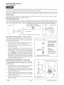
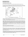
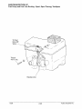
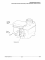
Intake Filter
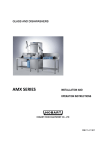
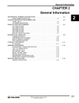
The intake foam filter limits snow ingestion into the intake system. When operating in loose powder snow, check
top of foam filter periodically to remove any accumulation of snow.
Do not operate machine with the intake filters removed. This can cause carburetor icing resulting in poor fuel
economy or carburetor malfunction.
'
'
~
~
~
~~~~
~~
2
2
2
3
1
··~
------
~
'
-:-~/
;
~ - ~/-----
/
~~/
,~J~
\
2
-----._\
-,,
4
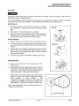
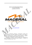
1. Intake Foam Filter
2. Air Intake Box
3. Air Plenum
4. Dash Cowl
Under Hood Air Intake System
The Indy 340, Indy 340 Deluxe, and Indy 340 Touring are equipped with an under hood air intake system which should normally be left open. The door
should be closed and latched above 35° F (2° C) for
maximum performance during warm weather operation. Simply pull the strap out and up to latch the
door. Reverse the procedure to open it.
10/98
2.4
Polaris Industries Inc.
MAINTENANCE/TUNE UP
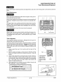
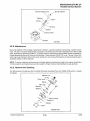
Lubrication
Lubricate the following fittings with Polaris Premium All Season
grease annually or approximately every 1000 miles (1600 km).
Remove weight from the component being greased to permit
better penetration and flushing of the joint.
Ski Spindles and Bushings
~
• Spindles, left and right.
• Rear suspension pivot shafts.
• Lubricate both front ski pivots at fitting as shown using low
temperature grease.
Trailing '97+
• Grease jackshaft and driveshaft (clutch side) bearings.
@J
• Grease steering post support bracket bushings.
Leading Type
Typical Spindle
• Grease center steering arm (bell crank), pitman arm, and idler
arm (where applicable).
Pitman Arm
Idler Arm
NOTE: A grease gun kit complete with grease and adaptors is
available to lubricate all fittings on Polaris snowmobiles.
Polaris Premium All Season Grease
14 oz. PN 2871423
Center Steering Arm
(Bell Crank)
Grease Gun Kit PN 2871312
Bushings
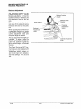
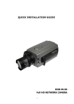
Jackshaft Bearing Greasing
Loosen driven clutch retaining bolt and pull clutch outward to expose bearing. Use a point type grease gun fitting to inject grease
through hole in flangette into bearing until grease purges out inside or outside bearing seal. Push clutch back onto shaft and replace clutch retaining bolt.
Grease
Grease Gun Adapter: 2871174
PointType
'
Jackshaft Bearing
Driveshaft Bearing Greasing
Inject grease into fitting on speedometer drive adaptor until
grease purges out inside or outside bearing seal.
Driveshaft Bearing Greasing - WideTrak
Jackshaft coupler
··~
,/ _______ Drive
Ct.- _____
shaft~
WideTrak
Polaris Industries Inc.
2.5
10/98
MAINTENANCE/TUNE UP
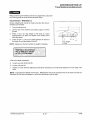
Water Pump
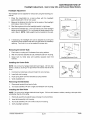
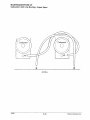
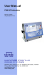
Water Pump Belt Tension -
Replace if width is less than .25"
(6.35mm). Nominal new width is
.345" (8.75mm).
600/700 Domestic Twins
The water pump belt on all 600 & 700 domestic twins
snowmobile engines should be inspected every 1500
miles. Belts should be inspected by measuring the width
at several locations around the belt. Belt width at any
location should not be thinner than .250" (6.35mm). Replace the belt if you notice any loose cords, broken
cracked or missing cogs, and variations in width. If the
water pump belt fails, serious engine damage could result. Nominal thickness of a new belt should be approximately .345" (8.75mm).
Check belt tension by rotating crankshaft 1/8 turn at a
time. The tension should be equal at all points of rotation.
1.
2.
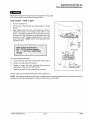
A weight is needed to test belt deflection. Construct a
weight out of wire and weights such as thick washers.
Use the illustration to assist you . The finished weight
should weigh 2 lbs.
Weight Construction
I
Measure the belt deflection using the following
procedure:
I
a. Hang weight midway between pulleys. Weight
must hang free and not rest on any part of machine.
b.
Lay a straight edge or straight piece of stiff material (steel is suggested) across the top of both pulleys. The straight edge should measure approximately 1/8" x 8" x 1".
c.
Measure the gap between the belt and the
straight edge at the point where the weight is
hanging.
d.
Measured distance must be between .1" and
.25". If the measured distance is more than the
specification, try another waterpump belt.
I
~
.062" to .090"
Wire Suggested
Wide Enough
to Span Belt
3J
Weight should equal 2 lbs.
Hang Weight Here
NOTE: Do not use tools to assemble belt on pulleys.
Damage can occur which could shorten belt life. Before
installing new belt, check pulley teeth, remove all foreign
material, dirt, and oil. Never install a used belt on a different engine. Install belt so writing on the belt can be read
from the right side of the machine.
10/98
2.6
Polaris Industries Inc.
MAINTENANCE/TUNE UP
Water Pump
Water Pump Belt Tension-
Fuji
Loosen pump mounting bolts.Push on pump housing to
apply tension to belt and hold in this position. Tighten
pump mounting bolts.Apply light pressure at center of
belt span. Check total deflection of belt span and
compare to specifications. Re-adjust if necessary.
Water Pump, Belt .Tension
1/8"- 3/16"
Oil Pump Adjustment
Refer to Page 3.83 for oil pump adjustment procedure.
Polaris Industries Inc.
2.7
10/98
MAINTENANCE!TUNE UP
Chaincase
Chaincase Oil Level (All Except WideTrak Models)
The Indy models have a silent chain design. The drive chain is continuously immersed in oil. Proper oil level is determined by checking the
level on the dipstick with machine placed on a level surface. The oil
level should be between the "safe" marks on the dipstick. Add oil
through dipstick opening to maintain proper level. Use Polaris synthetic chaincase oil. Do not overfill.
B
Polaris Synthetic Chaincase Lubricant
Gallon PN 2871477
12 oz. PN 2871478
E---~
Magnetic Plug
Ill. 1
Polaris Synthetic Chaincase Lubricant is compatible with our petroleum based chaincase oil and can be mixed. However, do not mix
or use other types of lubricant. Excessive wear to chain, sprockets
and bearings may result.
Drive Chain Tension - Chaincase cover on
To obtain correct chain tension:
1.
Elevate rear of machine so track is off floor.
2.
Loosen locknut and chain adjuster.
3.
Back off adjuster bolt 1/2 turn. (For models with reverse, back off adjuster bolt 1 1/4 to 1 1/2 turns)
4.
Hold adjuster bolt in position and tighten locknut.
Drive Chain Tension - Chaincase cover removed
To obtain correct chain tension:
1 . Remove drain plug (F) and drain oil into a suitable container.
Dispose of properly.
2.
Remove the chaincase cover.
3.
While putting a slight reverse tension on the chain by turning brake disc as indicated by the arrow (A), there
should be approximately 1/4-3/8" (.6-1 em) deflection on the chain at point (B). Refer to illlustration 1.
4.
The chain is adjusted by loosening the adjusting bolt locknut (C) and turning adjusting bolt (D) until correct
chain deflection is obtained.
5.
Lock the adjusting bolt locknut (C) while holding a wrench on the adjusting bolt (D) to prevent it from turning.
6.
Reinstall the chaincase cover and drain plug. Add Polaris synthetic chaincase lubricant (PN 2871478)
through the dipstick opening to the level described above.
NOTE: Clean the magnetic plug (E) every 500 miles (800 km) and whenever checking or changing lubricant.
10/98
2.8
Polaris Industries Inc.
MAINTENANCE/TUNE UP
Chain case
Chaincase Oil Level (WideTrak Models)
Using Polaris Synthetic Chaincase Lubricant, maintain the proper oil
level. Proper oil level is determined by checking the level on the dipstick (A) with the machine placed on a level surface. The oil level
should be between the "safe" marks on the dipstick. Add oil through
the dipstick opening to maintain proper oil level. Do not overfill.
NOTE: Clean the magnetic plug (B) every 500 miles (800 km) and
whenever checking or changing lubricant.
Polaris Synthetic Chaincase Lubricant
Gallon PN 2871477
12 oz. PN 2S71478
~
B
Polaris Synthetic Chaincase Lubricant is compatible with our petroleum based chaincase oil and can be mixed. However, do not mix
or use other types of lubricant. Excessive wear to chain, sprockets
and bearings may result.
Polaris Industries Inc.
2.9
10/98
MAINTENANCE!fUNE UP
Suspension Lubrication
Suspension Lubrication
To maintain rider comfort and to retard wear of the pivot shafts, the suspension pivot shafts should be lubricated
with Polaris Premium All Season Grease, PN 2871423, at 500 miles (800 km) initially; 1000 miles (1600 km) and
before summer storage each year. The riding characteristics of the snowmobile will be affected by lack of lubrication of these shafts. NOTE: A grease gun kit complete with grease and adaptors is available to lubricate all fittings
on Polaris snowmobiles. Order PN 2871312.
Polaris Premium Grease PN 2871423
Grease Gun Kit PN 2871312
Refer to the following diagrams for suspension lubrication points.
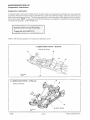
* LUBRICATION POINTS - WideTrak
Grease all fittings
*
*
-
Forward
*
* LUBRICATION POINTS- XTRA-Lite
* *
Grease all fittings
*
*(Both Sides)
~rward
10/98
2.10
Polaris Industries Inc.
MAINTENANCE/TUNE UP
Suspension Lubrication
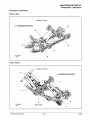
Suspension Lubrication
XTRA 10 Style
Grease at fittings
* LUBRICATION POINTS
*
*
*
*
*
-
Forward
*
XTRA 12 Style
Grease at fittings
* LUBRICATION POINTS
*
*
-
Forward
Polaris Industries Inc.
*
*
(Both sides)
*
2.11
10/98
MAINTENANCE/TUNE UP
Cooling System
A
WARNING
Never remove the pressure cap when the engine is warm or hot. If the pressure cap is to be removed, the engine
must be cool. Severe personal injury could result from steam or hot liquid.
Use of a non-standard pressure cap will not allow the recovery system to function properly. If the cap should need
replacement, install the correct Polaris cap with the same pressure rating. Refer to the appropriate parts manual.
Coolant Level
Coolant level in the reservoir or surge tank must be maintained between the minimum and maximum levels to
prevent overheating and serious engine damage.
Recommended Coolant
Use a 50/50 or 60/40 mixture of antifreeze and distilled water depending on the freeze protection required for your
area. Do not use tap water in the system or reduced cooling or filter contamination may result. Replace coolant
every 2 years or if contaminated. Inspect coolant filter annually for contamination and replace if necessary.
COOLANT
0
Check Valves - tapered
side points in flow direction
somE
'
\
' __.Flow
Check Valve
Filter
Filter - Filter is located before the check valve
Bleeding the Cooling System - Pressure Caps
If the cooling system should become low in the tank and/or
filler neck, the system should be bled of any trapped air using the following procedure:
1.
Allow the system to cool completely. Fill the reseNoir
with coolant to the maximum indicated mark.
2.
With pressure cap removed, add coolant and fill to the
top of the filler neck.
3.
Install the pressure cap with the lever lock up in its
release position and run the engine at fast idle for two
to three minutes. This will purge the system of trapped
air. Close the lever lock and check recovery tank fluid
level. CAUTION: On models equipped with remote
filler neck, low idle RPM must be used for bleeding
(600 RPM ± 100) to allow all air to purge and prevent
trapped air which can lead to overheating. Reset idle
to specified RPM after bleeding.
Lift Lock Lever To Bleed
~
I
f1
~
J
..
Remote Filler Neck
Bleed at 600 RPM
Filler Neck On
Cylinder Head
Bleed at fast idle
Caution:
Increase RPM
slowly when lever
lock is up to avoid
loss of coolant.
Remote Filler Neck Shown
Bleeding the Cooling System - Surge Tanks
Manifold Bleed Screw
If the cooling system should become low in the surge tank,
the system must be bled of any trapped air using the following procedure:
1.
Allow the system to cool completely. Fill the surge tank
with coolant to the maximum indicated mark.
2.
Start the engine and loosen the bleed screw on the top
of the water pump until trapped air has been purged.
Tighten the bleed screw.
3.
Loosen the bleed screw at the end and top of the water
outlet manifold until trapped air has been purged.
Tighten the bleed screw.
4.
Recheck the surge tank coolant level and add coolant
again if necessary.
10/98
2.12
I
Fill Surge Tank
Polaris Industries Inc.
MAINTENANCE/TUNE UP
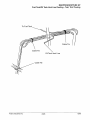
Track Maintenance/Alignment
A
WARNING
When performing the following checks and adjustments, stay clear of all moving parts to avoid serious personal
injury.
Track Maintenance
A
WARNING
Never make this maintenance check with the engine running as serious personal injury can result.
2 1
3
1 2
Using a hoist, safely lift and support the rear of the snowmobile off
the ground. Rotate the track by hand to check for any possible damage.
To inspect track rods, carefully examine the track along the entire
length of each rod, bending the track and inspecting for breakage.
The three most common places where breakage occurs are shown
in the illustration.
If any rod damage is found, the track should be replaced.
A
WARNING
Broken track rods are a serious hazard, since they can cause a rotating track to come off the machine. Never operate or rotate a torn
or damaged track under power. Serious personal injury or death
may occur.
Lug
Track window
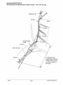
Track Alignment
Track alignment affects track tension. Misalignment will cause excessive wear to the track and slide rail.
A periodic check should be made to see that the track is centered
and running evenly on the slide rails. Misalignment will cause excessive wear to the track and slide rail. NOTE: If excessive hi-fax
wear occurs due to poor snow conditions, additional wheel kits are
available.
1.
Safely support the rear of the machine with the track off the
ground.
2.
Start the engine and apply a small amount of throttle until the
track turns slowly at least five complete revolutions. Stop the
engine.
3.
Inspect track alignment by looking through the track window to
make sure the rails are evenly spaced on each side. If the track
runs to the left, loosen left locknut and tighten the left adjusting
bolt. If the track runs to the right, loosen right locknut and
tighten the right adjusting bolt.
4.
Looking through
track window,
make sure the
rails are evenly
spaced on each
side.
Hi-fax
After adjustments are complete, be sure to tighten locknuts and
idler shaft bolts. Torque to specification.
Idler Shaft Bolt Torque 35-40 ft.lbs. (4.8 • 5.5 kgm)
Idler
Shaft Bolt
Polaris Industries Inc.
2.13
10/98
MAINTENANCE/TUNE UP
Track Maintenance/Adjustment
Track Tension Data
Suspension
Weight
Measurement Location
Measurement
XTRA 12 121"
none
2" behind rail bumper
1/2" (1.3 em)
XTRA 12 133"
none
16" ahead of rear idler shaft
1-1 1/8" (2.5- 2.9 em)
free hanging
free hanging
XTRA 10 121", 133", 136"
10 lbs. (4.54 kg)
16" ahead of rear idler shaft
3/8- 1/2" (1 - 1.3 em)
WideTrak
10 lbs. (4.54 kg)
16" ahead of rear idler shaft
3/4- 1" (1.9- 2.5 em)
XTRA Lite 121" and 133"
10 lbs. (4.54 kg)
16" ahead of rear idler shaft
3/8 -1/2" (1 - 1.3 em)
XTRA Lite 136"
10 lbs. (4.54 kg)
16" ahead of rear idler shaft
3/8- 1" (1 -2.5 em)
A
WARNING
When performing the following checks and adjustments, stay clear of all moving parts to avoid serious personal
injury.
Track Tension - XTRA Lite Style
1.
Turn the machine off.
2.
Lift the rear of the machine and safely support it off the
ground.
3.
Place a 10 lb. (4.5 kg) weight on the track at a point
approximately 16" (40.6 em) ahead of the center of the
rear idler wheel.
4.
Check for proper slack between the inside of the track clip
wear surface and the hi-fax (C). NOTE: Measure at the
point where the weight is hanging.
XTRA Lite 121" and 133"3/8- 1/2" slack (1 - 1.3 em) w/10
lb. (4.54 kg) weight
XTRA Lite 136"- 3/8-1"(1-2.5 em)
w/10 lb. (4.54 ka) weiaht
Track
1 0 lb. Weight
(4.5 kg)
If the track needs adjustment:
5.
Loosen rear idler shaft bolts (D) on both sides of the machine.
6.
Loosen track adjusting bolt locknuts (A).
7.
Tighten or loosen the track adjusting bolts (B) evenly as necessary to obtain proper track tension.
8.
Tighten idler shaft bolts and adjuster bolt locknuts.
NOTE: Track alignment affects track tension. Misalignment will cause excessive wear to the track and slide rail.
Excessive Hi Fax wear will appear on units with track tension set too tight.
10/98
2.14
Polaris Industries Inc.
MAINTENANCEfTUNE UP
Track Maintenance/Adjustment
A
WARNING
When performing the following checks and adjustments, stay clear
of all moving parts to avoid serious personal injury.
Track Tension - WideTrak LX
Tension adjustments should be made only after the track is
warmed up and limber.
1.
Turn the machine off.
2.
Lift the rear of the machine and safely support it off the
ground.
3.
Place a 10 lb. (4.5 kg) weight on the track at a point
approximately 16" (40.6 em) ahead of the center of the
rear idler wheel.
4.
Check for 3/4-1" (1.9-2.5 em) slack between the inside of
the track clip and the plastic hi-fax (C).
NOTE: Measure at the point where the weight is hanging .
10 lb. Weight
(4.5 kg)
.
WideTrak LX Track Tension 314 -1" slack (1.9 • 2.5 em)
w/1 0 lb. (4.54 kg) weight
If the track needs adjustment:
5.
Loosen rear idler shaft bolt (D).
6.
Loosen locknuts (A).
7.
Tighten or loosen the track adjusting screws (B) as necessary to provide equal adjustment on both sides of the
track.
NOTE: Track alignment affects track tension. Misalignment will cause excessive wear to the track and slide rail.
Excessive Hi Fax wear will appear on units with track tension set too tight.
Polaris Industries Inc.
2.15
10/98
MAINTENANCE/TUNE UP
Track Maintenance/Adjustment
,A
WARNING
When performing the following checks and adjustments, stay clear
of all moving parts to avoid serious personal injury.
Track Tension - XTRA 10 Style
1.
Turn the machine off.
2.
Lift the rear of the machine and safely support it off the
ground.
3.
Place a 10 lb. (4.5 kg) weight on the track at a point
approximately 16" (40.6 em) ahead of the center of the
rear idler wheel (D).
4.
Check for 3/8-1/2" (1-1.3 em) slack between the inside of
the track clip and the hi-fax (C). NOTE: Measure at the
point where the weight is hanging.
XTRA 10 121",133n, & 136"StyleTrack
Tension -318- 1/2" slack (1 - 1.3 em)
w/10 lb. (4.54 kg) weight
Track
10 lb. Weight
(4.5 kg)
If the track needs adjustment:
5. Loosen rear idler shaft bolts (D) on both sides of the
machine.
6. Loosen track adjusting bolt locknuts (A).
7.
Tighten or loosen the track adjusting bolts (B) evenly as
necessary to obtain proper track tension.
8.
Tighten idler shaft bolts and adjuster bolt locknuts.
Always inspect track alignment after track tension adjustment.
NOTE: Track alignment affects track tension. Misalignment will cause excessive wear to the track and slide rail.
Excessive Hi Fax wear will appear on units with track tension set too tight.
10/98
2.16
Polaris Industries Inc.
MAINTENANCE!TUNE UP
Track Maintenance/Adjustment
A
WARNING
When performing the following checks and adjustments, stay clear
of all moving parts to avoid serious personal injury.
Track Tension - XTRA 12 Style
1. Turn the machine off.
2.
Lift the rear of the machine and safely support it off the
ground.
3.
Take measurement with track free hanging at a point 2"
behind rail bumper or 16" ahead of rear idler on 133"
tracks. The distance between the inside top of the track
clip and the Hi-Fax should be as shown below and in the
illustration at right. Repeat measurement on the other
side of the track. NOTE: Check more frequently when
machine is new.
Rear
idler
shaft
bolt
XTRA 12 Style Track Tension 121" 1/2" (1.3 em) free hanging
133" 1 - 1 1/8" (2.54 - 2.86 em) free
hanging
Rail bumper
If the track needs adjustment:
4. Loosen rear idler shaft bolts on both sides of the machine.
5.
Loosen track adjusting bolt locknuts.
6.
Tighten or loosen the track adjusting bolts evenly as
necessary to obtain proper track tension.
7.
Track
Hi-fax
measured 16"ahead
of rear idler center
Tighten idler shaft bolts and adjuster bolt locknuts.
Always inspect track alignment after track tension adjustment.
NOTE: Track alignment affects track tension. Misalignment will cause excessive wear to the track and slide rail.
Excessive Hi Fax wear will appear on units with track tension set too tight.
Polaris Industries Inc.
2.17
10/98
MAINTENANCE!TUNE UP
Spark Plugs
Spark Plug Selection
Original equipment parts or their equivalent should always be used. However, the heat range of spark plugs is
of utmost importance. A spark plug with a heat range which is too high will cause engine damage. A spark plug
with a heat range which is too low will cause excessive fouling and malfunction.
In selecting a spark plug heat range for production, a manufacturer is forced to assume that the engine is going
to be operated under extreme heavy duty conditions. This protects the engine from internal damage in the event
that the purchaser actually does operate the engine in this manner. This selection however, could cause the customer who normally operates the engine under medium or light duty to have spark plug failure.
A plug with a heat range which is too high will always cause engine damage if the engine is operated in conditions
more severe than that for which the spark plug was intended.
A new engine can cause temporary spark plug fouling even though the heat range is correct, due to the preservative which has been added during assembly of the engine to combat rust and corrosion. Avoid prolonged idle
speeds, as plug fouling and carbonization will result. Always use resistor type spark plugs.
NOTE: Incorrect fuel mixture can often cause a spark plug to appear to be too dark or too light in color. Before
changing spark plug heat ranges, be sure the correct main jet is installed in the carburetor(s).
The spark plug and its condition is indicative of engine operation. The spark plug firing end condition should be
read after the engine is warmed up and the vehicle is driven at higher speeds. Immediately check the spark plug
for correct color.
Normal
The insulator tip is gray, tan, or light brown. There will be a few combustion deposits. The electrodes are not
burned or eroded. This indicates the proper type and heat range for the engine and the service.
NOTE: The tip should not be white. A white insulator tip indicates overheating, caused by use of an improper
spark plug or incorrect carburetion adjustments.
Wet Fouled
The insulator tip is black. A damp oily film covers the firing end. There may be a carbon layer over the entire
nose. Generally, the electrodes are not worn. General causes are excessive oil, use of non-recommended injection oil, excessive idling, idle too low or too rich, or weak ignition output.
1.
Inspect electrodes for wear and carbon buildup. Look for a sharp outer edge with no rounding or erosion of the
electrodes.
2.
Clean with electrical contact cleaner or a glass bead spark plug cleaner only.
A wire brush or coated abrasive should not be used.
3.
Measure gap with a wire gauge and adjust to specifications by bending side electrode carefully.
4.
Coat spark plug threads with a small amount of anti-seize compound.
5.
Install spark plug and torque to specification.
Spark Plug Torque:
11 Ft. Lbs (1.52 kg-m)
10/98
2.18
Polaris Industries Inc.
MAINTENANCE!TUNE UP
Drive Belt Removal/Installation
Drive Belt
A
WARNING
Inspect the condition of the drive belt. Inspect clutch sheaves for damage, wear, or belt residue. Clean with non-oil
base cleaner such as isopropyl alcohol.
To ensure satisfactory belt life, install belts so they operate in the same direction of rotation. Position the identification numbers so that you can read them. This will keep the belt rotating in the same direction.
Belt Removal
1.
Be sure key switch is off and engine has come to a complete
stop. Remove the retaining knob or pin and open the clutch
guard.
2.
Apply brake (or lock parking brake if so equipped).
3.
Grasp belt firmly midway between clutches and pull upward and
rearward to open the driven clutch sheaves. Remove the belt
from the driven clutch and then from the drive clutch.
Removal
Belt Installation
1.
Drop the drive belt over the drive clutch and pull back the slack.
2.
Turn the driven clutch moveable sheave clockwise while at the
same time pushing inward and forcing the belt down between the
sheaves.
3.
Hold the belt down between the sheaves and roll the bottom
portion over the outer clutch sheave. Once installed, be sure to
work the belt to the outer edge of the sheave. Be sure to release
parking brake if applied.
4.
Close the clutch guard and reinstall the retaining knob or pin.
Installation
1.
Belt Inspection
5.
Refer to PVT Section for belt inspection and width
measurement.
6.
Measure belt length with a tape measure around the outer
circumference of the belt. Belts which measure shorter or
longer than a nominal length may require driven clutch or
engine adjustment to obtain proper belt deflection.
7.
Replace belt if worn past the service limit. Belts with thin
spots, burn marks, etc., should be replaced to eliminate
noise, vibration, or erratic operation.
See
Troubleshooting Chart at the back of this chapter for
possible causes. NOTE: If a new belt is installed, check
belt deflection. Install so part numbers are easily read.
Refer to the specification charts for belt specifications and
measurement procedures.
Polaris Industries Inc.
2.19
10/98
MAINTENANCE/TUNE UP
Backrest Adjustment
Backrest Adjustment
The passenger backrest on the
Classic Touring and XLT Touring
Models is adjustable. To move the
backrest forward or backward, lift
the adjustment lever on the left
side.
To lengthen or shorten the backrest cable, lift the cable until spring
tension is felt and lock the jamb
nut.
When adjusting the backrest from
a passenger position to a single
rider position, rotate the backrest
cushion adjustment knobs until
the proper angle is reached.
The grab bars have five height adjustments. To raise or lower the
grab bar, remove the grab bar adjuster knob, position the grab bar
at the desired height, and reinstall
the knob.
The Classic Touring and XLT Touring models are also equipped with
passenger handwarmers. The
handwarmer switch, located under the left hand wind deflector,
has three settings: high, off, and
low.
10/98
Backrest Cushion
Adjuster
Wind Deflector
Backrest Cable
Adjuster
Backrest -------+;.+="'--6f;
Adjustment
Lever
Grab Bar Adjustment
Knob
2.20
Polaris Industries Inc.
MAINTENANCEfrUNE UP
Headlight Adjustment - Gen II, Indy 340, and Evolved Style Models
Headlight Adjustment
The headlight can be adjusted for vertical aim using the following procedure:
1.
Place the snowmobile on a level surface with the headlight
approximately 25' (7.6 m) from a wall.
2.
Measure the distance from the floor to the center of the headlight
and make a mark on the wall.
3.
Start the engine and turn the headlight switch to high beam.
4.
Observe the headlight aim. The most intense part of the headlight
beam should be aimed 2" (5.1 em) below the mark placed on the
wall in Step 2. NOTE: Rider weight must be included on the seat.
5.
If necessary, the headlight aim can be adjusted by turning the
adjustment knob located inside the hood just below the headlamp
opening. Turn knob in or out as needed for proper aim.
Removing the Center Bulb
1.
Push down on spring until it releases from spring retainer.
2.
With wire harness attached to bulb, withdraw bulb from housing.
3.
Grasp bulb by metal base and carefully separate bulb from
harness.
25' (7.6 m)
~bdU
~Headlight Adjustment Knob
Installing the Center Bulb
NOTE: Do not touch a halogen bulb with bare fingers. Oil from skin
leaves a residue, causing a hot spot which will shorten the life of the
lamp.
1.
Hold bulb by metal base only and install into wire harness.
2.
Insert bulb into housing.
3.
Push spring down until it is secured by spring retainer.
4.
Verify headlight aim.
a1
Wire
H~ss ~/~~
~r ""'b
Spring
Removing the Side Bulbs
1.
Disconnect terminal from back of bulb.
2.
Turn bulb assembly 1/4 turn to right and withdraw from housing.
Installing the Side Bulbs
NOTE: Do not touch a halogen bulb with bare fingers. Oil from skin leaves a residue, causing a hot spot which
will shorten the life of the lamp.
1.
Hold bulb assembly by plastic base and plug into wire terminal.
2.
Insert bulb assembly into housing.
3.
Turn bulb assembly 1/4 turn to left to secure in housing.
4.
Verify headlight operation.
Polaris Industries Inc.
2.21
10/98
MAINTENANCE!TUNE UP
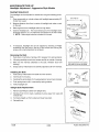
Headlight Adjustment - Aggressive Style Models
Headlight Adjustment
The headlight can be adjusted for vertical aim using the following procedure:
1. Place snowmobile on a level surface with headlight approximately 25'
(7.6m) from a wall.
2.
Measure distance from floor to center of headlight and make a mark
on the wall.
3.
Start engine and turn headlight switch to high beam.
4.
Observe headlight aim. The most intense part of the headlight beam
should be aimed 2" (5.1 em) below the mark placed on the wall in Step
2. NOTE: Rider weight must be included on the seat.
5.
If necessary, headlight aim can be adjusted by inserting a Phillips
screwdriver into the boss in the top of the console and turning the
screw until correct adjustment is achieved.
25' (7.62 m)
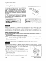
Removing the Bulb
1.
Push down on left side of spring until it releases from spring retainer.
2.
Lift spring carefully around wire harness and flip to outside of housing.
3.
With the wire harness attached to the bulb, withdraw bulb from
housing.
4.
Grasp bulb by metal base and carefully separate bulb from harness.
Insert screwdriver into access
hole and turn screw to adjust
Installing the Bulb
1.
Hold bulb by metal base and install into wire harness.
2.
Insert bulb into housing.
3.
Carefully flip spring back into housing placing it around wire harness.
4.
Push spring down until it is secured by spring retainer.
5.
Verify headlight aim.
~~
I ~--: I
W
B"lb
Wire
Harness
Spring
Taillight Bulb Replacement
Lens
1.
Remove (5) Phillips screws from taillight lens.
2.
Working from front to back, carefully pry lens away from seal and
remove lens.
3.
Pull bulb straight out from socket and insert new bulb.
4.
Reinstall lens.
10/98
2.22
Polaris Industries Inc.
MAINTENANCE!TUNE UP
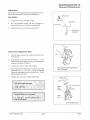
Handlebar Adjustment
Handlebar Adjustment - Evolved and Aggressive Style Models
1.
Remove two plastic fasteners holding console cover located
below handlebar cover on hood side of steering post.
2.
Using a 7/16" (11 mm) wrench, loosen four nuts on bottom of
adjuster block. NOTE: Turn handlebar to left or right for access
to rear nuts.
3.
Adjust handlebar to the desired height. Be sure that handlebars,
brake lever and throttle lever operate smoothly and do not hit the
gas tank, windshield or any other part of the machine when
turned fully to the left or right.
4.
Torque the handlebar adjuster block bolts to specification.
Maintain an equal gap on front and back of block.
5.
Replace console cover.
Bottom of Adjuster Block
Handlebar Adjustment - All Other Models
1 . Remove handlebar cover.
Socket Screws
2.
Using a 7/16" (11 mm) wrench, loosen four nuts on bottom of
adjuster block. NOTE: Turn handlebar to left or right for access
to back nuts.
3.
Adjust handlebar to the desired height. Be sure that handlebars,
brake lever and throttle lever operate smoothly and do not hit the
gas tank, windshield or any other part of the machine when
turned fully to the left or right.
4.
Torque the handlebar adjuster block bolts to specification.
Maintain an equal gap on front and back of block.
5.
Replace handlebar cover.
Handlebar Adjuster Block Bolt ,Torquei
.
i'
11 ·13 ft.lbs~ (1.5 -1.8 kgm)
A
WARNING
Improper adjustment of the handlebars, or incorrect torquing of the
adjuster block tightening bolts can cause limited steering or loosening of the handlebars, resulting in loss of control.
Polaris Industries Inc.
2.23
10/98
MAINTENANCE/TUNE UP
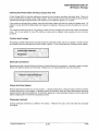
Brakes
Replenishing Brake Fluid
Remove brake fluid master cylinder reservoir cover. Add Polaris
brake fluid as required to bring the level up to the top of the fluid
level mark on the inside of the reservoir (B). The proper fluid level
is 1/4-5/16" (.6-.8 em) below the lip of the reservoir opening.
1/4-5/16"
(.6-.8 em)
B
NOTE: On some models, the brake fluid level can be seen
through the plastic reservoir. The fluid should be maintained between the minimum and maximum marks on the reservoir for
those models.
Inspect the reservoir to be sure it contains the correct amount of
fluid. Use only Polaris DOT 3 high temperature brake fluid.
Change fluid every 2 years or whenever the fluid is dark or contamination is suspected.
Master Cylinder Fluid level
Polaris DOT 3 High Temp Brake Fluid
1/4- 5/16" (.6- .8 em) below lip of
PN 2870990
reservoir opening
A
WARNING
Do not over fill the master cylinder. Fluid expansion could cause brakes to lock, resulting in serious injury or death.
Once a bottle of brake fluid is opened, use what is necessary and discard the rest. Do not store or use a partial
bottle of brake fluid. Brake fluid is hygroscopic, meaning it rapidly absorbs moisture from the air. This causes
the boiling temperature of the brake fluid to drop, leading to early brake fade and the possibility of serious injury.
Bleeding the Hydraulic Brake System
Air in the hydraulic brake system will cause a springy or spongy brake lever action. Bleeding is necessary to remove air from the system.
1.
Remove brake fluid master cylinder reservoir cover and gasket.
CAUTION: Brake fluid is a hazardous material. Contact with decals, paint, and many plastics will cause damage.
Use proper precautions when handling brake fluid.
2.
Fill the master cylinder reservoir (B) and replace gasket and cover. Keep the fluid level 1/4-5/16" (.6-.8 em)
below lip of reservoir opening.
3.
Slip a rubber tube over the ball of the bleeder valve and direct the flow of fluid into a container.
A
WARNING
Never re-use brake fluid. Brake fluid is hygroscopic, meaning it rapidly absorbs moisture from the air. This causes
the boiling temperature of the brake fluid to drop, leading to early brake fade and the possibility of serious injury.
4.
Squeeze brake lever a full stroke. Then unscrew bleeder valve
(A) 3/4 of a turn to release air.
5. Close bleeder valve first and then release brake lever.
Repeat steps 4 and 5 until fluid flows from bleeder valve in a solid
stream free of air bubbles. Do not allow reservoir to run dry or air will
be drawn into system.
6. Re-fill reservoir to proper level after bleeding operation. Do not
overfill the master cylinder.
7. Replace gasket and cover.
During the bleeding procedure make sure to keep the reservoii as level as possible to minimize the possibility of air entering the system.
10/98
2.24
Polaris Industries Inc.
MAINTENANCE/TUNE UP
Brakes
Brake Adjustment - Mechanical Disc Brakes
If excessive brake lever to brake block clearance is evident, the caliper adjuster should be adjusted using the
following method.
A
WARNING
Adjust brake with caliper adjuster bolt only. Do not adjust cable or cable sleeve length. Improper brake adjustment
could result in brake failure which could result in severe injury or death.
Caliper Adjustment
1.
Bend locking tab (A) away from lock nut (B) and loosen
lock nut.
2.
Push down on actuating lever (C) and insert a .015" feeler
gauge between the brake disc and outer brake pad.
3.
Turn adjusting bolt (D) in until a slight pressure is felt
against the feeler gauge.
4.
While holding adjusting bolt (D), tighten locknut (B).
5.
Bend locking tab (A) against locknut.
A
WARNING
Be certain locking tab is correctly positioned in actuating lever.
After locknut is tightened, check pad to disc clearance to be
certain there is .015" clearance.
Be certain brake pads are not dragging on disc and brake lever
travel is not excessive.
Improper brake adjustment could result in brake failure which
could result in severe injury or death.
Brake Pad to Disc Clearance .015" (.38 mm)
.015" Feeler Gauge
NOTE: Replace pads when worn beyond service limit.
Minimum Pad
Thickness
Brake Pad Thickness - Type M3
shown.
Service Limit .250" (6.35mm)
(All brake pads)
Polaris Industries Inc.
.250"
(6.35mm)
2.25
10/98
MAINTENANCEffUNE UP
Brakes
WT-2 Brake Adjustment
1.
Check to ensure floating parts move freely and that
all other parts are mounted securely. Tighten
hardware as required.
2. Check actuator linkage to ensure there is adequate
freedom of movement for positive brake operation.
Periodic adjustment of pad gap can be performed
using actuating cable.
3. Loosen lock nuts.
Lock
Nuts
Move cable up or
down in bracket
to adjust freeplay
4. To increase brake lever free play turn nuts
counterclockwise to move cable down in bracket.
To decrease lever free play move cable up in
bracket. Tighten lock nuts.
Brake Lever Free Play
1/4-318 in. (6-10mm)
5.
6.
7.
8.
9.
10.
11.
12.
If cable adjuster has reached maximum (used up),
the lever arm can be re-indexed. Loosen lock nuts
and turn counterclockwise (as viewed from top) to
obtain the maximum amount of cable freeplay.
Straighten tab on tab washer and loosen bolt
enough to disengage actuator lever spline.
Slip long leg of lever spring off caliper and rotate to
the side.
Rotate the lever one tooth in the direction opposite
the actuation direction, and tighten bolt making
sure spline teeth are properly engaged.
Bend up a tab aligning with one of the bolt head flats
to prevent bolt rotation.
Return the spring to its original position on the
caliper. Both lever and linkage must be free to
return to original position.
Perform steps 3. and 4. to adjust lever freeplay.
Verify proper brake operation. Disc should rotate
freely without drag.
Check disc surface condition. Refer to Brake/Final
Drive section to inspect disc and pad condition and
thickness.
10/98
2.26
1/4-3/8" (6-10 mm)
Spring
Lever S pnng
.
C~;m~p
M~hing
~)J ; ~
~'\Lifter
00
o
....-; ~
~
\
Tab Washer
Balls
~
~
~-~
Separator
Plate
<::J.
~
Polaris Industries Inc.
MAINTENANCE/TUNE UP
Reverse Kit Maintenance
Adjustment
Due to break-in or replacement of components, the reverse shift mechanism may require adjustment.
Shift Lever
GenII Style
1.
Loosen jam nuts on linkage rod (A).
2.
Turn the threaded linkage rod (B) to lengthen or
shorten the throw until reverse engages fully.
3.
Tighten jam nuts and re-check adjustment.
Clevis Pin
J
+--- Shift Lever
Actuator
Evolved and Aggressive Style
1.
Lift shift lever slowly while observing shift arm on
transmission.
2.
If adjustment is correct, shift will move 1 - 1 1/2"
before the shift arm begins to move. If adjustment is
required, proceed with step 3.
3.
Loosen jam nuts on lower end of cable.
4.
Adjust cable end at transmission until the end of the
shift lever has 1 - 1 1/2" (2.5 - 3.8 em) of freeplay
before the cable starts to move the shift arm. Do not
adjust beyond this point.
5.
Tighten jam nuts and re-check adjustment.
Chaincase Cover Assembly
Gen II Models
Reverse Cable End Play 1-1 1/2" (2.5-3.8
em)
free play
1/32" (.08 em)
Reverse Shift Lever Freeplay1 - 1 1/2" (2.5 - 3.8 em) measured at
end of shift lever
Evolved/Aggressive
Polaris Industries Inc.
2.27
10/98
MAINTENANCE/TUNE UP
Reverse Kit Maintenance
Adjustment
Due to break-in or replacement of components, the reverse shift mechanism may require adjustment. Adjust
with the shifter in the forward position.
Indy 340 Style
1.
Loosen jam nuts on lower end of cable.
2.
Adjust cable until endplay movement of cable
housing at the handlebar bracket is 1/32" (.08 em).
Do not adjust beyond this point.
3.
Tighten jam nuts and re-check adjustment.
Reverse Cable End Play 1/32" (.08 em)
1/32" Adjustment
(.08 em)
Reverse Shift Lever Freeplay1 - 1 1/2" (2.5 - 3.8 em) measured at
end of shift lever
10/98
2.28
Polaris Industries Inc.
MAINTENANCE/TUNE UP
Off Season Storage
Cleaning And Preservation Of Hood, Chassis And Trim
Proper storage starts by cleaning, washing and waxing the hood, chassis, upholstery and plastic parts. Clean and
touch up with paint any rusted or bare metal surfaces. Ensure that all corrosive salt and acids are removed from
surfaces before beginning preservation with waxes and rust inhibitors (grease, oil, or paint).
If the machine is equipped with a battery, disconnect the battery cables and clean the cables and battery posts. Fill
battery to proper level with distilled water and charge to full capacity. Remove and store the battery in a cool dry
place.
The machine should be stored in a dry garage or shed out of the sunlight and covered with a fabric snowmobile
cover. Do not use plastic to cover the machine; moisture will be trapped inside causing rust and corrosion
problems.
Controls And Linkage
All bushings, spindle shafts and tie rod ends should be coated with a light coat of oil or grease. Throttle controls
and cables should be lubricated with Polaris Cable Lubricant. Force a small amount of lubricant down cables.
Polaris Cable Lubricant
PN 2870510
Electrical Connections
Separate electrical connector blocks and clean corrosive build-up from connectors. Lubricate or pack connector
blocks with dielectric grease and reconnect. Replace worn or frayed electrical wire and connectors.
Dielectric Grease PN 2871027
Clutch And Drive System
Remove drive belt and store in a cool dry location. Lubricate sheave faces, shaft and ramps of drive and driven
clutches with light oil or rust inhibitor. A generous amount of lubrication, such as Polaris cable lubricant should be
applied onto the rollers and weight pins. All lubrication applied as a rust preventative measure must be cleaned off
before installing belt for service and operating machine.
Chaincase Lubricant
Change chaincase lubricant as outlined in this section. Remove the outer cover and clean the chaincase
thoroughly.
Polaris Industries Inc.
2.29
10/98
MAINTENANCE/TUNE UP
Off Season Storage
Lubrication
Refer to page 2.6-2.11 for complete lubrication information.
To prevent corrosion, always grease jackshaft and drive
shaft (clutch side) bearings with premium all season
grease. Loosen driven clutch retaining bolt and pull
clutch outward to expose bearing. Use a point type
grease gun fitting to inject grease through hole in
flangette into bearing until grease purges out inside or
outside bearing seal. Push clutch back on shaft and
replace clutch retaining bolt. Inject grease into fitting on
speedometer drive adaptor until grease purges out
inside or outside bearing seal. Lubricate both front ski
pivots at bushings and spindles. See 111.1 and 2.
Grease
Jacks haft
Bearing
Ill. 1
Grease
Driveshaft
Bearing
Polaris Premium All Season Grease
PN 287142314 1/2 oz.
111. 2
®
Located on left side
of machine (clutch side)
Grease Gun Adapter: 2871174
Point Type
Use T-9 Metal Protectant (or equivalent) on shock
absorber shafts to help prevent corrosion.
T-9 Metal Protectant
PN2871064
Under normal conditions moderate track tension should
be maintained during summer storage. Rubber track
tension should be maintained at the prescribed normal
operating tension specified in this manual. The rear of
the machine should be supported off the ground to allow
free hanging of track.
10/98
2.30
Polaris Industries Inc.
MAINTENANCE/TUNE UP
Off Season Storage
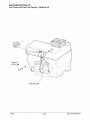
Engine and Carburetor
Fog engine with Polaris Fogging Oil (aerosol type)
according to directions on can. On models with carburetor
vacuum fittings the fogging oil can be sprayed through the
fitting.
If you choose not to use Polaris Fogging Oil perform the
following procedure: Support front of snowmobile so
engine is level or tilted slightly rearward. Remove spark
plug(s). Rotate piston to BDC and pour approximately two
ounces (16 ml) Polaris 2-Cycle Injector oil into the cylinder.
NOTE: Allow ample time for oil to flow from top of piston
down transfer ports and onto crankshaft bearings before
proceeding to next cylinder. Turn engine over several
times to insure coverage of piston rings, cylinder walls and
crankshaft bearings. See photo at right.
I.
1
I·
Polaris Fogging Oil PN 2870791
Carbon Clean PN 2871326
Treat the fuel system with Polaris Carbon Clean.
If Polaris fuel system additive is not used, fuel tank, fuel
lines, and carburetor should be completely drained of gasoline. To eliminate any fuel remaining in the carburetor,
run the engine until it stops.
Battery
Disconnect and remove battery. Fill with distilled water. Clean terminals and cables. Apply dielectric grease.
Charge until specific gravity is t least 1.270 (each cell). If machine is to be stored for one month or longer, fill and
charge battery monthly using Polaris Battery Tender, or a 1 amp trickle charger to maintain at 1.270 specific gravity.
··Polaris Battery Tender
PN 2871076
Exhaust System
At approximately 2000 miles, or in preparation of off season storage, it is a good idea to check the exhaust system
for wear or damage. To inspect, allow the engine and exhaust system to cool completely. Open the hood and
inspect the muffler and pipes for cracks or damage. Check for weak or missing retaining springs or damper/support grommets.
A
WARNING
Exhaust system temperatures can exceed 900° F (500° C). Serious burns may occur if this inspection is performed without allowing adequate time for the exhaust system to cool. Never perform this procedure with the
engine running.
Polaris Industries Inc.
2.31
10/98
MAINTENANCEfTUNE UP
Variable Exhaust System
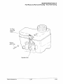
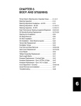
Variable Exhaust System (V.E.S.)
Some snowmobiles are equipped with the Polaris (patent pending) Variable Exhaust System (V.E.S.)
This unique exhaust valve management system changes the effective exhaust port height in the cylinder to provide maximum horsepower at high RPM without sacrificing fuel economy and engine torque at low to midrange
throttle settings .
.-----------------------------------------------------,
LOW RPM POSIT!ON7
Piston
Housing
Exhaust Valve
EXHAUST
PORT
Fig. 1
CYLINDER
*This is a representation only. Your model may differ.
In order to understand the operation and function of the V.E.S. we must first consider the characteristics of a two
stroke engine. The height of the exhaust port in a two stroke engine cylinder has an affect on the total power output
of an engine, as well as the RPM at which the power occurs.
Exhaust systems are ''tuned" by design to match engine exhaust port configuration and desired power delivery characteristics. Engines with relatively "high" exhaust ports (and exhaust pipe to match) produce more horsepower at high
RPM, but only at the expense of low to midrange fuel economy and torque. On the other hand, "low" port engines
provide good fuel economy in the midrange and make their power at relatively lower RPM, but will not produce as
much peak horsepower for a given displacement range. In general, an engine designed for a racing or high performance snowmobile will have a relatively high exhaust port compared to an engine of the same displacement range
designed for touring.
Although the V.E.S. does not in ttself increase horsepower, tt does allow an engine to be designed for maximum horsepower
without the inherent disadvantages of a high exhaust port.
The main components of the V.E.S. are the exhaust valve, valve housing, bellows, piston, return spring, and cover.
A guillotine style exhaust valve is connected to a moveable piston. This piston is attached to a flexible bellows, forming
two chambers. The lower chamber is connected to the cylinder by a drilled passageway located just above the exhaust
port. The upper chamber is vented to atmospheric pressure. A valve return spring is located in the upper chamber
between the piston and cover.
At idle and low speeds, the exhaust valve is held in the "low port" position by the return spring. When throttle is applied
(and RPM begins to increase) rising cylinder pressure is applied to the under side of the bellows via the actuation port.
This forces the exhaust valve upward against spring pressure. The valve continues to move upward toward the "High
Port" position as cylinder pressure, horsepower, and RPM increase.
10/98
2.32
Polaris Industries Inc.
MAINTENANCE!TUNE UP
Variable Exhaust System
440 XCR
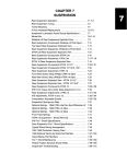
V.E.S. Maintenance
Due to the simplicity of V.E.S. design, maintenance is limited to a periodic inspection and cleaning of system components. The V.E.S. should be disassembled, inspected, and cleaned (remove carbon deposits) every 1000 to 2000
miles, depending on operating conditions. To ensure maximum performance and minimize required maintenance,
Polaris recommends the use of Premium Gold Synthetic 2 Cycle lubricant (PN 2871721) only. The use of other lubricants may cause improper function of the valve mechanism, and increase the frequency of required cleaning due to
excessive buildup of carbon deposits.
NOTE: To ensure maximum performance and minimize required maintenance, break in the engine using Polaris
TC-W3 oil (premix and injection tank) and then switch to Polaris Premium Gold Synthetic 2 cycle lubricant.
V.E.S. Removal and Cleaning
For VES removal and cleaning, refer to 440/500 Domestic Case Reed Twin and 700/800 XCR section in chapter
3, Engines.
Adjuster nut ~
0-ring
•
cover-~~
Spring
~
Valve cap ~;.
7" \
Bellows~~/'
Bolt
Valve
Washer~~/
"'-~,Valve
.
4
.&
~
Dowel pin
Gasket
\il
Polaris Industries Inc.
housing
Valve
700/800 XCR
2.33
10/98
MAINTENANCE!TUNE UP
Variable Exhaust System
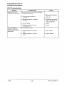
V.E.S. Troubleshooting
Symptom
Engine will not reach
designed operating RPM
Possible Cause
1. Exhaust valve sticking
2. Cylinder pressure feed port
restricted
Poor acceleration;
hesitation; High RPM
performance is normal or
near normal
10/98
Remedy
Valve not opening or not opening completely:
1. Remove carbon deposits,
burrs etc.
2. Clean port
3. Bellows damaged or not sealing
correctly
3. Inspect bellows, fastener
straps, and gasket and
repair as required
4. Incorrect spring
4. Inspect
5. Problem in clutch setup, drive
line, engine, etc.
5. Inspect
Valve opening too early:
1. Valve sticking open or partially
open
1. Clean, Inspect
2. Broken, damaged, or incorrect,
spring
2. Inspect, Replace
2.34
Polaris Industries Inc.
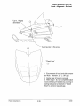
MAINTENANCE/TUNE UP
Hood - Alignment - Evolved
Up to .10" gap
allowable
.25"
±
.06"
Avoid pucker in this area.
"Cheek Area"
1. Ensure front of hood and side bumper
are flush. Maintain .25" ± .06" gap.
2. Center rear of hood to console.
3. After steps 1 & 2 are complete, adjust
hood overhang (if needed) by pushing or
pulling side panel at bracket in "Cheek
Area" to achieve required gap.
Polaris Industries Inc.
2.35
10/98
MAINTENANCE!TUNE UP
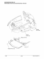
Side Bumper, Panel and Console Mounting - Evolved
·r(~ --------
~~
11 /"
~
~
Torque
4-6 in. lbs.
Torque
4-6 in. lbs.
Torque
4-6 in. lbs.
Torque 6 ft. lbs.
Torque 4-6 in. lbs.
10/98
2.36
Polaris Industries Inc.
MAINTENANCE/TUNE UP
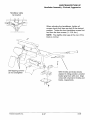
Handlebar Assembly - Evolved, Aggressive
Handlebar cable
tie location
When adjusting the handlebars, tighten all
screws evenly until bars are held in the desired
position. Torque the front handlebar screws first
and then the rear screws (11-13 ft. lbs.).
NOTE: The slightly wider gap at the rear of the
block is normal.
4'
a;=- :o-::=- ~~~
r
~I
~~
Self tapping screwsdo not overtighten
0
~
'
Polaris Industries Inc.
2.37
With throttle and brake blocks
aligned in riding position, position
heater grip flush with end. Align
wires with channel in throttle and
brake, respectively.
10/98
MAINTENANCE/TUNE UP
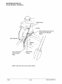
Routing Diagram - 340, 340 Deluxe, 340 Touring
Oil line
Push excess
vent line into
steering post
To fuel tank
To oil tank
10/98
2.38
Polaris Industries Inc.
MAINTENANCE/TUNE UP
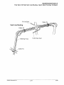
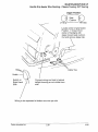
Oil Line Routing, 340 - 340 Touring
Recoil Rope Over the Top
of Wire Harness and Oil
Line
Oil Tank
Convoluted
Tubing
Oil Line
Toward
Outside
Polaris Industries Inc.
2.39
10/98
MAINTENANCEffUNE UP
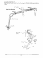
Oil Line Routing - 340 Deluxe
-Oil Tank
Wire Harness and Oil Line
Cable Tied to Bracket
Stand
Wire Harness
Oil Line Routed
Under Recoil
Ring
Convoluted
Tubing
NOTE: Be sure not to kink or pinch oil line.
10/98
2.40
Polaris Industries Inc.
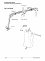
MAINTENANCE/TUNE UP
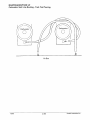
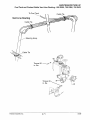
Fuel Tank I Oil Tank Vent Line Routing - Sport, Sport Touring, TranSport
Vent Line Routing
Steering Hoop
Polaris Industries Inc.
2.41
10/98
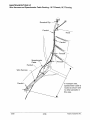
MAINTENANCE/TUNE UP
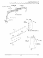
Fuel Pump and Fuel Line Routing - Sport, Sport Touring, TranSport
To Fuel
Shut-Off
Valve
---
Impulse Line
10/98
2.42
Polaris Industries Inc.
MAINTENANCE!TUNE UP
Fuel Tank/Oil Tank Vent Line Routing - XCF, Super Sport
Cable Tie
Vent Spring (3)
'\
Steering Hoop
Cable Tie (Panduit)
Polaris Industries Inc.
2.43
10/98
MAINTENANCEITUNE UP
Carburetor Vent Line Routing - Super Sport
Carburetor
0
t
i
Air Box
10/98
2.44
Polaris Industries Inc.
MAINTENANCE!TUNE UP
Fuel Tank/Oil Tank Vent Line Routing - Trail, Trail Touring
Cable Tie
Polaris Industries Inc.
2.45
10/98
MAINTENANCE/TUNE UP
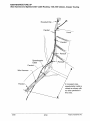
Wire Harness And Speedometer Cable Routing - Trail, Trail Touring
Speedometer
Cable
Panduit
Wire Harness
-
Panduit
10/98
In nosepan area,
speedometer cable is
routed as shown with
no other panduits in
this area.
2.46
Polaris Industries Inc.
MAINTENANCE/TUNE UP
Fuel Pump and Fuel Line Routing - Trail, Trail Touring
To Fuel
Shut-Off
Valve-------
Impulse Line
Polaris Industries Inc.
2.47
10/98
MAINTENANCE/TUNE UP
Carburetor Vent Line Routing - Trail, Trail Touring
Carburetor
0
t
i
Air Box
10/98
2.48
Polaris Industries Inc.
MAINTENANCEn"UNE UP
Fuel Tank/Oil Tank Vent Line Routing - 500, 500 Classic, Classic Touring
To Fuel Tank
Cable Tie
Vent Line Routing
Cable Tie
\
To Oil Tank Vent
Steering Hoop
Torque
4-6ft. lbs.
1
()
I
I
t;jl
~~~~~
J/l
8 em
®
8\m~~iJl'
~P
j\)J Coolant Bottle & Hose
·~~
V~/~
~
Oil Tank
8cm
Polaris Industries Inc.
2.49
10/98
MAINTENANCE!TUNE UP
Wire Harness and Speedometer Cable Routing - 500, 500 Classic, Classic Touring
Speedometer
Cable
Panduit
Wire Harness
-
In nosepan area,
speedometer cable is
routed as shown with
no other panduits in
this area.
10/98
2.50
Polaris Industries Inc.
MAINTENANCEfTUNE UP
Fuel Pump and Fuel Line Routing - 500, 500 Classic, Classic Touring
To Fuel
Shut-Off
Valve-----
Torque
4-6 in. lbs.
\
\~
Ii
I
)@/
; l
~j))Y
Impulse Line
Polaris Industries Inc.
2.51
10/98
MAINTENANCEfTUNE UP
Carburetor Vent Line Routing - 500, 500 Classic, Classic Touring
~
Air Box
+
..'
.
0
10/98
2.52
Polaris Industries Inc.
MAINTENANCE!TUNE UP
Cooling System - 500, 500 Classic, Classic Touring
Keep Away From Exhaust
Hats
Keep Hose From Looping Way
Out Into Nosepan
Polaris Industries Inc.
2.53
10/98
MAINTENANCE/TUNE UP
Fuel Pump and Fuel Line Routing - Widetrak LX
To Fuel
Shut-Off
Valve-----
Impulse Line
10/98
2.54
Polaris Industries Inc.
MAINTENANCE/TUNE UP
Cooling System- Widetrak LX
\
Secure to clamp
with tie strap
Maintain approx. 1/4"
gap between hose
and sway bar
Keep Hose From Looping Way
Out Into Nosepan
Polaris Industries Inc.
2.55
10/98
MAINTENANCE/TUNE UP
Fue Tank/Oil Tank Routing - Widetrak LX
ToFu I Tank
Vent Line Routing
Cable Tie
Steering Hoop
To Oil Tank Vent
Torque nut
4-6ft. lbs.
I
®--®---_
((
1
\
I
10/98
2.56
Polaris Industries Inc.
MAINTENANCEITUNE UP
Fuel Tank I Oil Tank Vent Line Routing- XLT Classic, XLT Touring, XLT Special
To Fuel Tank
Vent Line Routing
Cable Tie
Cable Tie
\
To Oil Tank Vent
Steering Hoop
Torque
4-6ft. lbs.
Oil Tank
26cm
Polaris Industries Inc.
2.57
10/98
MAINTENANCE/TUNE UP
Wire Harness and Speedometer Cable Routing- XLT Classic, XLT Touring
Rosebud Clip
Panduit
Panduit
Wire Harness
-
Panduit
10/98
In nosepan area,
speedometer cable is
routed as shown with
no other panduits in
this area.
2.58
Polaris Industries Inc.
MAINTENANCE/TUNE UP
Fuel Pump and Fuel Line Routing- XLT Classic, XLT Touring
Oil Line
Polaris Industries Inc.
2.59
10/98
MAINTENANCE/TUNE UP
Backrest- Classic Touring, XLT Touring
Leave cable on rear outside
portion of backrest adjuster
so it doesn't get pinched
when backrest is put down fr
on seat for shipping
u
/
7 - 9 ft. lbs.
/'@r(J
//
·@),:,
/
I /'.l:
/
/
/
. (./
!?>
\
1:0
I
37ft. lbs.
16 - 18 ft. lbs.
fl ...... /
16 - 18 ft. lbs.
10/98
2.60
Polaris Industries Inc.
MAINTENANCE!TUNE UP
Handle Grip Heater Wire Routing- Classic Touring, XLT Touring
Zipper Position
0
Seat
Cushion
0
\...__)
LH Grip L.....------~ RH Grip
Locate center of grip heater.
Position 1" forward from
center of handgrip with
zipper toward seat cushion.
Cut and remove zipper tab.
Switch
Switch on
Right Hand
Side
Connect wiring and tuck in behind
taillight housing so not visible from
side
Wiring to be separated at bottom one wire per slot
Polaris Industries Inc.
2.61
10/98
MAINTENANCEffUNE UP
Fuel Tank and Coolant Bottle Vent Line Routing, 440 XCR, 500 XC/SP, 600 XC/SP, 700
XC/SP
Cable Tie
Vent Line Routing
Steering Hoop
Torque 50
in. lbs.
10/98
~--®/
2.62
Polaris Industries Inc.
MAINTENANCE/TUNE UP
Fuel Tank and Coolant Bottle Vent Line Routing - 700 XCR, 800 XCR
Steering Hoop
-
·-
Torque nut
4-6ft. lbs.
·; fi
_I
',1~<5,
I \~
/~
Torque nut
4-6ft. lbs.
Polaris Industries Inc.
2.63
A
I
--~
~%
~~
~f!J
10/98
MAINTENANCE/TUNE UP
Fuel Tank/Oil Tank Vent Line Routing -Trail RMK
Cable Tie
Torque 50 ~--®
in. lbs.
Torque 40
in.lbs.
~-%
~~
10/98
2.64
Polaris Industries Inc.
MAINTENANCE/TUNE UP
ACCS System -Trail RMK
/To handlebars
~
Polaris Industries Inc.
2.65
10/98
MAINTENANCE!TUNE UP
Fuel Tank I Oil Tank Vent Line Routing - 500 RMK
To Fuel Tank
Cable Tie
Vent Line Routing
Cable Tie
\
/~-@._
Steering Hoop
Torque
4-6 ft. lbs.
-_- /
I
el
(()I
I
~~ ~~:
J../l
a em
®
p~lj
~P
~J Coolant Bottle & Hose
v~
~
Oil Tank
8cm
10/98
2.66
Polaris Industries Inc.
MAINTENANCE/TUNE UP
Wire Harness and Speedometer Cable Routing - 500 RMK
Panduit
Wire Harness
-
In nosepan area,
speedometer cable is
routed as shown with
no other panduits in
this area.
Polaris Industries Inc.
2.67
10/98
MAINTENANCE/TUNE UP
Cooling System - 500 RMK
Keep Away From Exhaust
Hats
Maintin Approx 1/4" Gap
Between Hose & Sway
Bar
Keep Hose From Looping Way
Out Into Nosepan
10/98
2.68
Polaris Industries Inc.
MAINTENANCE/TUNE UP
Fuel Pump and Fuel Line Routing- 500 RMK
To Fuel
Shut-Off
Valve-----
Torque
4-6 in. lbs.
~\~~r
~j)V
Impulse Line
Polaris Industries Inc.
2.69
10/98
MAINTENANCEfTUNE UP
ACCS System- 500 RMK
/To handlebars
/
/
Torquato~
4 to 6 in. lbs.
10/98
2.70
Polaris Industries Inc.
MAINTENANCE/TUNE UP
Fuel Tank and Coolant Bottle Vent Line Routing - 600 RMK, 700 RMK, 700 SKS
Vent Line Routing
Cable Tie
Steering Hoop
Torque 50 --~J~"~~
in. lbs.
Polaris Industries Inc.
2.71
10/98