1
Lotus Service Notes
Section CI
CI.1 - GENERAL DESCRIPTION
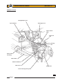
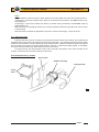
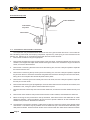
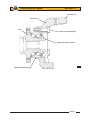
The fully independent front suspension comprises, on each side of the car, upper and lower wishbones, a
concentric coil spring/telescopic damper unit, and a tubular anti-roll bar. A forged steel hub carrier, provides a
mounting for a the hub bearing unit to which the road wheel is attached via four spline socket bolts.
The upper and lower 'A' frame wishbones are fabricated from steel tube, the upper wishone braced by
sheet steel gussets at its apex, and the lower wishbone braced by a tubular strut at its base. The inboard ends
of both wishbones use replaceable bonded rubber pivot bushes to provide maintenance free articulation, with
a specification providing accurate and responsive dynamic characteristics. The outer ends of both wishbones
incorporate housings into which the upper and lower steering swivel ball joints are pressed. The upper ball
pin is secured to the forged steel, rearward facing steering arm, itself fixed to the hub carrier by two M10 bolts.
The ball pin of the lower swivel joint is secured directly into a tapered hole in the bottom of the forged steel hub
carrier. The Bilstein spring/damper unit acts between the outer end of the lower wishbone and the chassis,
and is fitted with the damper rod lowermost in order to minimise unsprung weight.
A forward mounted tubular steel anti-roll bar, is supported in chassis mounted rubber pivot bushes and is
operated via short ball jointed drop links from the lower wishbones.
CI.2 - GEOMETRY & ADJUSTMENTS
Provision is made for the adjustment of wheel alignment, camber and castor. Under normal service conditions, no periodic scheduled check of the geometry is necessary, although a front wheel alignment check is
recommended when the front tyres are replaced. A full geometry check is required only after front suspension
repair, or if excessive tyre wear is evident, or if steering difficulties are encountered. Before any measurements
or adjustments are made it is essential first to set the vehicle to its ‘mid-laden’ ride height, approximating to
driver and passenger and a half tank of fuel. This will require the vehicle to be ballasted, or tied down:
Standard Elise
Mid-laden ride height (reference height for geometry check);
- front
130 mm below front end of chassis siderail
- rear
130 mm below rear end of chassis siderail
Camber
- optimum
- 0.1°
- tolerance
+ 0.1° to - 0.3°; Max side/side 0.2°
Castor
- optimum
+ 3.8°
- tolerance
+ 3.5° to + 4.1°; max. side/side: 0.35°
Alignment
- optimum
Zero
- tolerance
0.5 mm toe-out to 0.7 mm toe-in overall
(0.07° toe-out to 0.10° toe-in overall)
Steering axis inclination
12° nominal
Roadsport Elise, Exige
Mid-laden ride height (reference height for geometry check);
- front
130mm below front end of chassis siderail
- rear
130mm below rear end of chassis siderail
Camber
- optimum
- 0.3°
- tolerance
- 0.1° to - 0.5°; max. side/side: 0.2°
Castor
- optimum
+ 3.8°
- tolerance
+ 3.5° to + 4.1°; max. side/side: 0.35°
Alignment
- optimum
Zero
- tolerance
0.5 mm toe-out to 0.5 mm toe-in overall
(0.07° toe-out to 0.07° toe-in overall)
Steering axis inclination
12° nominal
Page 3