1
Lotus Service Notes
Section CI
(A082C6042V) to ease fitment, and assemble as follows:
Top wishbone - insert from the outside of both pivot eyes (from front of front eye, and rear of rear eye).
Lower wishbone - insert from the inside of both pivot eyes (from rear of front eye, and front of rear eye).
Note that all top wishbone pivot bushes are common with the exception of the top wishbone rear pivot,
which contains no interleaf sleeve and is identified by a blue paint mark.
11.
Top and bottom swivel joints are identical, and may be replaced if necessary using a suitable press.
12.
If the anti-roll bar is to be removed; remove the front alloy undertray, and, by drilling out the rivets, the
small alloy closing panel at each side of the crash structure below the anti-roll bar. Release the a.r. bar
clamps and drop links, and withdraw the bar.
13.
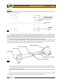
The road spring may be removed from the damper using a suitable spring compressor to allow the spring
lower slotted seat to be withdrawn. Note that spring upper seat is located by a square section circlip on
the damper body:
- Standard Elise: Use centre of 3 grooves for mid-laden ride height of 130mm.
- USA Elise: Use lower of 3 grooves for mid-laden ride height of 135mm.
- Elise with Roadsports suspension package and non-USA Exige: Use the upper of 2 grooves for midladen ride height of 130mm.
14.
To remove the hub bearing unit from the hub carrier, release the three Torx head bolts and withdraw the
complete unit. The hub unit is not serviceable, and is replaced complete if faulty.
Reassembly
Re-assemble the suspension in reverse order to disassembly with the following notes:
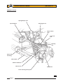
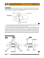
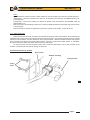
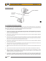
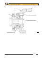
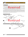
Take care to assemble each pivot bolt with the correct washers/snubbers/spacers as shown in the diagrams.
Smear the shank of each pivot bolt with PBC grease, but do not allow contamination of the threads.
Take care to refit the original camber adjustment shimpack, and distribute the castor shims as noted on
removal.
Top ball joint plinth fixing bolts:
The bolts securing the steering arm/top ball joint plinth to the hub carrier were upgraded in March '04 at
VIN serial number 1537 (approx.) in order to commonise with motorsport applications. Earlier type 8.8
grade bolts should be tightened to 45 Nm; Later 10.9 grade bolts to 68 Nm. The bolt grade is stamped
around the head of the bolt. The thread of both bolt types should first be treated with Permabond A130
(A912E7033V).
After re-fitting a standard anti-roll bar, ensure that the crash structure closing panels are re-rivetted.
Lubricate the rubber type anti-roll bar mountings with rubber grease and the Nylon type with MoS2
grease.
Apply Permabond A130 (A912E7033V) to the threads of the steering arm bolts.
Lubricate the ends of the damper top eye bush with rubber grease.
Press the brake pedal to reposition the pads before driving the car.
If the car suffers a suspension impact sufficient to damage a wheel rim, careful attention should be paid to
all related suspension components. Such forces can cause stretching of the lower ball pin and consequent
fixing nut torque loss. As a safety precaution, it is recommended that in all such cases, the lower ball joint
and the two bolts securing the upper ball joint plinth to the hub carrier are renewed.
The Service Schedule specifies that the security of the front and rear suspension is checked at each service.
For cars used on race tracks, or in similar conditions, suspension components and torque checks should be
carried out between sessions. This operation requires that all the principal suspension pivot bolts are torque
checked, noting the following points:
Where a bolt is tapped into a housing or weldnut, and relies on a thread locking compound for security, it
is important to appreciate that if the bolt is disturbed, the locking compound must be re-applied. The following
procedure should be adopted for all such fixings:
Check the torque of the fixing.
If the specified torque is attained without the fixing being disturbed (moving), take no further action.
If the bolt moves, the locking action of the thread adhesive will have been compromised. Remove the
Page 9