1
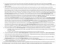
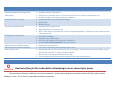
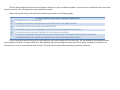
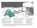
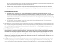
Service Manual
Kerr KP-3300HP Plunger Pump
Kerr Pump Corporation
Post Office Box 735 2214 West 14th Street
Sulphur, Oklahoma 73086
Phone: 580-622-4207 Fax: 580-622-4206
Website-www.kerrpumps.com
[email protected]
United States and Canada
800-441-8149
KERR PUMP CORPORATION SERVICE MANUAL EIGHTEENTH EDITION NEW PUMP WARRANTY A. Kerr Machine Co. (Kerr Pump Corporation) warrants its new pumps to be free from defective materials and/or workmanship for a period of one year from the date of sale by the Distributor, provided that the new pump is registered in accordance with Paragraph No. 2 hereof, properly installed and operated in accordance with the Company’s Service Manual, and all other terms of this warranty agreement are complied with by the purchaser. As hereinafter provided, this warranty includes the replacement of parts and labor to correct any deficiency. All defective parts must be returned to the Company’s Home Office for examination before this warranty is effective. This warranty applies to parts, which have been replaced under this warranty only so long as the original pump warranty is effective. This warranty is for the exclusive benefit of the purchaser and is not transferable. B. Each Distributor of a new pump will provide the customer with a registration blank furnished to him by the Company which must state the date of sale, be signed by the purchaser and the Distributor, and delivered to the Home Office of the Company within fifteen (15) days of the date of sale. C. In the event of a claim under this warranty, made within the one‐year warranty period, the purchaser must notify the Distributor, and the Distributor shall contact Kerr Pump Corporation before any repairs or service calls are made. D. All warranty claims must be sent to Kerr Pump Corporation Home Office on the authorized warranty claim form provided by Kerr Pump Corporation, and available from the Distributor before any warranty claim will be considered. It is understood that Kerr Pump Corporation will deteriorate due to ordinary wear, therefore, the following credits shall apply to all replacement parts, labor, surface freight, travel time and mileage allowance furnished under this warranty. i. For the first ninety (90) days from the date of sale by the Distributor, 100% credit will be allowed on a current list price basis. ii. From 91 to 180 days from the date of sale by the Distributor, 75% credit will be allowed on a current list price basis. iii. From 181 days to 270 days by the Distributor, 50% credit will be allowed on a current list price basis. iv.
From 271 days to one year after the date of sale by the Distributor, 25% credit will be allowed on a current list price basis. The credit given to the Distributor for replacement parts or pumps under this warranty is based upon the Distributor’s net cost paid Kerr Pumps for such replacement parts or pumps. E. In the event of a warranty claim under this warranty made within ninety (90) days of the date of sale by the Distributor, Kerr Pump Corporation, before any repairs are made, shall be contacted by the Distributor and given the option of having the Distributor either repair or replace the pump. F. Upon any claim under this warranty, other than a claim wherein Kerr Pump Corporation at its option replaced the pump as provided in Paragraph No. 5 hereof, the Distributor will make the necessary repairs an/or replacement, and Kerr Pump Corporation shall allow the cost of labor on warranty claims. The labor cost may include travel time not to exceed (8) hours of actual travel time. Kerr Pump Corporation will pay surface freight on warranty shipments. After making the necessary repairs and/or replacements, the Distributor will bill the customer for the full amount due for the repair. Thereafter, the Distributor will submit the warranty claim form provided by Kerr Pump Corporation to the Kerr Pump Corporation Home Office for consideration. In the event the warranty claim is honored by Kerr Pump Corporation a Credit Memorandum will be issued to the Distributor in the amount determined by the table in Paragraph No. 4 hereof. Thereafter, the customer’s invoice will be credited by the Distributor in the same percentage allowed the Distributor by Kerr Pump Corporation. If requested by Kerr Pump Corporation the purchaser or the Distributor shall return the alleged defective product to Kerr Pump Corporation factory, freight prepaid, for examination and testing. If Kerr Pump Corporation determines the product is defective Kerr Pump Corporation will either repair or replace such product with a like of Kerr Pump Corporation manufacture, f.o.b. to the Distributor or allow the Distributor credit to an amount equal to the invoiced value of the defective product. The responsibility of Kerr Pump Corporation is limited to the repairing or replacing defective material manufactured by it, provided Kerr Pump Corporation examination discloses to its satisfaction that such material has not been altered or repaired, other than by Kerr Pump Corporation approved procedures, subject to misuse, improper maintenance, negligence or accident. Kerr Pump Corporation will not be responsible for loss of liquid or for damage of any kind, or from any cause, to any person or property of any person, or for loss of revenue of profit, or for any other special incidental or consequential damages. G. The warranty applies only to new Kerr Pump Corporation. The Company specifically excludes from this warranty the following. i. All plungers, valves, plunger packing, valve springs, seals gaskets, and corrosion and/or erosion damage caused by the fluid handled by the Company’s pump. ii. In addition, after the expiration of the pump warranty all replacement parts are no longer in warranty. H. In extreme cases where in the opinion of Kerr Pump Corporation, if a pump has been misused or is being misused, Kerr Pump Corporation reserves the option to offer to redeem the pump from the purchaser. Should the purchaser refuse to allow the pump to be redeemed and chooses to continue improper operation, the warranty will be void. I. Any parts or equipment which Kerr Pump Corporation supplies and does not manufacture shall be subject only to the warranties of Kerr Pump Corporation vendors to the extent Kerr Pump Corporation can enforce such warranties. J. Any repairs to, alterations of, or work done on alleged defective products without Kerr Pump Corporation specific written authorization shall void Kerr Pump Corporation warranty applicable thereto. K. Any action for breach of warranty or other action under this agreement must be commenced within (1) year after such cause of action arises. This limited warranty is in lieu of all other warranties, expressed or implied, including any implied warranty or merchantability or fitness. TROUBLESHOOTING GUIDE Problem Unusual pounding, knocking broken valve spring Loss of pressure or volume Consistent, rhythmic knock Packing failure (Excessive) Abnormal wear of fluid end parts Abnormal wear of power end parts Heat in power end Reason/Solution •
•
•
•
•
•
•
•
•
•
•
•
•
•
•
•
•
•
Insufficient fluid at high speed. Suction line is improper size or is constricted. (Trash in line, valve partly opened, etc.) Possibility of gas in the fluid causing the roughness. Foreign matter may be holding valves open. Worn valves. Broken springs. Improper bearing adjustment. Worn bearings or connecting rods. NOTE: Valve noise is common and normal in high‐speed pumps. It should not cause concern unless it becomes erratic. Improper installation. Improper type of lubrication. Incorrect type of packing for particular installation. (Contact Kerr Pump Corporation if you are unsure.) Abrasive or corrosive fluid. Lack of oil, overload on pump, foreign matter in oil. A new pump will run hot for a short period (2 or 3 days). See above for persistent heating. Pump will operate near 140˚ F. under average conditions. Check for air in pump by bleeding at cover caps. Too much spring tension Reciprocating pumps have very limited pick up. INSTALLATION INSTRUCTIONS WARNING Read everything in this section before attempting to run or connect your pump. The importance of proper installation cannot be overstressed. As the reciprocating pump is almost unable to lift fluid, proper suction flooding is a must. This is the First step toward satisfactory operation. The Kerr Pumps Engineering Service will be happy to advise you in your installation problems. As almost every installation varies, you cannot exercise too much care in making certain your installation is proper. Before Starting The Pump, read carefully the maintenance section in the following pages. For best results, follow these installation guidelines. (A) PRESSURE RELIEF VALVE (REQUIRED) (B) BY‐PASSED FLUID SHOULD BE PIPED BACK IN SUCTION SUPPLY TANK WHEN POSSIBLE (C) (D) (E) (F) USE FLEXIBLE HOSE IN DISCHARGE LINE WHEN POSSIBLE DISCHARGE SHUT‐OFF VALVE (OPTIONAL‐USED FOR TOTAL SHUT‐DOWN OR SERVICE ONLY) DISCHARGE AND SUCTION ON EITHER SIDE OF FLUID END ON ALL MODELS. PULSATION “DAMPENERS” MAY BE USED IN EITHER THE SUCTION OR DISCHARGE PIPING OR BOTH. DISCHARGE DAMPENERS SHOULD BE CAPABLE OF HANDLING PUMP DISCHARGE MAXIMUM PRESSURE To start the pump, open the suction line valve and permit the intake chamber to fill on the pump. Air may be bled off by opening the valve covers slightly until there is a constant fluid flow. After bleeding, open the discharge line valve and start the pump. Roughness may occur from cavitation (air in line) or from starvation (lack of fluid). Eliminate these troubles before permitting continuous operation. 1)
2)
3)
4)
CENTERLINE OF PUMP SUCTION (INLET) TO BE SLIGHTLY
HIGHER THAN CENTERLINE OF SUCTION (INLET) VALVE - SO
ANY AIR IN SUCTION SYSTEM PROMPTLY REACHES PUMP
AND IS EXPELLED
SLOPE BYPASS LINE SO LOW POINT DRAIN WILL FULLY
EMPTYRELIEF AND CHOKE VALVES AND ALL LIQUID IN
BYPASS CIRCUIT
DO NOT LOCATE PIPING OR OTHER EQUIPMENT IN FRONT
OF OR ABOVE PUMP FLIUD END PREVENTING SERVICING –
REFER TO MANUFACTURER FOR MINIMUM CLEARANCES
LOCATE CHARGING PUMP AT POINT SHOWN. – IF
CHARGING PUMP IS NECESSARY (FOR VOLATILE FLUIDS,
FOR EXAMPLE)
5)
6)
7)
8)
IF DESIRED, A TWO-WAY MOTOR OPERATED BYPASS VALVE MAY
BE USED RATHER THAN MANUAL TYPE – IT SHOULD BE DESIGN TO
OPEN AUOMATICALLY WHILE STARTING OR STOPPING
BYPASS LINE SHOULD FEED LIQUID INTO TANK BELOW MINIMUM
LIQUID LEVEL
TO REMOVE PIPING STRAIN AND VIBRATION A FLEXIBLE HOSE,
EXPANSION JOINT OR SWIVLE JOINT PAIR SHOULD BE
POSITIONED TO MINIMIZE EFFECTS OF PIPING THERMAL
EXPANSION, CONTRACTION AND PIPING WEIGHT
SUCTION SIZED FOR 1 ½ TO 2 FT/SEC MAX FLOW RATE.
DISCHARGED SIZED FOR 8 TO 10 FT/SEC MAX FLOW RATE –
SUCTION AND DISCHARGE MUST BE SUPPORTED AND
ANCHORED
9)
TO PROTECT SUCTION SYSTEM AGAINST
HAZARD OF DISCHARGE PRESSURE ENTRY
(AS WHEN PUMP IS IDLE), A SMALL RELIEF
VALVE IS OFTEN CONNECTED HERE
10) ALL SYSTEM COMPONENTS MUST HAVE
ADEQUATE PRESSURE RATINGS FOR
OPERATING, STARTING AND UPSET
CONDITIONS. IN ORDER TO REDUCE
POTENTIAL HAZARDS, PARTICULAR
ATTENTION IS RECOMMENDED FOR THE
SURGE CONDITION THAT WILL RESULT
DOWNSTREAM OF THE REFLIEF VALVE
WHEN NORMAL DISCHARGE IS BLOCKED
-AS A GENERAL RULE, FLUID LEVEL MUST BE HIGHER THAN THE PUMP FLUID END AS PLUNGERS CANNOT LIFT FLUID. 10 FEET OF HEAD IS A GOOD RULE OF THUMB.
-CAUTION SHOULD BE TAKEN TO KEEP FITTINGS OUT OF THE SUCTION AND DISCHARGE PIPING AS THESE WILL RESULT IN POOR PERFORMANCE. EACH 90-DEGREE TURN IN
THESE LINES RESULTS IN GREAT LOSS OF PUMPING EFFICIENCY.
PREVENTIVE MAINTENANCE DAILY A. Check and Maintain Lubricant Levels. Standard Lubricant: Synthetic Lubricant: AGMA Grade (ASTM D 2422): 4 EP SAE Viscosity Grade (J306‐8): 75W‐90 ISO Viscosity Grade: 150 Viscosity in SSU @ 100 degree F: 625‐765 MONTHLY A.
B.
C.
D.
E.
F.
G.
Drain and refill crankcase. It is recommended that oil be changed after the first week of operation. Wash oil filler cap in kerosene. Check valves for excessive wear, broken or bent springs, etc. Check crankshaft bearings for endplay. (See section on crankshaft) Keep all nuts, studs, etc. tight. Check valve covers for leaks. Check all seals and gaskets for leaks PUMP CAPACITIES (APPROXIMATE) KD‐1250 2 qts. KT‐3350 KJ‐2250 KZ‐3150 3 qts. KT‐3400 16 qts. 2 qts. Use SAE 30 weight non‐detergent motor oil ONLY KM‐3250 4 qts. KB‐3500 20 qts. KM‐3300 4 qts. KA‐3500 36 qts. KP‐3300 R335/R340 12 qts. 16 qts. KSB‐6400 KSB‐6500 36 qts. 36 qts. Q5450 22.5 gal. KCP‐6300 24 qts. 16 qts. PLANETARY GEAR REDUCERS #6 17 ozs. #8 42 ozs. #9 42 ozs. B. If pump has lubricating facilities for stuffing boxes, check level of lubricant. C. Maintain packing gland tension on packing (Do not over‐tighten) D. Visually inspect pump for apparent trouble. E. Keep the pump clean. GENERAL Replace any work part before its eventual failure. Use the following instructions for removal and replacement of parts. Don’t hesitate to call on Kerr Pumps for help if necessary. SERVICE PROCEDURES (ALL MODELS) A. WING GUIDED VALVES i.
DISCHARGE VALVES: The discharge valve and seat can be exposed by first removing the discharge valve cover cap. Once the discharge cover cap has been removed you may lift out the discharge valve spring and the discharge valve. The valve seat will be held in place by a taper fit and must be “pulled” with an appropriate valve‐pulling tool (available from the Kerr Pumps Dealers). Once the valve and seat have been removed they should be resurfaced or replaced if badly worn. To replace the discharge valve, first clean and inspect the seat bore for washout defects and then drop the seat into the bore. Replace the valve into the seat and strike the top of the valve a couple of good blows utilizing a brass bar and hammer to seat the valve seat in the fluid end valve bore. Replace the valve spring and cover cap after inspecting the spring and the seal of the cover cap. ii.
SUCTION VALVES: The suction valves are located in the chamber directly below the suction or end valve cover caps. The suction valves are serviced in the identical manner as the discharge valves. Note: Discharge valves must be removed prior to any removal of the suction valves. Service Procedure for KZ‐3150 Valves iii.
DISCHARGE VALVES: The discharge valve and seat can be exposed by first removing the discharge valve cover plate. Once the discharge cover cap has been removed you may lift out the discharge valve spring, discharge valve and valve seat. Once the valve and seat have been removed they should be replaced if badly worn. To replace discharge valve, first clean and inspect the seat bore for wash out defects and then drop the seat into the bore. Replace valve in seat then valve spring and cover cap, always‐inspecting o’ring seals between seats and cover caps. iv.
SUCTION VALVES: The suction valves are located in the chamber directly below the discharge valve seat. The suction valves are serviced in the identical manner as the discharge valves. B. DISC TYPE VALVES: All disc‐type valves are exposed for removal in a similar manner as the wing‐guided valves. Instead of removing the valve body; the upper portion of the valve is removed by removal of the valve capscrew, spring retainer, valve spring, and valve spacer sleeve. The valve seat is then “pulled” from the fluid‐end utilizing an authorized Kerr Valve Puller. Note: In all Kerr Pumps with disc‐type valves the discharge and suction valves are identical. C. BALL AND SEAT VALVES: In pumps with block/billet type fluid‐ends the valves are ball and seat design. These are exposed for removal/inspection by removal of the appropriate valve cover. The flat seats are kept in place by a screw‐in valve retainer that can be best removed with a Kerr Valve Wrench made for the appropriate pump. Springs are normally incorporated with the discharge valves while the suction valves operate with a “free ball”. A copper washer/gasket is used under all valve seats for a seal. When installing or removing a flat type valve seat a good “rap” on top of the valve wrench will “seat/unseat” the seat and copper gasket prior final tightening or removal. Failure to “seat” the valve seat in this manner can result in the “washing out” of the fluid‐end. For pressurized suction, valves will need to be spring loaded. Call Kerr Pumps for this change. D. PLUNGERS: Following the removal of the suction valve, the plunger may be removed by breaking the union between the plunger and pony rod and forcing the plunger out the back of the fluid‐end. Loosening the packing nut/gland will facilitate the removal of the plunger. The reverse of this procedure is used to install a plunger. Lubrication and some slight force may be used to pass plunger through the packing. Always retighten the plunger and pony rod union periodically following the removal of the plunger to insure it is securely made up and will not vibrate loose. E. PLUNGER PACKING: This manual includes illustrations of the packing sets for each model pump. Generally, once the plunger has been removed from the pump, the packing can be exposed for removal by completely removing whatever device is used to tighten the packing (i.e. the packing or stuffing box nut or gland). There will be various amounts of metal rings and packing components depending upon the type of packing and the model of pump (refer to appropriate illustration or chart). After the removal of all rings and equipment from the stuffing box; thoroughly clean it and inspect for damage, which might keep the new packing from working properly. If the stuffing box is in satisfactory condition, install the new packing as per the appropriate illustration. It is a good idea to lubricate new packing with a light oil prior to installation. Most of the standard packing used in pumps should be tightened with the original equipment‐packing wrench while the pump is running under normal operating pressure. After a two or three hour run‐in, check the packing for tightness and re‐adjust as necessary. Packing should be checked for tightness on a periodic basis, but it is not a good idea to attempt to periodically tighten the packing as part of routine maintenance. This tends to “wear out” the packing prematurely. When the packing leaks in an excessive amount it should be replaced. There is no value in constantly “re‐tightening” leaking packing. If your pump is equipped with optional “spring loaded” packing, there is no adjustment in this equipment during its operational life. The stuffing box nut is initially tightened as much as possible and there is no further adjustment. Note: In all cases the spring goes in the stuffing box before the packing rings. When using the optional Kevlar or Teflon packing, be sure to rotate the “splits” so that none are “aligned” to insure that the packing holds properly. Normally, this packing is not lubricated and requires less tension on the stuffing box nut during operation. CAUTION: An “airtight” seal is not desirable with this plunger packing. Some slight dripage is desirable during operation. Attempts to tighten packing until it completely “seals off” will result in premature failure from too much friction. The Kevlar & Teflon packing must be allowed to drip a small amount to assure normal life. F. PONY ROD and PONY ROD PACKING: Kerr Pumps use two pony rod sealing arrangements, models KD‐1250, KJ‐2250, KM‐3250 and KCP‐6300 use a screw in seal gland, all other models use a bolt in seal gland, these glands use press in oil seals with snap ring retainers. Some Bolt in gland use adjustable packing arrangements with bolt in or screw in followers to adjust packing. By unscrewing plunger from pony rod a gap may be facilitated to allow the removal of the various sealing arrangements. A special wrench will be needed to remove and replace pony rod to crosshead. (This wrench is available from Kerr Dealers) All pony rods have a jam nut to align tighten pony rod to crosshead, care must be exercised in installing new seal on pony rod not to damage it. G. DISASSEMBLY OF POWER END CAUTION: Prior to disassembly of any power end, the plunger, pony rod, and pony rod seal housing must be removed. Expose the crankshaft and connecting rods by removing the pan cover. Connecting rod caps may now be removed and the connecting rod and crosshead should be shoved all the way to the rear (toward the fluid end) to facilitate crankshaft removal out either side as convenient. The connecting rods and crossheads may now be taken out the front cavity exposed by removing the crankshaft. Connecting rods may be removed from the crosshead by loosening the setscrew and driving out the wrist pin from the crosshead. A bronze bushing is used in the rod it may be driven out of the rod and replaced with a new bushing. Reassembly is the reverse of the above outlined sequence with the following considerations for “fits” or tolerance: i.
General: All Kerr components are machined on modern production machine tools and are of the same specifications and close tolerances you would expect in a modern automobile engine. It must be pointed out that at top speed (350 to 400 RPM) your pump will not even be approaching idle speed for a gasoline engine so “field fits” are possible and practical when making repairs and replacements away from the factory. All procedures outlined below are possible with only hand tools and absolutely no instruments, special tools, or gauges are needed. ii.
Connecting rod and wrist pin: Proper fit will find the wrist pin turning freely in its bore in the connecting rod, but it should have no “wobble” that is discernable up and down the main axis of the connecting rod. This looseness in the wrist pin fit is the most probable cause of “knocking” which is traceable to the power end of most all pumps. The only solution for loose fitting wrist pins is to discard the connecting rod wrist pin bushing and replace with a new one. If any wear is visible on the wrist pin it should always be replaced. iii.
Crankshaft End Play and Lateral adjustments: Adjustment of the Taper Roller bearings used in all Kerr Pumps is accomplished by removing or adding shims under the bearing housing. Shims are taken out or added until the crankshaft (without connecting rods) will turn freely, but with no endplay felt when attempting to pull or push the jackshaft end of the crankshaft along its long axis. Some lateral adjustment is possible by removing shims from one side of the crankshaft and adding them to the opposite side. (Note: Lateral adjustment is the “centering” of the crankshaft in the power frame housing.) iv.
Connecting Rod to Crankshaft fitting: Factory bored connecting rods will normally fit the standard crankshaft journal just by bolting the cap on the rod with the standard rod shims being used. If the caps do require adjustment this is accomplished by removing or adding various thicknesses of rod shims. The standard connecting rod shim used on all Kerr Pumps is 1/32” thick and is comprised of .002” laminates, which can be “pealed “ off separately. Proper fit of the connecting rod will allow the pump crankshaft to be rotated while not allowing in‐and‐out slack in the connecting rod along its long or main axis. A well‐fitted rod will have none of the in‐and‐out slack, but should be free enough to be moved from side to side on the rod journal. This insures the rod not being too tight. A point of caution when installing the connecting rod assembly in the pump is to make certain the oil holes in the rod are “UP” and not toward the bottom of the pump. This will result in lubrication failure in these parts and the pump will fail in a short period of time. An additionally important step is to make sure that the rod cap is bolted back on the rod as it came off. The rod and cap carry a “mark” or “number” which allows you to match them back properly. Failure to do this will cause the rod not to fit the journal for which it was made. H. Power End/Fluid End Connection: A common misconception is that there is some form of fluid seal between the power end and the fluid end. This is false. The fluid end is merely bolted to the power frame. It can be removed by breaking the plunger connection, backing off the packing nut or gland, removing the various fluid end bolts, and sliding the entire fluid end off the power frame. Corrosion may tend to seize the two components together making their separation difficult in some isolated cases. On models KP‐3300, KT‐3350/KT‐3400 and R335/R340 the bolted in stuffing box assemblies must be removed prior to removal of the entire fluid end. They are held in place by four studs each. On all other units the stuffing boxes can be left intact. On the remaining pumps (with the exception KD‐1250B, KJ‐2250B, KM‐3250B, and KCP‐
6300) the stuffing boxes are held in place in the fluid end by a friction or “press” fit. They should be removed with a hydraulic press if possible. These press‐in type stuffing boxes carry a gasket and/or an o‐ring to insure a good seal. The boxes on the KD‐1250B, KJ‐2250B, KM‐
3250B, and KCP‐6300 are screw‐in type and carry only a copper gasket. TECHNICAL DATA SHEET PCN: ______ T.D.S. NO. Supercedes PCN: _____ Date 4.2 03‐10‐06 SHORT TERM STORAGE PREPARATION PROCEDURE 1.0 SCOPE This procedure applies to Kerr Pumps ONLY. Storage procedures for any other unit components or accessories (gear reducers, engines, etc.) are to be prepared to the specific manufacture’s recommendations. 1.1 Short‐term storage is defined as storage and/or transient time less than six (6) months in an environment defined in Paragraph 2. If storage exceeding six months is expected, the Long Term Pump Storage Preparation Procedure should be followed. 1.2 Kerr Pumps will only prepared for short term storage if so specified in the purchaser or customer order control document. 2.0 STORAGE ENVIRONMENT A minimal environmental condition, to be met by the customer or purchaser, is a closed shelter to eliminate effects of sun, wind, sand or other debris. Large temperature and humidity changes should be avoided to prevent coating deterioration or contamination by moisture. 3.0 PRESERVATIVE PRODUCT 3.1 The specified rust preservative will protect the internal power end parts from corrosion due to atmospheric moisture, and may be left in the pump when filled with appropriate lubricant and placed into service. The elevated temperature of service will cause rapid depletion of the preventative protection. The following rust preventative products or their equivalents are recommended for use in Kerr Pumps and usually available in 5 gallon, 55 gallon containers: 3.2 CITGO: RUST‐O‐LINE OIL 10 SHELL: ENSIS OIL N 4.0 PROCEDURE 4.1 Preparation from; factory testing, inventory, or a distributor rebuild facility. ‐ Drain any oil that may be in the power end, and then fill the complete power end cavity with the specified rust preventative. After 15 to 20 minutes, drain the rust preventative back into its storage drum for future use. ‐ Remove and clean oil level gages, pressure gages and breather caps. Replace with pipe plugs in threaded openings. All breathers shall be replaced with airtight seals, plugs or gasketed plates. No venting is recommended as it may allow moist air in. TECHNICAL DATA SHEET PCN: ______ T.D.S. NO. Supercedes PCN: _____ Date 4.2 03‐10‐06 4.1.1
Remove the wiper box seals and cap/plug the seal opening. 4.1.2
Clean the pump outer surfaces prior to painting. 4.1.3
If painting is required mask crank and lubricator shaft surfaces and keyways. If painting does not apply, go to Para. 4.1.8. 4.1.4
Paint as specified by the customer order or as required. 4.1.5
Apply a thin layer of grease to the exposed oil seal lips. 4.1.6
Apply a thin layer of heavy rust preventative to the exposed crank and lubricator shaft surfaces and keyways. 4.1.7
Wrap the exposed crank and lubricator shafts with waxed tape. 4.1.8
Carefully wrap the following parts prior to placing them into polyurethane bags. Oil level gages, lube pressure gages, and breather caps. 4.1.9
Finish box, crate and mark the parts from Para. 4.1.2 after final inspection (see Para. 4.2.2). 4.2 Shipping/Receiving (New Pumps Only) 4.2.1 All pumps and accessories (as applicable) will be final inspected by Kerr Pump personnel prior to shipping. Any witnessed or third party inspection will be signed‐off by the purchaser or customer representative prior to final crating and shipment. 4.2.2 Export crating will be performed by either an approved Kerr Pump source or as specified by the purchaser or customer. Any third party inspection will be coordinated with the source. 4.2.3 Upon receipt of the shipment, the purchaser or customer is responsible for inspection and repair of damaged coatings at the expense of the shipper. 5.0 WARRANTY/START‐UP 5.1 5.2 5.3 Pumps prepared per the above procedure qualify for the “Standard Terms & Conditions” in force on the date of shipment. If the pump storage period is less than 6 months, follow the Short Term Pump Preparation Procedure. Prior to start‐up: 5.3.1
5.3.2
5.3.3
5.3.4
5.3.5
5.3.6
5.3.7
Remove all storage caps, plugs, and covers. Replace any damaged or cracked O‐rings or gaskets. Inspect power end shaft oil seals and replace if cracked, split or damaged. Install crankcase drain plug, lubrication level site glass and breather cap. Install, if applicable, any oil pressure and/or temperature gage. Check the connection of the plunger and pony rod to the crosshead prior to, and after, initial run‐in of the pump. Fill the crankcase to the proper level with the specified lubricant. TECHNICAL DATA SHEET PCN: ______ T.D.S. NO. Supercedes PCN: _____ Date 4.3 03‐10‐06 TITLE: LONG TERM STORAGE PREPARATION PROCEDURE 1.0 SCOPE This procedure applies to Kerr Pumps ONLY. Storage procedures for any other unit components or accessories (gear reducers, engines, etc.) are to be prepared to the specific manufacture’s recommendations. 1.1 Long‐term storage is defined as storage and/or transient time exceeding six (6) months in an environment defined in Paragraph 2. If storage for less than six months is expected, the Short Term Pump Storage Preparation Procedure should be followed. 1.2 Kerr Pumps will only prepare for short term storage if so specified in the purchaser or customer order control document. 2.0 STORAGE ENVIRONMENT A minimal environmental condition, to be met by the customer or purchaser, is a closed shelter to eliminate effects of sun, wind, sand or other debris. Large temperature and humidity changes should be avoided to prevent preventative deterioration or contamination by moisture. 3.0 RUST PREVENTATIVE PRODUCT 3.1 The recommended rust preservative should protect the internal power end parts from corrosion due to atmospheric moisture, and may be left in the pump when filled with appropriate lubricant and placed into service. The elevated temperature of service will cause rapid depletion of the preventative protection. 3.2 The following rust preventative products or their equivalents are recommended for use in Kerr Pumps and usually available in 5 gallon, 55 gallon containers: CITGO: RUST‐O‐LINE OIL 10 SHELL: ENSIS OIL N 4.0 PROCEDURE 4.1 Preparation from; factory testing, inventory, or a distributor rebuild facility. 4.1.1 Drain any oil that may be in the power end and then fill the complete power end cavity with the specified rust preventative. After 15 to 20 minutes, drain the rust preventative back into its storage drum for future use. 4.1.2 Remove all plungers, pony rods (if applicable), baffle discs, packing and junk rings. 4.1.3 Remove and clean oil level gages, pressure gages and breather caps. Replace with pipe plugs in threaded openings. TECHNICAL DATA SHEET PCN: ______ 4.1.4 4.1.5 4.1.6 4.1.7 4.1.8 4.1.9 4.1.10 4.1.11 4.1.12 4.1.13 4.2 4.2.2 4.2.3 Supercedes PCN: _____ T.D.S. NO. Date 4.3 03‐10‐06 All breathers shall be replaced with airtight seals, plugs or gasketed plates. No venting is recommended as it may allow moist air in. Remove the wiper box seals and cap/plug the seal opening. Clean the pump outer surfaces prior to painting. If painting is required mask crank and lubricator shaft surfaces and keyways. If painting does not apply, go to Para. 4.1.9. Paint as specified by the customer order or as required. Apply a thin layer of grease to the exposed oil seal lips. Apply a thin layer of heavy rust preventative to the exposed crank and lubricator shaft surfaces and keyways. Wrap the exposed crank and lubricator shafts with waxed tape. Carefully wrap the following parts prior to placing them into polyurethane bags. Oil level gages, lube pressure gages, and breather caps. Finish box, crate and mark the parts from Para. 4.1.10 after final inspection (see Para. 4.2.2). Shipping/Receiving (New Pumps Only) 4.2.1 5.0 All pumps and accessories (as applicable) will be final inspected by Kerr Pump personnel prior to shipping. Any witnessed or third party inspection will be signed‐off by the purchaser or customer representative prior to final crating and shipment. Export crating will be performed by either an approved Kerr Pump source or as specified by the purchaser or customer. Any third party inspection will be coordinated with the source. Upon receipt of the shipment, the purchaser or customer is responsible for inspection and repair of damaged coatings at the expense of the shipper. WARRANTY / START‐UP 5.1 Pumps prepared per the above procedure qualify for the “Standard Terms & Conditions” in force on the date of shipment. 5.2 If the pump storage period will exceed 6 months, follow the Long‐Term Pump Preparation Procedure. 5.3 Prior to start‐up: 5.3.1
Remove all storage caps, plugs, and covers. 5.3.2
Install the packing, junk rings, plungers, pony rods (if applicable), baffle discs, and wiper box seals. Replace any damaged or cracked O‐rings or gaskets. 5.3.3
Inspect power end shaft oil seals and replace if cracked, split or damaged. 5.3.4
Install crankcase drain plug, lubrication level site glass and breather cap. 5.3.5
Install, if applicable, any oil pressure and/or temperature gage. 5.3.6
Check the connection of the plunger and pony rod to the crosshead prior to, and after, initial run‐in of the pump. 5.3.7
Fill the crankcase to the proper level with the specified lubricant. KM-76M
WINGGUIDED
SEAT
TRI-PIN
TYPE
PULLER
ASS'Y
AP-425 KP-277
KM-306
KP-21S KP-276
AP-77T
AP-65
KM-77
VALVE STUFFING PONY
VALVE ALIGNMENT PONY
VALVE
DISC
ROD
BOX
SEAL ROD SEAL SEAT
INSERT
SEAT
SEAT
WRENCH
NUT
SEATING
SLEEVE
TOOL
REMOVER TOOL
THREADED
TOOL WRENCH
WINGSTEM
GUIDED
TYPE
SPECIAL TOOLS
HIGH PRESSURE
PULLER
FOR KP-3300HP
ASS'Y
4
5
3
1
4
2
3
1
EXPLODED VIEW
2
NOTE:
USE ITEM 4 TO REMOVE
SUCTION VALVE SEAT;
USE ITEM 5 TO REMOVE
DISCHARGE VALVE SEAT;
AP-65
VALVE SEAT REMOVER
(WING GUIDED)
(HIGH PRESSURE)
How To Put Inserts In Valves
Using Kerr Valve Insert Tool
1) Push Valve Insert over
valve legs. Hint: (Insert
will be more pliable if
heated first-- warm to the
touch not hot).
4) While holding valve down
with thumb, rotate around
valve with tool. (Similar to
mounting a tire on a rim).
2) Put Tool between
valve and valve
insert with groove
against valve.
3) Holding Valve
insert down with
thumb.
5) Continue rotating around
valve with tool until insert is
completely in groove.
INSTRUCTIONS FOR CHANGING DISC VALVES (Revision B)
1. Remove Capscrews from Top and
End Cover Plates
4. Screw Kerr Pump Valve Puller into
seat approximately ¾”
2. Remove Round Cover Caps; inspect
o’rings for damage;
3. Unscrew Valve Capscrew; Remove
Capscrew, Spring Retainer, Spring,
Spacer, and Disc
5. Hold Puller Stem from turning;
Rotate large nut until seat releases
6. Remove Valve Seat from Puller;
Remove remaining valves
INSTRUCTIONS FOR CHANGING DISC VALVES (Revision B) (cont.)
7. Remove Suction Valve Seat
Through End Port
8. To Install Valve Assembly; Insert
through End Port
9. Use a 1” wooden dowel rod to drive
valve seat assembly into seating area
using several firm but, not heavy
blows with a hammer; CAUTION:
heavy blows will damage valve
10. Torque valve capscrew to Kerr Pump
specs
11. Install Discharge Valve, following
procedure 9.
12. Install Cover Caps and torque Cover
Plate capscrews to Kerr Pump Specs
INSTRUCTIONS FOR CHANGING WING/GUIDED VALVES
1. Remove Capscrews from Top and
End Cover Plates
4. Insert Kerr Valve Seat Puller through
valve seat with eccentric offset to
engage valve seat. NOTE: Puller stud
may be removed when pulling
wing/guided valve seats.
2. Remove Round Cover Caps; inspect
o’rings for damage;
3. Remove Discharge Spring and
Discharge Valve
5. Hold Puller Stem from turning;
Rotate large nut until seat releases
6. Remove Valve Seat from Puller;
Spacer on Puller may need to be
removed when pulling Suction Valve
Seats; Remove remaining valves
INSTRUCTIONS FOR CHANGING WING/GUIDED VALVES (cont.)
7. Remove Suction Valves, springs,
and seats through End Port
10. Install Discharge Valves after Suction
Valves have been installed, always be
sure short springs are on Suction Valve
and Long Spring on Discharge Valves
8. To Install Suction Valve & Seat,
insert Valve Seat and Valve Body
through End Port
9. Use metal rod to drive valve seat
assembly into seating area using
several firm but, not heavy blows
with a hammer
11. Install Cover Caps and torque Cover
Plate capscrews to Kerr Pump Specs
KP-3300HP
2"-NPT
2.0
14.75
13.50
12.00
24.1
5.4
4.25
4X 9/16
MOUNT
HOLES
40.8
27.125
29.56
1/4"-NPT
14.66
19.0
2"-NPT
8.875
12.38
6.375
.75
7.33
3.125
3.375
3.0
13.3
4.55
10.125
1 1/4"-NPT
DISCHARGE
5.625
6.375
2"-NPT
SUCTION
GENERAL DIMENSIONS FOR KP-3300HP
18.8
KP-3300HP PLUNGER TYPE TORQUE SPECIFICATIONS
8
1
10
7
2
6
4
3
.000" - .005"
SHAFT END PLAY
5
WHEN ADJUSTING THE ENDPLAY
OF THE TAPERED ROLLER BEARINGS
USED ON THE CRANKSHAFT,
DIAL INDICATORS AND SHIMS MUST
BE PROPERLY USED. INCORRECT
BEARING ADJUSTMENT MAY RESULT
IN EXCESSIVE NOISE, TEMPERATURE, AND
REDUCED BEARING LIFE. Kerr Pumps
RECOMMENDS BETWEEN .000” - .005”
OF INTERNAL AXIAL CLEARANCE
(END PLAY) WHEN ASSEMBLED. FINAL
ADJUSTMENT MUST BE MADE USING A
DIAL INDICATOR.
INSURE THE CONNECTING RODS ARE
DISCONNECTED TO ALLOW FREE
CRANKSHAFT MOTION.
9
REFERENCE
1
2
3
4
5
6
7
8
9
10
DESCRIPTION
TORQUE
PAN COVER CAPSCREW
CONNECTING ROD CAPSCREW
BEARING HOUSING CAPSCREW
WRIST PIN SET SCREW AND JAM NUT
PONY ROD
PONY ROD PACKING GLAND CAPSCREWS
CAPSCREW FLUID END/CASE
PLUNGER TO PONY ROD CONNECTOR
PONY ROD CONNECTOR TO PONY ROD
FLUID END COVER PLATE CAPSCREW
21 ft -lb (28 Nm)
125 ft -lb (169 Nm)
75 ft -lb (102 Nm)
30 ft -lb (41 Nm)
500 ft -lb (678 Nm)
50 ft -lb (68 Nm)
245 ft -lb (332 Nm)
160 ft -lb (217 Nm)
500 ft -lb (678 Nm)
300 ft -lb (406 Nm)
NOTE: WHEN USING LUBRICANTS,
REDUCE TORQUE AS FOLLOWS:
LUBRICANT
WHITE LEA D
G R A PHITE
O IL
G R EASE
A N TI - SEIZE CO M P O U N D
PERCENTAGE OF TORQUE REDUCTION REQUIRED
REDUCE
REDUCE
REDUCE
REDUCE
REDUCE
TO R Q UE
TO R Q UE
TO R Q UE
TO R Q UE
TO R Q UE
25%
30%
40%
40%
45%
KP-420
KM-37
KP-410
KP-34
KP-87
KP-64CS
KPB-41
KM-35BC
KPB-44
KPB-55
KP-20
KP-28
KP-70
KP-26
AP-16T KP-1
KP-18
KP-12
KP-10
KP-11
KP-420
AP-72
KM-36BC
KP-38HP
KP-410
KP-29HP
KT-65HP
KM-58L
LONG
SPRING
KM-96
DISCHARGE
VALVE
KM-101
VALVE INSERT
KM-98
VALVE SEAT
KM-300
DISCHARGE
VALVE ASSEMBLY
KM-58S
SHORT
SPRING
KM-97
SUCTION
VALVE
KM-101
VALVE INSERT
KM-98
VALVE SEAT
KM-305
SUCTION
VALVE ASSEMBLY
KPB-43
KPB-41
KP-21T
KP-14T
KP-15
KPB-49
KPB-54M
KP-21A
KP-15A
KP-25-000
KP-24
THREE SEALS TO
CRANKCASE OIL
KPB-44
KPB-60
TOP ADAPTER
KPB-42
KPB-58
KPB-60
BOTTOM ADAPTER
KPB-59
KPB-41
KPB-43
KP-3300HP PARTS ILLUSTRATION
KP-22
KP-22G
KP-22S
KP-22A
PONY ROD
PACKING GLAND
ASSEMBLY
PUMP & GEAR REDUCER
LUBRICATION GEAR OIL
BELOW 30 F 40W
30-50 F
50W
ABOVE 50 F 90W
Kerr KP-3300HP Plunger Type Pump
Part Number
KP-1
KP-2
KP-2S
KP-3
KP-3S
KP-4
KP-5
KP-6
KP-7
KP-8-005
KP-8-010
KP-8-015
KP-9
KP-9S
KP-10
KP-11
KP-12
KP-14T
KP-15
KP-15A
AP-16
AP-16T
KP-16
KP-17
KP-17A
KP-17
KP-17
KP-18
KP-20
KP-21T
KP-21A
KP-22
KP-22A
KP-22G
KP-22S
Description
Pump Case
Crankshaft - Heat Treated
Crankshaft - (Steel)
Crankshaft Oil Seal
Crankshaft Oil Seal For Crankshaft 120S-8
Bearing Housing (Blind Side)
Bearing Housing (Shaft Side)
Bearing Housing Capscrews
Bearing Housing Gaskets
Main Bearing Adjusting Shims .005
Main Bearing Adjusting Shims .010
Main Bearing Adjusting Shims .015
Main Bearings
Main Bearings For Crankshaft 120S-8
Pan Cover
Pan Cover Capscrews
Pan Cover Gasket
Crosshead (Tapered)
Wrist Pin
Wrist Pin Bushing
Breather Cap (Oil Filler)
Breather Cap (Oil Filler) Threaded Style
Wrist Pin Set Screws & Nut
Connecting Rod Only (No Inserts - Requires inserts both ends)
Connecting Rod (Inserted Both Ends)
Connecting Rod Only (No Inserts - Requires inserts both ends)
Connecting Rod Only (No Inserts - Requires inserts both ends)
Connecting Rod Capscrews
Connecting Rod Shim
Pony Rod & Jam Nut (New Style)
Pony Rod Washer
Pony Rod Gland Snap Ring Style
Pony Rod Gland Assy (KP-22, KP-22G, KP-22S, KP-24)
Gasket, Pony Rod Gland
Pony Rod Gland Snap Ring
# Req
1
1
1
1
1
1
1
12
2
2
2
1
10
1
3
3
3
1
1
3
3
3
6
3
6
3
3
3
3
3
3
3
Kerr KP-3300HP Plunger Type Pump
KP-24
KP-25-000
KP-25-015
KP-25-030
KP-25-045
KP-25-060
KP-28
KP-29HP
KP-29HPSS
KA-30
KM-32
KA-34HPSS
KA-34HPS
KA-35HPSS
KA-35HPS
KM-37N
KM-37HP
KTB-38
KAB-41M
KM-45SS-SS
KM-45T-M
KPB-45S
KPB-45SS
KPB-45-225S
KPB-45-250S
KPB-45-250SS
KAB-46
KM-47
KM-47SS
KAB-48-125S
KAB-48-175S
KAB-48-200S
KAB-48-125SS
KAB-48-175SS
KAB-48-200SS
KM-49
Pony Rod Oil Seal (Req. 3 per Gland)
Connecting Rod Insert Bearing (Std)
Connecting Rod Insert Bearing (.015)
Connecting Rod Insert Bearing (.030)
Connecting Rod Insert Bearing (.045)
Connecting Rod Insert Bearing (.060)
Pony Rod Splash Guard
Fluid End Vessel Only
Fluid End Vessel Only (Stainless Steel)
Pony Rod Gland Capscrews SS
Plunger Washer Use With 1 & 1 1/4 (3/4 Female Thread)
Top Cover Cap, High Pressure (Stainless Steel)
Top Cover Cap, High Pressure (Steel)
End Cover Cap, High Pressure (Stainless Steel)
End Cover Cap, High Pressure (Steel)
O-Ring Stuffing Box & Cover Cap
Cover Cap O-Ring
Fluid End Capscrews
Valve (Ball & Seat) O-Ring Style
Stainless Steel Disc Valve Complete with Stainless Steel Seat
Titanium Disc Valve Complete with Monel Seat
Stuffing Box 1 3/4 ID (Steel)
Stuffing Box 1 3/4 ID (Stainless Steel)
Stuffing Box 2 1/4 ID (Steel)
Stuffing Box 2 1/2 ID (Steel)
Stuffing Box 2 1/2 ID (Stainless Steel)
Stuffing Box Gasket
Valve Seat Monel Disc Type
Valve Seat Stainless Steel Disc Type
Stuffing Box Nut Steel (Fits 7/8, 1, &1.250 Plungers)
Stuffing Box Nut Steel (Fits 1.500 & 1.750 Plungers)
Stuffing Box Nut (Fits 2 Plungers)
Stuffing Box Nut Stainless Steel (Fits 7/8, 1, &1.250 Plungers)
Stuffing Box Nut Stainless Steel (Fits 1.500 & 1.750 Plungers)
Stuffing Box Nut Stainless Steel (Fits 2 Plungers)
Capscrew Disc Type Valve
3
3
3
3
3
3
3
1
1
12
3
3
3
3
3
3
6
12
6
6
6
3
3
3
3
3
3
1 per valv
1 per valv
3
3
3
3
3
3
1 per valv
Kerr KP-3300HP Plunger Type Pump
KM-50
KM-51
KM-52
KM-53SS
KM-53T
KAB-53-875
KAB-53-100
KTB-53-100
KTB-53-125
KPB-54F
KPB-54M
KM-58DL
KM-58DS
KAB- 58M
CP-58V-0805-875
CP-58V-0805-100
CP-58V-0805-125
CP-58V-0758-875
CP-58V-0758-100
CP-58V-0758-125
KAB-60-875AB
KAB-60-100AB
KAB-60-125AB
KAB-60-150AB
KAB-60-875S
KAB-60-100S
KAB-60-125S
KAB-60-150S
KAB-60-875SS
KAB-60-100SS
KAB-60-125SS
KAB-60-150SS
KAB-60G-875AB
KAB-60G-125AB
KAB-60G-125AB
KAB-60G-150AB
Spring Retainer Disc Type
Spring Disc Type
Sleeve Spacer Disc Type
Stainless Steel Disc
Titanium Disc
Plunger (Colmonoy 730) 7/8 ~ Requires 5/8 Pony Rod Female Adapter
Plunger (Colmonoy 730) 1 ~ Requires 5/8 Pony Rod Female Adapter
Plunger (Colmonoy 730) 1 ~ Requires 3/4 Pony Rod Male Adapter
Plunger (Colmonoy 730) 1 1/4
Pony Rod Female Adapter, 5/8
Pony Rod Male Adapter, 3/4
Valve Spring (Discharge) (Long)
Valve Spring (Suction) (Short)
Plunger Washer use with 7/8 Plungers
805 Pressure Rings Only 7/8"(3 Ea. Per Set)
805 Pressure Rings Only 1"(3 Ea. Per Set)
805 Pressure Rings 1 1/4
758 Pressure Rings Only 7/8" (3 Ea. Per Set)
758 Pressure Rings Only 1" (3 Ea. Per Set)
758 Pressure Rings Only 1 1/4" (3 Ea. Per Set)
805 Spring Loaded Packing Set 7/8 (ALBZ)
805 Spring Loaded Packing Set 1 (ALBZ)
805 Spring Loaded Packing Set 1 1/4 (ALBZ)
805 Spring Loaded Packing Set 1 1/2 (ALBZ)
805 Spring Loaded Packing Set 7/8 (Steel)
805 Spring Loaded Packing Set 1 (Steel)
805 Spring Loaded Packing Set 1 1/4 (Steel)
805 Spring Loaded Packing Set 1 1/2 (Steel)
805 Spring Loaded Packing Set 7/8 (Stainless Steel)
805 Spring Loaded Packing Set 1 (Stainless Steel)
805 Spring Loaded Packing Set 1 1/4 (Stainless Steel)
805 Spring Loaded Packing Set 1 1/2 (Stainless Steel)
758 Spring Loaded Packing Set 7/8 (ALBZ)
758 Spring Loaded Packing Set 1 (ALBZ)
758 Spring Loaded Packing Set 1 (ALBZ)
758 Spring Loaded Packing Set 1 1/2 (ALBZ)
1 per valv
1 per valv
1 per valv
1 per valv
1 per valv
3
3
3
3
3
3
3
3
3
3 sets
3 sets
3 sets
3 sets
3 sets
3 sets
3 sets
3 sets
3 sets
3 sets
3 sets
3 sets
3 sets
3 sets
3 sets
3 sets
3 sets
3 sets
3 sets
3 sets
3 sets
3 sets
Kerr KP-3300HP Plunger Type Pump
KAB-60G-875S
KAB-60G-100S
KAB-60G-125S
KAB-60G-150S
KAB-60G-875SS
KAB-60G-100SS
KAB-60G-125SS
KAB-60G-150SS
CP-60-875
CP-60-100
CP-60-125
CP-60-875S
CP-60-100S
CP-60-125SS
CP-60-875SS
CP-60-100SS
CP-60-125SS
KAB-61-1058-125
KAB-61-1058-150
KAB-61-1058-175
KAB-61-1058-200
KAB-61-150
KAB-61G-150
KAB-62
KAB-62-150
KAB-63-150AB
KAB-63-150S
KAB-63-150SS
KP-64
KP-64DL
KP-64FL
AP-72AB
AP-72S
AP-72SS
AP-77T
KM-88V-0805-175
758 Spring Loaded Packing Set 7/8 (Steel)
758 Spring Loaded Packing Set 1 (Steel)
758 Spring Loaded Packing Set 1 1/4 (Steel)
758 Spring Loaded Packing Set 1 1/2 (Steel)
758 Spring Loaded Packing Set 7/8 (Stainless Steel)
758 Spring Loaded Packing Set 1 (Stainless Steel)
758 Spring Loaded Packing Set 1 1/4 (Stainless Steel)
758 Spring Loaded Packing Set 1 1/2 (Stainless Steel)
AB Adapters Only 7/8
AB Adapters Only 1
AB Adapters Only 1 1/4
Steel Adapters Only 7/8
Steel Adapters Only 1
Steel Adapters Only 1 1/4
Stainless Steel Adapters Only 7/8
Stainless Steel Adapters Only 1
Stainless Steel Adapters Only 1 1/4
1058 SSF Pressure Rings Only 1 1/4
1058 SSF Packing Pressure Ring 1 1/2
1058 SSF Pressure Rings Only 1 3/4
1058 SSF Pressure Rings Only 2"
805 Pressure Rings Only 1 1/2
758 Pressure Rings Only 1 1/2
Packing Spring Only
Packing Spring Only 1 1/2
AB Adapters Only 1 1/2
Steel Adapters Only 1 1/2
Stainless Steel Adapters Only 1 1/2 (KDB, KJB, KMB)
Fluid End Stud
Plunger Chamber Cover Drip Lubrication
Plunger Chamber Cover Force Lubrication
1/8 NPT Oil Level/Stuffing Box Hex Plug (AB)
1/8 NPT Oil Level/Stuffing Box Hex Plug (Steel)
1/8 NPT Oil Level/Stuffing Box Hex Plug (Stainless Steel)
Valve Insert Tool
805 SF Pressure Rings Only 1 3/4
3 sets
3 sets
3 sets
3 sets
3 sets
3 sets
3 sets
3 sets
3
3
3
3
3
3
3
3
3
3 sets
3 sets
3 sets
3 sets
3 sets
3 sets
3
3
3
3
3
12
1
1
3
3
3
1
3 sets
Kerr KP-3300HP Plunger Type Pump
KP-88VHP-175G
KP-90SLSF-175AB
KP-90SLSF-200AB
KP-90SLSF-175S
KP-90SLSF-200S
KP-90SLSF-175SS
KP-90SLSF-200SS
KP-90GSLSF-175AB
KP-90GSLSF-200AB
KP-90GSLSF-175S
KP-90GSLSF-200S
KP-90GSLSF-175SS
KP-90GSLSF-200SS
KP-90SLSSF-175AB
KP-90SLSSF-200AB
KP-90SLSSF-175S
KP-90SLSSF-200S
KP-90SLSSF-175SS
KP-90SLSSF-200SS
KP-90GSLSSF-175AB
KP-90GSLSSF-200AB
KP-90GSLSSF-175S
KP-90GSLSSF-200S
KP-90GSLSSF-175SS
KP-90GSLSSF-200SS
KP-93SLSF-150S
KP-93SLSF-175S
KP-93SLSF-200S
KP-93SLSF-150SS
KP-93SLSF-175SS
KP-93SLSF-200SS
KP-93SLSSF-150S
KP-93SLSSF-175S
KP-93SLSSF-200S
KP-93SLSSF-150SS
KP-93SLSSF-175SS
758 SF Pressure Rings Only 1 3/4
805 SF Spring Loaded Packing Set 1 3/4 (ALBZ)
805 SF Spring Loaded Packing Set 2 (ALBZ)
805 SF Spring Loaded Packing Set 1 3/4 (Steel)
805 SF Spring Loaded Packing Set 2 (Steel)
805 SF Spring Loaded Packing Set 1 3/4 (Stainless Steel)
805 SF Spring Loaded Packing Set 2 (Stainless Steel)
758 SF Spring Loaded Packing Set 1 3/4 (ALBZ)
758 SF Spring Loaded Packing Set 2 (ALBZ)
758 SF Spring Loaded Packing Set 1 3/4 (Steel)
758 SF Spring Loaded Packing Set 2 (Steel)
758 SF Spring Loaded Packing Set 1 3/4 (Stainless Steel)
758 SF Spring Loaded Packing Set 2 (Stainless Steel)
805 SSF Spring Loaded Packing Set 1 3/4 (ALBZ)
805 SSF Spring Loaded Packing Set 2 (ALBZ)
805 SSF Spring Loaded Packing Set 1 3/4 (Steel)
805 SSF Spring Loaded Packing Set 2 (Steel)
805 SSF Spring Loaded Packing Set 1 3/4 (Stainless Steel)
805 SSF Spring Loaded Packing Set 2 (Stainless Steel)
1058 SSF Spring Loaded Packing Set 1 3/4 (ALBZ)
1058 SSF Spring Loaded Packing Set 2 (ALBZ)
1058 SSF Spring Loaded Packing Set 1 3/4 (Steel)
1058 SSF Spring Loaded Packing Set 2 (Steel)
1058 SSF Spring Loaded Packing Set 1 3/4 (Stainless Steel)
1058 SSF Spring Loaded Packing Set 2 (Stainless Steel)
SF Packing Adapters Spring Loaded (Steel)
SF Packing Adapters Spring Loaded (Steel)
SF Packing Adapters Spring Loaded (Steel)
SF Packing Adapters Spring Loaded (Stainless Steel)
SF Packing Adapters Spring Loaded (Stainless Steel)
SF Packing Adapters Spring Loaded (Stainless Steel)
SSF Packing Adapters Spring Loaded (Steel)
SSF Packing Adapters Spring Loaded (Steel)
SSF Packing Adapters Spring Loaded (Steel)
SSF Packing Adapters Spring Loaded (Stainless Steel)
SSF Packing Adapters Spring Loaded (Stainless Steel)
3 sets
3 sets
3 sets
3 sets
3 sets
3 sets
3 sets
3 sets
3 sets
3 sets
3 sets
3 sets
3 sets
3 sets
3 sets
3 sets
3 sets
3 sets
3 sets
3 sets
3 sets
3 sets
3 sets
3 sets
3 sets
3
3
3
3
3
3
3
3
3
3
3
Kerr KP-3300HP Plunger Type Pump
KP-93SLSSF-200SS
KP-95-225
KP-95-250
KM-96
KM-97
KM-97
KM-101R
KM-101A
KM-101N
KM-101V
KP-113HP
KP-114
KP-114A
KP-114DL
KP-114R
KP-115H
AP-116
KP-117
AP-117L-6
KP-118
KP-119
KP-120-6
KP-120S-8
KP-125-6
KP-130
AP-132
AP-135
KP-158-8
XP-169-125
XP-169-150
XP-169-175
XP-169-200
KPB-225SS
KP-276
KP-277
SSF Packing Adapters Spring Loaded (Stainless Steel)
Packing Spring Only 2 1/4
Packing Spring 2 1/2 O.D.
Abrasive Resistant Discharge Valve HT
Abrasive Resistant Suction Valve HT
Abrasive Resistant Valve Seat HT
Abrasive Resistant Valve Insert
Abrasive Resistant Valve Insert (Aflax)
Abrasive Resistant Valve Insert (Nitrile)
Abrasive Resistant Valve Insert
KP-3300HP Rebuild Gasket Kit Complete Includes the Following Parts: (1) KP-3, (2) KP-7,(1) KP-12, (3) KP-22G,
(3) KP-24, (3) KP-28, (3) KM-37, (6) KM-37HP, (3) KAB-46
Lubricator Only
Lubrication System Complete
Drip Lubrication System Complete
Drip Lubrication System Reservoir
Lubricator Hose Kit Complete
55 Single Pump for Forced Feed Lubricator
Crankshaft Lubrication Sheave
Lubricator Driven Sheave
Lubrication Belt
Lubricator Bracket
Crankshaft, Splined Hydraulic Drive 40 Tooth Spline #6
Crankshaft, Splined Hydraulic Drive 21 Tooth Spline #8 (Steel)
Bearing Housing, Hydraulic Drive for Auburn # 6
Bearing Housing, Extension Shaft Side
Auxiliary Shaft
Oil Seal, Bearing Housing Extension Shaft
Bearing Housing, Hyd Drive for Auburn #8
Colmonoy 730 Plunger 1 1/4
Colmonoy 730 Plunger 1 1/2
Colmonoy 730 Plunger 1 3/4
Colmonoy 730 Plunger 2
Stuffing Box 2 1/4 ID (Stainless Steel)
Installation Tool for Pony Rod Seal
Pony Rod Installation Wrench
3
3
3
3
3
6
6
6
6
6
1
1
1
1
1
1
3
1
1
1
1
1
1
1
1
1
1
1
3
3
3
3
3
1
1
Kerr KP-3300HP Plunger Type Pump
KM-300HT
Abrasive Resistant Discharge Valve Complete (KM-96HT, KM-98HT & KM-58L)
KM-300M
Monel Discharge Valve Complete (KM-42, KM-44, KM-58L)
KM-300SS
Stainless Steel Discharge Valve Assy (KM-55, KM-57 & KM-58L)
KM-305HT
Abrasive Resistant Suction Valve Complete (KM-97HT, KM-98HT & KM-58S)
KM-305SS
Stainless Steel Suction Valve Complete (KM-56, KM-57 & KM-58S)
KM-306
Valve Seat Seating Tool
AP-324-6-3
# 6 Planetary Gear Assembly 3.75:1 14 Tooth Input Spline SAE C Bolt Mount
AP-324-6-4
# 6 Planetary Gear Assembly With 1 1/2 Male Input Shaft 4.5:1
AP-330
SAE C 4 Bolt Drive Assembly 1-1/2 Male Input Shaft
AP-330H
Housing, SAE C 4 Bolt Drive Assembly 1-1/2 Male Input Shaft
AP-330S
Input Shaft, SAE C 4 Bolt Drive Assembly 1-1/2 Male Input Shaft
AP-330B
Bearings, SAE C 4 Bolt Drive Assembly 1-1/2 Male Input Shaft
AP-330-1
Oil Seal, SAE C 4 Bolt Drive Assembly 1-1/2 Male Input Shaft
AP-330-2
Snap Ring, SAE C 4 Bolt Drive Assembly 1-1/2 Male Input Shaft
AP-331
O'Ring, #8 Auburn Input Drive Assembly
AP-351
Oil Level Sight Glass
AP-352
Oil Level Sight Plug
KP-410
Top and End Plug Cover Plate
KP-420
Cover Plate Capscrews
AP-425
Wrench, Stuffing Box Nut
AP-450
Sunstrand Hyd Mtr 90 Series
KTB-800-875
Plunger Kerramic 7/8
KTB-800-100
Plunger Kerramic 1
XP-800-125
Plunger Kerramic 1 1/4
XP-800-150
Plunger Kerramic 1 1/2
XP-800-175
Plunger Kerramic 1 3/4
XP-800-200
Plunger Kerramic 2
All prices and part numbers are subject to change without prior notice.
3
3
3
3
3
1
1
1
1
1
1
2
1
1
1
1
1
2
24
1
1
3
3
3
3
3
3