1
S
ERVICE
4.11-2Stop Position Adjustment
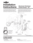
1 Rotate the attachment in each direction to verify it stops
Rotational Control stops
Clamp at vertical positions
A top, B bottom, and C
bilge position.
in vertical and horizontal (bilge) positions.
• If rotation does not stop at vertical or bilge positions,
proceed to Troubleshooting, Section 4.11-3.
A
• If attachment stops in vertical and horizontal (bilge)
positions, proceed to Step 2.
• If rotation does not stop at exact vertical or bilge
positions, limit switches may be adjusted as
described in Step 4.
2 Wait 3 seconds to rotate attachment again, verifying it
To continue rotation after
stopping, wait 3 seconds,
OR press override button.
For continuous rotation,
press and hold button.
C
again stops in the vertical or horizontal (bilge) positions.
3 Press and hold override pushbutton and verify that the
attachment will rotate continuously without stopping.
B
• If continuous rotation does not occur when holding
pushbutton, proceed to Troubleshooting, Section
4.11-3.
AC0231.eps
4 Inspect limit switch end rollers for full engagement on
deceleration ramps and stop capscrews. If required,
adjust limit switch position and/or stop capscrew to
precisely locate stop position within ± 0.5 in. (13 mm).
Limit Switches
(Normally Open)
(Early Model)
4.11-3Stop
Troubleshooting
NOTE: Reference schematic on facing page.
1 Check ERC main power fuse/relay, control lever
pushbutton.
NOTE: Pushbutton is normally closed (NC), providing
power to ERC. Verify the 12V-96V is reaching ERC
control box when truck key is turned on.
2 Inspect all electrical cables.
Look for and correct loose
connections, pinched wiring, or wrongly-connected
cables.
Stop Capscrew
Deceleration Ramp
AC0242.eps
Limit Switches
(Normally Open)
NOTE: Cable connectors and control box are labeled
to show proper connections.
3 Check continuity of solenoid/cable assemblies and limit
switch/cable assemblies and replace if needed.
4 With truck key on, manually operate limit switches and
(Late Model)
listen for 'clicks' at solenoids, indicating solenoid coil
operation. Or, rotate Clamp into ramps and check for
voltage at control box solenoid output connectors.
5 Look for 3-second time delay between rotation
decelerating and ability to restart rotation. If there is
no delay, or Clamp will not rotate continuously with
pushbutton depressed, replace ERC control box.
NOTE: Control box contains adjustable time delay,
contact Cascade for adjustment procedure.
AC1214.eps
Deceleration/Stop Ramp
674512-R7
53