1
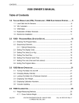
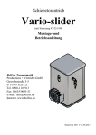
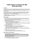
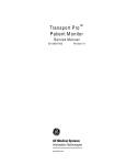
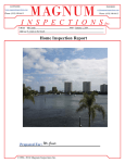
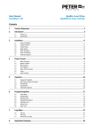
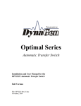
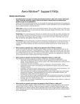
CONTENTS
1
V200 SERVICE MANUAL
Table of Contents
1.0 VULCAN V200 ON-BOARD SCALE SYSTEM ......................................................3
1.1 Load Cells And Pressure Sensors .......................................................................4
1.2 Vulcoders.............................................................................................................5
1.3 Meters..................................................................................................................5
1.4 Electronic Installation...........................................................................................7
2.0 METER OPERATION .......................................................................................9
2.1 Turning The Meter On .........................................................................................9
2.2 Locking The Meter On A Particular Channel .......................................................9
2.3 Displaying Tare Weight........................................................................................9
2.4 Displaying Calibration Numbers...........................................................................9
3.0 WEIGHT MEASURING METHODS ....................................................................11
3.1 Gross Vehicle Weight ........................................................................................11
3.2 Net Payload Weight ...........................................................................................11
4.0 CALIBRATION AND SYSTEM SET-UP .............................................................13
4.1 Procedure For Entering Starting Calibration Numbers.......................................13
4.2 Procedure For Entering Tare Weights ...............................................................14
4.3 Calibration Procedure For Gross Vehicle Weight Methods................................16
4.4 Verifying Tare Weights ......................................................................................17
4.5 Keeping Records ...............................................................................................19
5.0 MAINTENANCE .............................................................................................21
5.1 Driver’s Daily Vehicle Inspection........................................................................21
5.2 Preventive Maintenance And Vulcan Torque Specifications..............................23
5.3 Meter Button Replacement And Cleaning..........................................................27
5.3.1 Disassemble Procedure..........................................................................27
5.3.2 Re-Assemble Procedure.........................................................................28
January 2004
VULCAN ON-BOARD SCALES 1-800-237-0022
© STRESS-TEK, INC.
Doc. 44-10015-001 Rev A.
2
CONTENTS
6.0 TROUBLESHOOTING ..................................................................................... 29
6.1 Vulcan Check-Out Box ......................................................................................30
6.2 Load Cell Evaluation Tests ................................................................................31
6.2.1 Leakage Test Procedure ........................................................................31
6.2.2 Tare Test Procedure...............................................................................33
6.2.3 Resistance Test Procedure ....................................................................35
6.2.4 Vulcoder Check-Out Procedure ..............................................................36
6.3 V200 Meter Error Codes....................................................................................36
6.3.1 Err 1........................................................................................................37
6.3.2 Err 2........................................................................................................38
6.3.3 Err 3........................................................................................................38
6.3.4 Err 4........................................................................................................39
6.3.5 Err 5........................................................................................................39
6.3.6 Err 6........................................................................................................39
6.4 System Malfunctions .........................................................................................40
6.4.1 No Indicator Display Or Functioning Lights.............................................40
6.4.2 Unable To Enter Tare Or Calibration Numbers.......................................41
6.4.3 Meter Reading Drifts Or Wanders With Time .........................................42
6.4.4 Meter Reading Does Not Change When Truck Is Being Loaded............44
6.5 Troubleshooting Worksheet...............................................................................45
6.6 Troubleshooting Assistance And Replacement Parts ........................................47
7.0 APPENDIX ................................................................................................... 48
7.1 Starting Calibration Numbers.............................................................................49
7.2 Identify V200 Vulcoders.....................................................................................50
7.3 Fine Tuning Your Scale System ........................................................................51
7.4 System Specifications .......................................................................................53
January 2004
VULCAN ON-BOARD SCALES 1-800-237-0022
© STRESS-TEK, INC.
Doc. 44-10015-001 Rev A.
CHAPTER 1
CHAPTER
3
1.0
VULCAN V200 ON-BOARD SCALE SYSTEM
Vulcan On-Board Scales are installed on all types of vehicles including, hook lifts, logging trucks,
flatbed trailers, chip trailers, and many other commercial vehicles requiring scales. Total truck
payload weights and gross vehicle weights can be measured using the Vulcan On-Board Scale System.
Typically a scale system has either four or six load cells, two Vulcoders, and one meter per truck. The
number of load cells required depends on the truck’s length and the load capacity.
Vulcan Scale System
Load Cells
Vulcoders
Meter
Figure 1-A Typical Long Logger System
January 2004
VULCAN ON-BOARD SCALES 1-800-237-0022
© STRESS-TEK, INC.
Doc. 44-10015-001 Rev A.
4
1.1
CHAPTER 1
LOAD CELLS
Vulcan load cells and pressure sensors are machined from solid blocks of high strength steel. The
Strain gages are bonded inside the load cell or pressure sensor to sense extremely small dimensional
changes in the material. A strain gage is a precision electrical resistance element. When force is
applied to these sensors, the strain gages stretch or compress, causing a change in output signal
voltage.
Example: Vulcan Super - Beam Load Cell
Figure 1-B: Vulcan Super - Beam Load Cell
(Covered by one or more of the following patents:
US Patent RE. 35,301, 4,459,863
Canadian Patent 1,245,677)
January 2004
VULCAN ON-BOARD SCALES 1-800-237-0022
© STRESS-TEK, INC.
Doc. 44-10015-001 Rev A.
CHAPTER 1
1.2
5
VULCODERS
The primary functions of the Vulcoder are to supply the load cells with power and to relay the load
cells’ output to the meter. The Vulcoder receives a 12 Vdc input from the meter and supplies the load
cells with 7.5 Vdc +/- .5 Vdc. When weight is applied, the voltage output of the load cells change.
The Vulcoder then reads the change in voltage from the load cells and converts it from an analog to a
digital signal. This signal is then relayed to the meter and displayed as weight.
Figure 1-C: Vulcan Electronics Diagram
1.3
METER
The V200 meter’s primary functions are to supply the Vulcoder with 12 Vdc and to read the digital
signal transmitted from the Vulcoder. The meter reads the digital signal, makes calculations, and
displays a weight in pounds or kilograms. The V200 meter is shown on the following page together
with a description of the meter button functions.
January 2004
VULCAN ON-BOARD SCALES 1-800-237-0022
© STRESS-TEK, INC.
Doc. 44-10015-001 Rev A.
6
CHAPTER 1
Figure 1-D: V200 Meter
POWER BUTTON:
Turns the meter on and off.
UP/ DOWN ARROW BUTTONS:
Used to increase or decrease the Cal Number and Tare Number.
CYCLE BUTTON:
Used to view the weight on different channels.
CAL BUTTON:
Used to view and adjust the Cal Number for a particular channel.
TARE BUTTON:
Used to view and adjust the Tare Weight for a particular channel.
January 2004
VULCAN ON-BOARD SCALES 1-800-237-0022
© STRESS-TEK, INC.
Doc. 44-10015-001 Rev A.
CHAPTER 1
7
1.4
ELECTRONICS INSTALLATION
1.
Tape Vulcoder connectors prior to routing cabling to avoid contamination. Mount Vulcoders
on inside of truck frame rail or next to a structural member. Mounting surface must be in an
area protected from road or hauling debris.
2.
Route black cable to load cells. (Do not trim black cable to length).
3.
Important: Check connectors to make sure they are clean and dry. Turn meter off while
making any wire connections. Do not get moisture, contact cleaner, or any other substance
inside of connectors.
4.
Check load cell connector coming from the Vulcoder for O-ring. Attach black cable
connectors to bulkhead connectors on load cells. Make sure they are finger tight plus an
additional 1/8 of a turn with channel lock pliers. The additional tightening is necessary to
compress O-ring preventing scale errors, which can occur from moisture entering into the load
cell connector. Caution: Do not over tighten the connectors as this can damage them.
5.
Route orange Vulcoder cable to cab.
Note: On truck-to-trailer connection, these wires may be routed using the existing truck /
trailer wire harness if two unused, ungrounded wires are available. Additionally, you may
follow the existing wire harness and use a separate connector of your choice between the truck
and trailer.
6.
Find suitable location for the meter and install mounting bracket. Secure cable so it does not
obstruct other in cab equipment, strain relief Vulcoder orange cable, and cut to length. Unplug
terminal block from back of meter, strip wires, and make all wire connections to terminal block
(refer to Figures 1-E and 1-F). Do not plug terminal block into meter at this time.
7.
Disassemble positive fuse holder, (red wire). Connect fused power leads directly to battery for
best operation. If not connecting directly to the battery be sure to use a location that has the
proper 12 Vdc available at all times, refer to Section 7.4 “System Specifications.”
January 2004
VULCAN ON-BOARD SCALES 1-800-237-0022
© STRESS-TEK, INC.
Doc. 44-10015-001 Rev A.
8
CHAPTER 1
Note: Some trucks are configured with variable voltage supplies, never apply more than 16
Vdc to the Vulcan system. Apply grease to the positive connector at the battery post to inhibit
corrosion.
8.
Review steps 1 to 7 before connecting terminal block to back of meter.
Figure 1-E: Stripping Wires for Meter
Figure 1-F: Wire Connections to Meter
January 2004
VULCAN ON-BOARD SCALES 1-800-237-0022
© STRESS-TEK, INC.
Doc. 44-10015-001 Rev A.
CHAPTER 2
CHAPTER
9
2.0
METER OPERATION
2.1
TURNING THE METER ON
This can be done by pressing the Power button on the meter.
2.2
LOCKING THE METER ON A PARTICULAR CHANNEL
To lock the meter on a particular channel, press the Cycle button until the channel light is
displayed. Press the Cycle button again, the meter is now locked on a specific channel.
Channel Designations for Figures 2-A and 2-B.
Channel A :
Represents the truck or front load cells, regardless of whether it is a four or a six
cell configuration.
2.3
Channel B:
Represents the trailer or rear load cells.
Channel A+B:
Represents the total weight from the front and rear load cells.
DISPLAYING TARE WEIGHT
Lock the meter on Channel A or B. The Tare Weight is the displayed reading when the vehicle
is empty. For setting the Tare Weight, refer to Chapter 4.0 “Calibration and System Set-up”.
2.4
DISPLAYING CALIBRATION NUMBERS
Lock the meter on Channel A or B. Press and hold the Cal button to display the Calibration
Number. For setting the Calibration Numbers, refer to Chapter 4.0 “Calibration and System
Set-up”.
January 2004
VULCAN ON-BOARD SCALES 1-800-237-0022
© STRESS-TEK, INC.
Doc. 44-10015-001 Rev A.
10
CHAPTER 2
Figures 2-A and 2-B: Vulcan 4 and 6 cell configurations
January 2004
VULCAN ON-BOARD SCALES 1-800-237-0022
© STRESS-TEK, INC.
Doc. 44-10015-001 Rev A.
CHAPTER 3
CHAPTER
11
3.0
WEIGHT MEASURING METHODS
The Vulcan Scale System can be used to measure weight by two different methods. These methods
are Gross Vehicle Weight, and Net Payload Weight.
3.1
GROSS VEHICLE WEIGHT
Gross Vehicle Weight :
Entire truck weight including fuel, equipment, personnel,
and payload.
In order to use the Gross Vehicle Weight method, the Tare Weight for Channel A and Channel B must
be entered. The Tare Weight is the weight of the empty truck with fuel, equipment, personnel and no
payload. For example if the Tare Weight is 30,000 lb, the meter will display this weight before any
payload has been loaded. As the payload increases, the weight displayed on the meter will also
increase. The weight displayed on Channel A at all times is the Gross Truck Weight. The weight
displayed on Channel B at all times is the Gross Trailer Weight and the weight displayed on Channel
A + B is the Total Gross Vehicle Weight (truck and trailer).
3.2
NET PAYLOAD WEIGHT
Net Payload Weight:
Weight of the truck’s payload only.
By using the Net Payload Weight method, payload pickups are measured cumulatively. Net Payload
Weight can be measured when the truck’s Tare Weight is set to zero. If the Tare Weight for Channel
A and Channel B are set to zero, the weight displayed at all times during the route is the Net Payload
Weight.
January 2004
VULCAN ON-BOARD SCALES 1-800-237-0022
© STRESS-TEK, INC.
Doc. 44-10015-001 Rev A.
12
January 2004
CHAPTER 3
VULCAN ON-BOARD SCALES 1-800-237-0022
© STRESS-TEK, INC.
Doc. 44-10015-001 Rev A.
CHAPTER 4
CHAPTER
13
4.0
CALIBRATION AND SYSTEM SET-UP
Calibration is fine tuning a system to maximum accuracy in reference to a specific certified platform
scale. It is important to calibrate for high accuracy in order to achieve the maximum possible payload.
It is also important that conditions remain as constant as possible throughout the calibration process.
Inaccuracies may result from differences in fuel load, ice build-up, etc. It may take 2 or 3 attempts at
calibration to achieve the optimum setting.
Calibration should be done anytime a system is installed, if there are continuous questionable
readings, or if meter readings repeatably do not closely match the certified platform scale weights.
The Vulcan Scale System can be calibrated for Gross Vehicle Weight and Net Payload Weight. The
Net Payload Weight displays only the weight of the payload and the Gross Vehicle Weight displays
the weight of both the truck and its payload.
4.1
PROCEDURE FOR ENTERING STARTING
CALIBRATION NUMBERS
1.
Stop the empty truck on level ground.
2.
Turn on the meter. Wait for system initialization.
3.
Look up Cal Numbers for Channel A and B in Section 7.1
“Starting Calibration Numbers” and write them in the space provided below.
Starting Channel A Cal Number: ________
4.
Starting Channel B Cal Number : _________
Lock meter on Channel A using the Cycle button.
January 2004
VULCAN ON-BOARD SCALES 1-800-237-0022
© STRESS-TEK, INC.
Doc. 44-10015-001 Rev A.
14
5.
CHAPTER 4
Press and hold Cal button to display Cal Number setting. If setting does not match starting
Channel A Cal Number in Step 3, correct the Cal Number with the Up or Down Arrow
buttons. Note: Holding down the Up or Down Arrow buttons will accelerate the number
change.
6.
Lock the meter on Channel B using the Cycle button.
7.
Press and hold Cal button to display Cal Number setting. If setting does not match starting
Channel B Cal Number in Step 3, correct the Cal Number with the Up or Down Arrow
buttons. Note: Holding down the Up or Down Arrow buttons will accelerate the number
change.
8.
IMPORTANT: Leave the meter on for a minimum of 3 minutes after changing the Cal
Numbers so the new values will be recorded into permanent memory. Starting the truck or
turning the ignition switch during this time will cause the meter to reset and go back to a
previous setting.
4.2
PROCEDURE FOR ENTERING TARE WEIGHTS
GROSS VEHICLE WEIGHT METHOD
1.
Weigh the entire empty truck (both front and rear axles) using a certified platform scale. This
is the truck’s Tare Weight. Enter this number in the space provided.
Tare Weight of Entire Empty Truck
2.
_____________
Weigh the entire empty trailer (all axles). This is the trailer’s Tare Weight. Enter this
number in the space provided.
Tare Weight of Entire Empty Trailer
3.
_____________
Stop the empty truck and trailer on level ground.
January 2004
VULCAN ON-BOARD SCALES 1-800-237-0022
© STRESS-TEK, INC.
Doc. 44-10015-001 Rev A.
CHAPTER 4
4.
15
With the truck empty, lock the meter on Channel A using the Cycle button. The displayed
weight is the Tare Weight. Note: The truck and trailer must not be in a twist or turn.
5.
Press and hold the Tare button to display Tare Reference Number. Use the Up or Down
Arrow buttons to change the value displayed, so when the Tare button is released, it matches
the Empty Truck weight. Note: When Tare button is held down the number displayed is not
the Tare Weight.
6.
Lock the meter on Channel B using the Cycle button. The displayed weight is the Tare
Weight.
7.
Press and hold the Tare button to display Tare Reference Number. Use the Up or Down
Arrow buttons to change the value displayed, so when the Tare button is released it matches
the Empty Trailer Weight. Note: When Tare button is held down the number displayed is not
the Tare Weight.
8.
IMPORTANT: Leave the meter on for a minimum of 3 minutes after changing the Tare
Weight so the new values will be recorded into permanent memory. Starting the truck, turning
the ignition switch during this time will cause the meter to reset and return to a previous
setting.
January 2004
VULCAN ON-BOARD SCALES 1-800-237-0022
© STRESS-TEK, INC.
Doc. 44-10015-001 Rev A.
16
4.3
CHAPTER 4
CALIBRATION PROCEDURE FOR GROSS
VEHICLE WEIGHT METHODS
1.
Fully load the truck close to the legal limit.
2.
Weigh the loaded truck and then the loaded trailer using same certified scale, write them here:
a)
Channel A Loaded Weight:
(Loaded truck)
b)
Channel B Loaded Weight:
(Loaded trailer)
3.
Park on level ground.
4.
Lock meter on Channel A using the Cycle button to display weight. If displayed weight does
not match** Channel A Loaded Weight in Step 2, correct as follows:
a)
Press and hold Cal button down to display Cal Number.
b)
Use the Up or Down button to increase or decrease the Cal Number until the value
displayed when the Cal button is released matches Channel A loaded truck weight
above.
5.
Lock meter on Channel B using the Cycle button to display weight. If displayed weight does
not match** Channel B Loaded Weight in Step 2, correct as follows:
a)
Press and hold Cal button down to display Cal Number.
b)
Use the Up or Down button to increase or decrease the Cal Number until the value
displayed when the Cal button is released matches Channel B loaded truck weight
above.
January 2004
VULCAN ON-BOARD SCALES 1-800-237-0022
© STRESS-TEK, INC.
Doc. 44-10015-001 Rev A.
CHAPTER 4
17
Figure 4-A: Truck Gross Weight (Channel A) in Relation to a Certified Platform Scale
** With in 1% of gross vehicle weight. It is common for operators to calibrate better than 1%.
If additional assistance is needed to fine tune your scale system, please follow the instructions shown
in Section 7.3 “Fine Tuning Your Scale System”.
4.4
VERIFYING TARE WEIGHTS
1.
Unload truck.
2.
Park on level ground.
3.
Lock meter on Channel A using the Cycle button to display Tare Weight.
If displayed Tare Weight matches (+/- 400 lb) Channel A Tare Weight originally set into
meter, you have successfully calibrated this channel. Go to Step 4.
If displayed Tare Weight does not match (+/- 400 lb) Channel A Tare Weight originally set
into meter, continue to fine tune the calibration by repeating the process beginning at Section
4.3.
January 2004
VULCAN ON-BOARD SCALES 1-800-237-0022
© STRESS-TEK, INC.
Doc. 44-10015-001 Rev A.
18
4.
CHAPTER 4
Lock meter on Channel B using the Cycle button to display Tare Weight.
If displayed Tare Weight matches (+/- 400 lb) Channel B Tare Weight originally set into
meter, you have successfully calibrated this channel.
If displayed Tare Weight does not match (+/- 100 lb) Channel B Tare Weight originally set
into meter, continue to fine tune the calibration by repeating the process beginning at section
4.3.
5.
IMPORTANT: Leave the meter on for a minimum of 3 minutes after changing the Tare
or Cal Numbers so the new values will be recorded into permanent memory. Starting the
truck, turning the ignition switch during this time will cause the meter to reset and return to a
previous settings.
January 2004
VULCAN ON-BOARD SCALES 1-800-237-0022
© STRESS-TEK, INC.
Doc. 44-10015-001 Rev A.
CHAPTER 4
19
4.5
KEEPING RECORDS
1.
Lock meter on Channel A using Cycle button.
2.
Read displayed Tare Weight shown on meter display, write below.
3.
Press and hold the Cal button to display Cal Number, write below.
4.
Lock meter on Channel B using the Cycle button.
5.
Read displayed Tare Weight shown on meter display, write below.
6.
Press and hold Cal button to display Cal Number, write below.
CALIBRATION NUMBERS - QUICK REFERENCE
Channel A Tare Number:
Final Channel A Cal Number:
Channel B Tare Number:
Final Channel B Cal Number:
Most Important:
•
Adjust the Tare Number only when empty.
•
Adjust the Cal Number only when loaded.
January 2004
VULCAN ON-BOARD SCALES 1-800-237-0022
© STRESS-TEK, INC.
Doc. 44-10015-001 Rev A.
20
January 2004
CHAPTER 4
VULCAN ON-BOARD SCALES 1-800-237-0022
© STRESS-TEK, INC.
Doc. 44-10015-001 Rev A.
CHAPTER 5
CHAPTER
21
5.0
MAINTENANCE
In order to keep any system functioning properly, it is important that the system be properly
maintained. This includes daily vehicle inspections and preventive maintenance.
5.1
DRIVER’S DAILY VEHICLE INSPECTION
1.
Check load cells, mounting brackets, and fasteners. Make sure they are secure.
2.
If torque stripes have been applied, make sure they are properly aligned. To apply a torque
stripe: Use a durable, brightly colored paint. Paint a stripe crossing the head of the fastener,
continuing down the fastened structure, as shown.
Figure 5-A: Painting a Torque Stripe
3.
Check and remove any build up of mud, ice, or other debris that may obstruct the load cell load
path. Refer to the drawing below and Section A in Figures 5-C through 5-F.
January 2004
VULCAN ON-BOARD SCALES 1-800-237-0022
© STRESS-TEK, INC.
Doc. 44-10015-001 Rev A.
22
CHAPTER 5
Figure 5-B: Load Path Diagram
4.
Check the meter mounting and wiring, make sure they are secure.
5.
Check the green plug attached to the back of the meter. Make sure it is secure.
6.
Check the system. Make sure the meter powers up after it has been turned on, digits are
legible, and the system functions normally.
7.
Check all wiring for condition (no cracks or splits), security, chaffing, and protection from
possible damage.
January 2004
VULCAN ON-BOARD SCALES 1-800-237-0022
© STRESS-TEK, INC.
Doc. 44-10015-001 Rev A.
CHAPTER 5
5.2
23
PREVENTIVE MAINTENANCE AND VULCAN
TORQUE SPECIFICATIONS
The following simple, but important, preventive maintenance steps must be performed periodically
after 500 miles, monthly afterwards, or more frequently, if needed.
1.
Look for mud, ice buildup, or other debris between the load cell and bracket. Refer to
location A shown on Figures 5-C through 5-F.
2.
Check load cell connectors (refer to location B shown on Figures 5-C through 5-F ), make
sure they are finger tight plus an additional 1/8 of a turn with channel lock pliers. The
additional tightening is necessary to prevent scale errors, which can occur from moisture
entering into the load cell connector. Do not grease or lubricate inside the Vulcan load cell
connector or Vulcoder connector. These components are highly sensitive to foreign
substances and inaccurate readings will occur if these components are contaminated. Your
manufacturer’s warranty does not cover the failure of Vulcan components due to
contamination (use of grease or other conductive substance) in either the Vulcan load
cell connectors or Vulcoder connectors. If a connector is opened for any reason, you
must clean the load cell connector and cable connector with cotton swabs and isopropyl
alcohol, dry with a hair dryer (DO NOT OVERHEAT), and replace the O-ring before
reconnecting.
3.
Check the torque on load cell cap screws monthly. New trucks must be checked once a week
for 2 weeks. Vulcan On-Board Scales recommended torque values are shown on Figures 5-C
through 5-F and general torque values shown below. As a method of monitoring changes in
fastener torque, Vulcan On-Board Scales recommends applying torque stripes to all fasteners
(see Section 5.1, step 2).
Torque Specifications:
lb-ft
January 2004
5/8"
3/4"
210-240
400-500
7/8"
400-590
VULCAN ON-BOARD SCALES 1-800-237-0022
© STRESS-TEK, INC.
1"
1-1/8"
650-890
1000-1400
Doc. 44-10015-001 Rev A.
24
4.
CHAPTER 5
Vulcan load cells are plated for increased rust protection. Certain minimum maintenance
will be necessary to claim warranty of load cells. Annually,
apply a high quality paint to the load cells, bearing pads, and mounting brackets. For
environments where high concentrations of salts are used on road surfaces, undercoating is
recommended (3M, Universal Rubberized Undercoating, 3M P/N: 8883). Spray undercoating
when load cells are connected to electronics and fully assembled with bearing pads and
brackets. See “Vulcan Load Cell Maintenance” document 44-20006-001 for further details.
5.
Fill unused holes in load cells with grease to protect against rust. Never grease the inside of
the connector.
6.
Check welds on load cell brackets. IMPORTANT: If a weld repair is required, either
remove the load cell or do not exceed 140 degrees Fahrenheit (60 degrees Celsius) on the
load cell. Arcing on the body of the load cell may seriously damage the load cell’s
structural integrity and must NOT be installed if this occurs. This also voids the
manufacturer’s warranty.
7.
Check all wiring for condition, routing, and protection.
8.
Check meter for secure mounting and strain relief of wires.
9.
Check system for functionality.
10.
Review and address any driver concerns.
January 2004
VULCAN ON-BOARD SCALES 1-800-237-0022
© STRESS-TEK, INC.
Doc. 44-10015-001 Rev A.
CHAPTER 5
25
Typical Western Logger Mounting
Figure 5-C
Typical Hutch or Transpro Center Hanger Mounting
Figure 5-D
January 2004
VULCAN ON-BOARD SCALES 1-800-237-0022
© STRESS-TEK, INC.
Doc. 44-10015-001 Rev A.
26
CHAPTER 5
Typical Single Point Mounting
Figure 5-E
Typical Holland 5th Wheel Mounting
Figure 5-F
January 2004
VULCAN ON-BOARD SCALES 1-800-237-0022
© STRESS-TEK, INC.
Doc. 44-10015-001 Rev A.
CHAPTER 5
5.3
27
METER BUTTON REPLACEMENT AND CLEANING
Figure 5-G
5.3.1 DISASSEMBLE PROCEDURE
1.
First remove meter from truck.
2.
Remove defective or dirty button using a small screwdriver. Place the blade under the lip of
the button and gently pry up. Note: It is not necessary to disassemble meter to remove
buttons.
3.
Lift out metal dome switch from switch base as shown in Figure 5-G. Caution: Care must be
taken not to drop the switch dome inside the meter. If the switch dome does get inside, it will
have to be removed before the meter is plugged into the power source.
4.
Clean out any dirt that may be in the switch base. Clean the center contact. This can be done
by lightly scraping or by using a pencil eraser.
January 2004
VULCAN ON-BOARD SCALES 1-800-237-0022
© STRESS-TEK, INC.
Doc. 44-10015-001 Rev A.
28
CHAPTER 5
5.3.2 RE-ASSEMBLE PROCEDURE
1.
Place the silver and gold switch dome in the switch base with the gold side towards the meter
and the silver raised dome facing out.
2.
Snap the new plastic button into position by using a small screwdriver (place the blade against
the lip of the button and gently press in). The taper surface face needs to be installed as shown
in Figure 5-G.
3.
Re-install the meter, turn it on, an check the function of the buttons.
NOTE: If button starts sticking, disassemble the switch as described. Clean both the center
contact in the base and switch dome. Re-assemble.
January 2004
VULCAN ON-BOARD SCALES 1-800-237-0022
© STRESS-TEK, INC.
Doc. 44-10015-001 Rev A.
CHAPTER 6
CHAPTER
29
6.0
TROUBLESHOOTING
In general, troubleshooting is a systematic process of testing and eliminating potential problem
sources until the one that is causing the problem is found. The problem can then be fixed by repairing
or replacing the faulty part.
With a little knowledge, and by following a step by step procedure, most of the problems that you may
encounter will be easy to diagnose and cure. In this section, you will find guidelines on how to
troubleshoot the system, some characteristics of a properly functioning system, and where to look
when certain problems occur.
Occasionally, someone has a problem that is not described here. Do not panic. By approaching the
problem systematically, you will be able to eliminate potential sources of trouble until you find the
one that is causing the problem.
The following section covers an explanation of Load Cell Evaluation Test Procedures and Vulcan
Error Codes. If a problem occurs and no Error Codes appear, use the V200 Meter to isolate the
problem to either Channel A or B.
January 2004
VULCAN ON-BOARD SCALES 1-800-237-0022
© STRESS-TEK, INC.
Doc. 44-10015-001 Rev A.
30
6.1
CHAPTER 6
VULCAN CHECK-OUT BOX
The Vulcan Check-Out Box works as an extension to bring connector pins to the side of truck where
readings can be conveniently made and it can also simulate an applied load to the Vulcoder. The
Check-Out Box is required equipment for the Vulcoder Check-Out Procedure (Section 6.2.4) and is an
optional equipment item for the Leakage and Resistance Tests (Section 6.2.1 and 6.2.3).
Before using the Check-Out Box, make sure the meter fuses are good. Use a multi-meter to ensure
there is a minimum of 12 Vdc at the back of the meter . (Make sure the green plug is plugged in and
the meter is turned on.) If there are any error messages displayed refer to Section 6.3 “V200 Meter
Error Codes”.
Figure 6-A: Vulcan Check-Out Box
To order a Check-Out Box (P/N: 56-10425-001), contact your Vulcan dealer.
January 2004
VULCAN ON-BOARD SCALES 1-800-237-0022
© STRESS-TEK, INC.
Doc. 44-10015-001 Rev A.
CHAPTER 6
6.2
31
LOAD CELL EVALUATION TESTS
The tests listed below will help identify and locate any problem you may encounter with your Vulcan
Scale System.
Leakage Test
Tare Test
Resistance Test
Vulcoder Check-Out Test
6.2.1 LEAKAGE TEST PROCEDURE
Required Equipment:
Multi-meter
Isopropyl Alcohol
Cotton Swabs
Hair Dryer
Optional Equipment:
Vulcan Check-Out Box
The Leakage Test Procedure detects the presence of moisture that could cause erratic meter readings.
The way to measure leakage is to use a digital multi-meter that has a conductivity scale. Electrical
isolation is measured between any pin and an unpainted clean surface on the load cell or the connector
body. Electrical isolation must not exceed 2.0 nS (nano-siemans) or be less than 500 Meg Ohms.
Refer to Figure 6-B for the Leakage Test equipment set-up. If a Vulcan Check-Out Box is used, it is
important that the Vulcoder leads from the load cells of the channel being tested are disconnected.
For proper operation, the power and signal leads from the load cell must have a very high resistance to
the load cell body. An electrical path between the wires and the body would indicate moisture in the
cell or shorting to the body. This would result in erratic, fluctuating, or even out of range weight
displays.
If the load cell fails (electrical isolation is greater than 2.0 nS or is less that 500 Meg Ohms), check the
inside of the load cell connector with a dry cotton swab to make sure it is clean and dry. If not, clean
with isopropyl alcohol, dry with a hair dryer, and check the electrical isolation again.
January 2004
VULCAN ON-BOARD SCALES 1-800-237-0022
© STRESS-TEK, INC.
Doc. 44-10015-001 Rev A.
32
CHAPTER 6
Caution: Do not touch the probes with your hands when making measurements. This could cause an
error in the meter reading. A person’s body can have 10 times the allowable conductivity of a load
cell.
OR
Leakage Test Specifications:
Measured between any pin and an unpainted clean surface of the load cell or connector body.
Electrical Isolation should not be greater than 2.0 nS or less than 500 Meg Ohms.
Figure 6-B: Leakage Test
If the load cell cannot be brought to Vulcan specifications, contact your Vulcan dealer.
January 2004
VULCAN ON-BOARD SCALES 1-800-237-0022
© STRESS-TEK, INC.
Doc. 44-10015-001 Rev A.
CHAPTER 6
33
6.2.2 TARE TEST PROCEDURE
Required Equipment:
Vulcan V200 Meter
Isopropyl Alcohol
Cotton Swabs
O-rings
Hair Dryer
Channel Lock Pliers
Checks each load cell for a high Preload Number caused by mechanical damage or moisture.
1.
Park the empty truck on level ground.
2.
Use the Cycle button to lock the meter on Channel A or B where the load cells will be tested.
3.
Record the current Tare Weight.
Current Tare Weight
4.
___________
Press and hold the Tare button. Use the Up or Down Arrow buttons to change the display to
read zero.
5.
Press and hold the Cal button. Write down the current Cal Number.
Current Cal Number
__________
Then change the Cal Number using the Up or Down Arrow buttons to display 2050.
January 2004
VULCAN ON-BOARD SCALES 1-800-237-0022
© STRESS-TEK, INC.
Doc. 44-10015-001 Rev A.
34
6.
CHAPTER 6
Clean and re-connect each load cell to the Vulcoder one at a time. The meter will display the
load cell Preload Number. The Preload Number should fall between +12,000 to -12,000
counts.
If the Preload Number exceeds +12,000 to -12,000 counts, proceed with steps 6-a to 6-f.
a) Clean the load cell connector and cable connector with cotton swabs and isopropyl alcohol.
b) Dry thoroughly with a hair dryer. DO NOT OVERHEAT.
c) Check the electrical isolation by performing the Leakage Test. (Refer to Section 6.2.1).
d) If a Vulcan Check-Out Box is available, perform the Vulcoder Check-Out Test.
(Refer to Section 6.2.4)
e) Check the Preload Number again to see if it is within the +12,000 lb to - 12,000 lb range.
If the load cell is still out of range, it may be faulty. Perform the Resistance Test.
(Refer to Section 6.2.3)
f) Replace the O-rings before re-connecting.
7.
Measure the Preload Number of the remaining load cells one at a time.
8.
Reset the original Cal Number and Tare Weight.
If the load cell cannot be brought to Vulcan specifications, contact your Vulcan dealer.
January 2004
VULCAN ON-BOARD SCALES 1-800-237-0022
© STRESS-TEK, INC.
Doc. 44-10015-001 Rev A.
CHAPTER 6
35
6.2.3 RESISTANCE TEST PROCEDURE
Required Equipment:
Multi-meter
Optional Equipment:
Vulcan Check-Out Box
Please refer to drawing below in setting up the Resistance Test. The resistance in the pins should
correspond to the Vulcan specifications listed below. This test can be conducted with a multi-meter or
a Vulcan Check-Out Box. Refer to acceptable resistance ranges as shown below.
OR
Figure 6-C Resistance Test
Pins
Terminal
Acceptable
Color Code
Resistance Range
A to D
Red to Black
349 to 400 Ohms
B to C
Green to White
349 to 352 Ohms
Pin B (Green) to Pin A (Red) should be the same number as Pin B (Green) to Pin D (Black) within 1 Ohm.
Pin C (White) to Pin A (Red) should be the same number as Pin C (White) to Pin D (Black) within 1 Ohm.
If the load cell cannot be brought to Vulcan specifications, contact your Vulcan dealer.
January 2004
VULCAN ON-BOARD SCALES 1-800-237-0022
© STRESS-TEK, INC.
Doc. 44-10015-001 Rev A.
36
CHAPTER 6
6.2.4 VULCODER CHECK-OUT PROCEDURE
Required Equipment:
Vulcan V200 Meter
Vulcan Check-Out Box
Using the Cycle button, lock the meter on the Channel that the Vulcoder will be tested on either
Channel A or B. Refer to section 7.2 to identify V200 Vulcoders. Set the Calibration Number to 2050
on the channel being tested (for 2 mV/V Vulcoders, set to 4100, for 3 mV/V Vulcoders, set to 6150).
Set the Tare Reference Number for that channel to zero using the following procedure. Disconnect all
load cells from Vulcoder on the channel being tested. While depressing the Tare button, use the Up
or Down Arrow buttons to make the display read zero. The display must read zero while the Tare
button is depressed. Release the Tare button.
With all load cells disconnected on the channel being tested, plug a Vulcoder lead into the Check-Out
Box (load switch “OFF”). The meter display must read zero (+/- 200 lb). If the Tare Reference
Number is not zeroed, the cabling is damaged. Move the load switch to “ON” indicted by the red dot.
The V200 meter must display 38,200 lb (+/- 200 lb). Check all leads. If any Vulcoder lead does not
perform as stated above, the black Vulcoder cable is damaged and must be inspected and repaired. If
all Vulcoder leads do not perform as stated above, all have been damaged or the Vulcoder needs to be
replaced. Contact your Vulcan dealer for repair or replacement of damaged Vulcoder lead.
6.3
V200 METER ERROR CODES
The V200 Meter is equipped with a self diagnostic program. Should a malfunction occur, the meter
will display an error code. This error code can be used to isolate and identify a problem with the
Vulcan Scale System. If an error code is displayed on the screen while the meter is locked on Channel
A+B, use the Cycle button to isolate the problem to either Channel A or Channel B.
January 2004
VULCAN ON-BOARD SCALES 1-800-237-0022
© STRESS-TEK, INC.
Doc. 44-10015-001 Rev A.
CHAPTER 6
37
Listed below are the error code definitions, possible causes, and procedures to correct the system
malfunction.
6.3.1 Err 1
Indicates that the Vulcoder is processing an over-ranged signal. An over-ranged signal means
that the load cell output is greater than the maximum that the Vulcoder will accept. Err 1 is
displayed briefly when the meter is first turned on and clears after the meter and Vulcoder get
in synch.
Possible Causes:
1.
2.
3.
4.
5.
The load cells are being over-loaded.
There is moisture in a load cell connector.
One of the Vulcoder-to-load cell cables has been damaged.
A load cell is faulty.
A load cell has a large Preload Number.
What to Do:
1.
Check and verify that the Cal Number is reasonable. Refer to Section 7.1 “Starting
Calibration Numbers”.
2.
Perform Tare Test (refer to Section 6.2.2).
3.
Check the load cells. Check by disconnecting one load cell at a time. When the faulty load
cell has been disconnected, the meter will read a number instead of the error code.
4.
Check mounting of the load cell per Section 5.2 “Preventative Maintenance and Vulcan
Torque
January 2004
Specifications”, Figures 5-C to 5-F.
VULCAN ON-BOARD SCALES 1-800-237-0022
© STRESS-TEK, INC.
Doc. 44-10015-001 Rev A.
38
CHAPTER 6
6.3.2 Err 2
Indicates that the reading to be displayed is beyond the limitations of the meter’s display.
Possible Causes:
1.
2.
Cal Number set too high.
Tare Weight set too high.
What to Do:
1. Check and reset Cal Numbers and Tare Weight.
6.3.3 Err 3
Indicates that the meter is not receiving a signal from the Vulcoder (or that a very large over
range signal is being sent to the meter).
Possible Causes:
1.
2.
3.
4.
5.
There is usually an open circuit between the meter and Vulcoder. This is the most common
reason.
Disconnected or broken green or white Vulcoder wires between the back of the meter and the
Vulcoder.
Faulty Vulcoder or meter.
Faulty load cell.
Moisture in the load cell connectors.
What to Do:
1.
Check the wires in the green plug at the back of the meter and ensure that they are firmly in
place. Unplug and plug the connector back in the meter to check for proper connection.
2.
Check the voltage at the back of the meter and Vulcoder. Make sure the voltages match the
required voltages in Section 7.4 “System Specifications”.
3.
Check the orange cable for broken wires.
January 2004
VULCAN ON-BOARD SCALES 1-800-237-0022
© STRESS-TEK, INC.
Doc. 44-10015-001 Rev A.
CHAPTER 6
4.
39
Check the voltage at the load cell connector. Refer to the required load cell voltages in Section
7.4 “System Specifications”. Repair or replace the Vulcoder as necessary.
5.
Disconnect one load cell and then the other to see if this clears the error code. If the error code
is cleared, the load cell may be faulty. Conduct all three load cell tests; Leakage, Tare, and
Resistance (refer to Sections 6.2.1 through 6.2.3).
6.
Replace the O-rings, clean the connector with isopropyl alcohol, and dry with a hair dryer.
Reconnect the load cells.
6.3.4 Err 4
Same as Err 1.
6.3.5 Err 5
This error code is not used.
6.3.6 Err 6
Indicates a malfunctioning Vulcoder circuit. Err 6 may also appear briefly as an over-ranged
signal comes within range.
Possible Causes:
1.
Moisture problem at load cell connector.
2.
Faulty Vulcoder.
What To Do:
1.
Perform checks on page 38, section 6.4.3.
Note: When both load cells are disconnected from the Vulcoder, the meter does not necessarily
display an error message. Often, the meter will display a steady number (e.g. 79100) or it may display
a number that jumps around.
January 2004
VULCAN ON-BOARD SCALES 1-800-237-0022
© STRESS-TEK, INC.
Doc. 44-10015-001 Rev A.
40
6.4
CHAPTER 6
SYSTEM MALFUNCTIONS
6.4.1 No Indicator Display or Functioning Lights
Possible Causes:
1.
Power switch turned off.
2.
Power to the meter has been disconnected.
3.
Bad meter cable connections to the battery.
4.
Battery is low (under 11 Volts).
5.
A fuse is blown in the power or ground cable.
6.
Meter’s internal circuit breaker is blown.
7.
Faulty power switch.
8.
Faulty meter.
9.
Reversed polarity.
What to Do:
1.
Check the power to the meter. When the meter is turned on and off, the power must not
change more than .5 Vdc. If the meter still does not work, proceed to step 2.
2.
Check the fuses for both negative and positive leads. Use 3 amp fast blow fuses only.
3.
Check that the power supply wires are attached correctly at the 12 Vdc power source and to the
green connector at the back of the meter. Check the battery connections for corrosion.
4.
If a spare meter is available, the quickest and easiest next step is to change the meter. If the
new meter works, try the old meter again. If the old meter now works, the problem was likely
the meter’s internal circuit breaker. If both the old meter and the new meter do not work, the
problem is most likely in the power source (battery, meter power cable, or fuses). If the new
meter works, but the old one does not, the old meter is faulty.
January 2004
VULCAN ON-BOARD SCALES 1-800-237-0022
© STRESS-TEK, INC.
Doc. 44-10015-001 Rev A.
CHAPTER 6
41
If you do not have a spare meter, disconnect then reconnect, the green power plug on the back
of the meter. If the meter does not work, then check the power source (battery, meter power
cable, or fuses). If the power sources check out, then the meter is faulty.
6.4.2 Unable To Enter Tare or Calibration Numbers
Possible Causes:
1.
Meter may have dirty button connections.
2.
Faulty buttons.
What to Do:
1.
Check to see if any buttons are defective. (You need to be on Channel A or B, but not A + B).
A.
Press and hold Tare button to display Tare Reference Number. If it does not, then the
Tare button is faulty. (Refer to the maintenance section 5.3, page 27)
B.
Press the Up button. The number displayed will increase. If it does not, then the Up
button is faulty. Check for a dirty or bad connection. (Refer to the maintenance
section 5.3, page 27)
C.
Press the Down button. The number displayed will increase. If it does not, then check
the Down button is faulty. Check for a dirty or bad connection. (Refer to the
maintenance section 5.3, page 27).
D.
Press and hold Cal button to display Cal Number. If it doesn’t then the Cal button is
faulty. (Refer to the maintenance section 5.3, page 27)
January 2004
VULCAN ON-BOARD SCALES 1-800-237-0022
© STRESS-TEK, INC.
Doc. 44-10015-001 Rev A.
42
CHAPTER 6
6.4.3 Meter Reading Drifts or Wanders With Time
Possible Causes:
1.
Voltage to meter or Vulcoder is less than 12.3 Vdc.
2.
Voltage out of the Vulcoder is less than the voltage output required as stated in Section 7.3
“System Specifications.”
3.
Moisture in a load cell connector.
4.
Damaged cable between Vulcoder and load cell.
5.
Bad connection on green connector or broken wire or cable between meter and the Vulcoder.
6.
Faulty load cell.
What to Do:
1.
Using a voltmeter, check the voltage at the back of the meter. Refer to the required meter
voltages in Section 7.4 “System Specifications”.
2.
Check the black 4-wire cabling between the load cells and the Vulcoder. If the cabling is
damaged, contact your Vulcan dealer for Vulcoder repair.
3.
Measure the voltage between pins A and D of the Vulcoder connector. If it measures less than
7.5 Vdc (+/- .5 Vdc), make sure the Vulcoder cable is securely attached to the meter green plug
and the length of the orange cable from the Vulcoder to the meter is not longer than 100 ft.
Also check any truck / trailer connectors in the Vulcoder signal cable.
4.
Before proceeding, clean the load cell connector and cable connector with isopropyl alcohol
and cotton swabs, then dry with a hair dryer. Do not overheat. Reconnect and operate system
for one day to see if the problem is fixed. If the problem is not fixed, continue to step 5.
January 2004
VULCAN ON-BOARD SCALES 1-800-237-0022
© STRESS-TEK, INC.
Doc. 44-10015-001 Rev A.
CHAPTER 6
5.
43
If two load cells are connected per Vulcoder, follow steps, 5a and 5b.
a.
Disconnect the cable to the right load cell. Watch the meter display the number for a
period of 5 minutes. If it wanders more than 200 lb (100 kg), make a note of it. Then,
clean and reconnect the right load cell.
b.
Disconnect the cable to the left load cell. Watch the meter display the number for
period of 5 minutes. If it wanders more than 200 lb (100 kg), make a note of it. Then,
clean and reconnect the left load cell.
If any one of the load cells wanders more than 200 lb (100 kg), perform the Leakage and Resistance
tests (refer to Sections 6.2.1 and 6.2.3). If both of the load cells wander more than 200 lb (100 kg),
then the Vulcoder is faulty and needs to be checked (refer to Section 6.2.4 “Vulcoder Check-Out
Procedure”).
If four load cells are connected per Vulcoder, follow steps, 5c and 5f.
c.
For Vulcoders with 4 load cells, disconnect the cables to all the load cells except the
right front load cell. Watch the meter display a number for a period of 5 minutes. If it
wanders more than 200 lb (100 kg), make a note of it.
d.
Disconnect right front load cell and reconnect right rear load cell. Watch the meter
display for 5 minutes. If it wanders more than 200 lb (100 kg), make a note of it.
e.
Disconnect the right rear load cell and reconnect the left rear load cell. Watch the
meter display for 5 minutes. If it wanders more than 200 lb (100 kg), make a note of
it.
f.
Disconnect the left rear load cell and reconnect the left front load cell. Watch the
meter display for 5 minutes. If it wanders more than 200 lb (100 kg), make a note of
it.
January 2004
VULCAN ON-BOARD SCALES 1-800-237-0022
© STRESS-TEK, INC.
Doc. 44-10015-001 Rev A.
44
CHAPTER 6
If any one of the load cells wanders more than 200 lb (100 kg), perform the Leakage and Resistance
tests (refer to Sections 6.2.1 and 6.2.3). If all of the load cells wander more than 200 lb (100 kg) then
the Vulcoder is faulty and needs to be checked (refer to Section 6.2.4 “Vulcoder Check-Out
Procedure”).
6.4.4 Meter Reading Does Not Change When Truck Is Being Loaded
Possible Causes:
1.
Voltage to meter is below 12.3 Vdc.
2.
Mud or ice build-up under the load cells.
3.
Calibration Number on the meter is set too low.
4.
Faulty load cell.
5.
Broken wire or bad connection between the load cell and Vulcoder.
What to Do:
1.
Using a voltmeter, check the power at the meter’s green plug at the back of the meter. Refer
to Section 7.4 “System Specifications”. If the voltage is below 12 Vdc, the problem could be
in the power source (battery, meter power cable, and / or fuses).
2.
Reset the meter by unplugging the green connection on the back of the meter for a few
seconds.
3.
Refer to Section 7.1 “Starting Calibration Numbers”, to verify that the Cal Number is within
range.
4.
Check the black cables between the load cells and the Vulcoder. If the cabling is damaged the
Vulcoder needs to be repaired or replaced. Contact your Vulcan dealer.
5.
Perform the Leakage, Tare, and Resistance Tests (refer to Sections 6.2.1 through 6.2.3).
January 2004
VULCAN ON-BOARD SCALES 1-800-237-0022
© STRESS-TEK, INC.
Doc. 44-10015-001 Rev A.
CHAPTER 6
6.5
45
TROUBLESHOOTING WORKSHEET
Briefly describe your problem:
Do you have Vulcan electronics? If not, whose?
Do you have all Vulcan load cells?
If not, whose Channel A load cells?
If not, whose Channel B load cells?
HISTORY
Were the scales put on a new vehicle or were they retrofitted?
How long have you had this system?
Has the system ever worked?
How long has the current driver been using the vehicle?
Has there been any mechanical work or maintenance done to the vehicle,
changed bridge beam, bunk, etc.?
Has there been any electrical work or maintenance done to the vehicle,
battery work, generator / alternator problems, added accessories, jump start?
Has there been any recent maintenance of the scale system, parts
exchanged, etc.?
Has anything else happened to the rig such as an accident?
SYMPTOMS
Does the problem occur on Channel A or B, or both?
Does the meter drift up and / or down, fast or slow, or both?
Is the problem intermittent, constant, or both?
Does problem occur on flat road or off-road or both?
January 2004
VULCAN ON-BOARD SCALES 1-800-237-0022
© STRESS-TEK, INC.
Doc. 44-10015-001 Rev A.
46
CHAPTER 6
Does it occur in wet or dry weather or both?
Does it occur at morning, at night, or both?
Does it occur when empty, loaded, or both?
INSPECTION
Has the same platform scale been used to check scale accuracy?
Is the power cable connected directly to the battery?
Have you checked fuses in both power and ground wires?
Are you using Vulcan yellow fuse holders?
Are you using Vulcan orange cable or trailer light cable?
Is there mud or ice build-up between the load cell pads and vehicle frame?
Is there any contact on top of the load cell mounting cap screw heads?
January 2004
VULCAN ON-BOARD SCALES 1-800-237-0022
© STRESS-TEK, INC.
Doc. 44-10015-001 Rev A.
CHAPTER 6
6.6
47
TROUBLESHOOTING ASSISTANCE AND
REPLACEMENT PARTS
If you need additional assistance, parts, or service, give us a call at:
January 2004
VULCAN ON-BOARD SCALES 1-800-237-0022
© STRESS-TEK, INC.
Doc. 44-10015-001 Rev A.
CHAPTER 7
CHAPTER
48
7.0
APPENDIX
January 2004
VULCAN ON-BOARD SCALES 1-800-237-0022
© STRESS-TEK, INC.
Doc. 44-10015-001 Rev A.
CHAPTER 7
7.1
49
STARTING CALIBRATION NUMBERS
LOAD CELL
VULCODER
STOCK
NO.
V01
(1mV/V)
V04
(2mV/V)
V03
(3mV/V)
V22
(1mV/V)
15" SUPER-BEAM
L01, L02
2050/930*
4100/1860
6150/2790
2050/930
15" SUPER-BEAM IN
MODULAR CENTER
HANGER
L01, L02
2050/930*
4100/1860
6150/2790
2050/930
2100/955n/r
4200/1910*
6300/2865
2100/955
17" SHEAR BEAM
SINGLE POINT
L03
26" SUPER-BEAM
L08, L09,
L18, L19
2050/930*
4100/1860
6150/2790
2050/930
26" HEAVY DUTY
SUPER-BEAM
L11
3075/1395n/r
6150/2790*
9225/4185
3075/1395
19" FIFTH WHEEL
L04, L05,
L31
2050/930n/r
4100/1860*
6150/2790
N/R
AIR SENSOR
L20, L21,
6150/2790
6150/2790
6150/2790
61502790*
28" SHEAR-BEAM,
EXTRA HD
L27
3650/1660n/r
7300/3320*
N/R
N/R
4" TRUNNION
LOAD CELL
L32, L33
N/R
N/R
N/R
8200
* - Factory recommended Vulcoder for this load cell.
n/r- Not recommended for this load cell
NOTES:
1. Final Cal Number should be within +/- 200 counts of Starting Cal Number.
If not, troubleshoot the system for possible mechanical or electrical problem.
2. Vulcoder Stock No. V02, (Designed for 7-Pin Connectors), use Cal Number 6150.
January 2004
VULCAN ON-BOARD SCALES 1-800-237-0022
© STRESS-TEK, INC.
Doc. 44-10015-001 Rev A.
50
7.2
CHAPTER 7
IDENTIFY V200 VULCODERS
The Vulcoder’s Serial number is stamped on the case. Use the serial number to identify its
part
number. Use the table in Section 7.1 to find the starting calibration number for each channel.
Example: Vulcoder serial number 96451C used with Tandem Center Hanger load cells, in the
“lbs” mode. Vulcoder part number would be V04. Calibration number for that Channel
would be 3900.
SERIAL NUMBER
PART NUMBER
RANGE
__ ___
V01
1 mv/V
__ __C
V04
2 mv/V
__ __V
V03
3mv/V
__ __A
V02
7 pin (use Cal
Number of 6150/2790).
January 2004
VULCAN ON-BOARD SCALES 1-800-237-0022
© STRESS-TEK, INC.
Doc. 44-10015-001 Rev A.
CHAPTER 7
51
7.3
FINE TUNING YOUR SCALE SYSTEM
1.
Using the Cycle button, lock the meter on Channel A+B and be sure that “Tare” is not
flashing.
2.
Fine tuning: Complete a row of information each time using the same certified scale. Do this
six times filling in rows 1 through 6.
Channel A Cal Number = 2050
Channel B Cal Number = 2050
No.
Date
Meter Display
Platform
Truck Fully Loaded
Meter Display
Platform
Truck Empty
1
2
3
4
5
6
3.
When you have entered six certified scale weights, call Vulcan Customer Service at 1-800237-0022 to determine your fine tuned Cal numbers. Enter the new Cal numbers in the meter.
Channel A New Cal Number = __________
Channel B New Cal Number = __________
4.
Confirmation: Complete a row of information for six more certified scale weights.
January 2004
VULCAN ON-BOARD SCALES 1-800-237-0022
© STRESS-TEK, INC.
Doc. 44-10015-001 Rev A.
52
CHAPTER 7
No.
Date
Meter Display
Platform
Truck Fully Loaded
Meter Display
Platform
Truck Empty
1
2
3
4
5
6
5.
Call Vulcan Customer Service again at 1-800-237-0022 to confirm the system calibration.
Final Calibration Channel A Cal Number = __________________
Final Calibration Channel B Cal Number = __________________
Final Calibration Numbers set ___________ (Date)
January 2004
VULCAN ON-BOARD SCALES 1-800-237-0022
© STRESS-TEK, INC.
Doc. 44-10015-001 Rev A.
CHAPTER 7
7.4
53
SYSTEM SPECIFICATIONS
Load Cells
Electrical:
Connector:
Voltage Required:
Material:
Operating Temp:
System Accuracy:
350 Ohms nominal impedance.
4 pin bulkhead, military type.
7.5 +/- .5 Vdc.
High grade alloy steel.
-40 to +140 degrees F.
Typical error less than 1% Full Scale of actual weight
for operating temperature range and normal
loading conditions.
Vulcoder
Environment:
Operating Temp.:
4-Wire Cable, Black:
2-Wire Cable, Orange:
Connectors:
Voltage Input Required:
Voltage Output Required:
Signal Input Range:
Environmentally sealed electronics.
-40 to 180 degrees F.
Custom, shielded, 4 conductor, polyurethane jacket with drain wire, 5 ft.
lengths (standard).
Custom polyurethane jacket, 45 ft length.
4 pin, military type.
12.3 to 16.0 Vdc.
7.5 +/- .5 Vdc.
1 to 3 mV/V.
Meter
Display:
Cycle Speed:
Graduation:
Display Range:
Voltage Required:
Current Draw:
Protection:
Hookup:
Operating Temp:
Weight:
Installation:
January 2004
Automatically backlit liquid crystal display.
Variable cycle speed, 1 - 9 seconds.
100 lb increments in lb mode, 50 kg in kg mode.
-99,900 to 320,000 lb or kg.
12.5 to 16.0 Vdc.
150 mA to 350 mA.
Internal, reverse polarity and external, 3 amp quick blow fuses.
Screw type, quick release terminal block on rear panel.
20 to 160 degrees F.
17 oz. (including bracket).
Power cables, fuses, mounting bracket and thumb
screws provided.
VULCAN ON-BOARD SCALES 1-800-237-0022
© STRESS-TEK, INC.
Doc. 44-10015-001 Rev A.
54
CHAPTER 7
NOTES
January 2004
VULCAN ON-BOARD SCALES 1-800-237-0022
© STRESS-TEK, INC.
Doc. 44-10015-001 Rev A.