1
SHIP SECURITY ALERT SYSTEM (SSAS)
TABLE OF CONTENTS
SYSTEM CONFIGURATION .........................................................................................2
1. OVERVIEW OF SSAS ..............................................................................................4
2. INSTALLATION.........................................................................................................6
2.1 Mounting ......................................................................................................................... 6
2.1.1 Junction box (for FELCOM 16) ............................................................................... 6
2.1.2 SSAS alert unit ....................................................................................................... 7
2.2 Wiring.............................................................................................................................. 9
2.2.1 Junction box (for FELCOM 16) ............................................................................... 9
2.2.2 SSAS alert unit ..................................................................................................... 10
2.3 Initial Settings................................................................................................................ 11
3. OPERATION............................................................................................................12
3.1 Operation Mode ............................................................................................................ 12
3.1.1 Changing the password ........................................................................................ 12
3.1.2 SSAS manager mode ........................................................................................... 13
3.2 Setting SSAS Report Destination and Message Contents............................................. 14
3.3 Transmitting SSAS Report ............................................................................................ 17
3.4 Testing the Button ......................................................................................................... 19
3.5 SSAS Report Test ......................................................................................................... 23
OUTLINE DRAWING .................................................................................................D-1
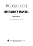
INTERCONNECTION DIAGRAM .............................................................................S-1
1
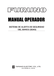
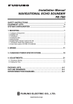
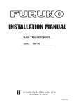
SYSTEM CONFIGURATION
Regulations require at least two SSAS alert units.
FELCOM 15
ANTENNA
UNIT
IC-115
DGPS
100/115/220/230 VAC
1φ, 50/60 Hz
AC-DC Power Supply
PR-240-CE*1
TERMINAL UNIT
IC-215
12/24
VDC
GPS receiver
OP16-24
EGC Printer
PP-50
Personal
Computer
(PC/AT compatible)
24 VDC
Printer
Shipboard LAN (Ethernet)
Printer
PP-510
24 VDC
Mini Keyboard
Distress Message Controller
DMC-5
OR
Distress Alert/
Received Call Unit
IC-305
JUNCTION
BOX
IC-315
SSAS Alert Unit
SSAS Alert Unit
IC-307
IC-307
(Max. 3 units)
CATEGORY OF UNITS
Unit
Category
Terminal Unit
Protected from weather
Antenna Unit
Exposed to weather
Other Units
Protected from weather
Alarm Unit
IC-306
Navigator
*1 Any AC-DC power supply
fulfilling requirements of
IEC 60945 may be used.
2
: Standard Supply
: Option
: Local Supply
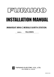
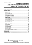
FELCOM 16
ANTENNA
UNIT
IC-116
100/115/220/230 VAC
1φ, 50/60 Hz
AC-DC
Power Supply
PR-240-CE*
PRINTER
12-24 VDC
O
POWER
I
COMMUNICATION UNIT IC-216
(with internal GPS receiver)
* Any AC-DC power supply
fulfilling requirements of
IEC 60945 may be used.
JUNCTION BOX
IC-315
SSAS ALERT UNIT
IC-307
CATEGORY OF UNITS
Antenna Unit
Exposed to Weather
Communication Unit Protected from Weather
Other Units
Protected from Weather
SSAS ALERT UNIT
IC-307
(Max. 3 units)
3
ER
RO
R
PO
W
ER
LO
G
IN
INMARSAT MINI-C MOBILE EARTH STATION
TX
FURUNO
PERSONAL
COMPUTER
(PC/AT compatible)
: Standard
: Option
: Local Supply
: SSAS only
1. OVERVIEW OF SSAS
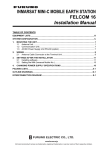
The IC-307 SSAS (Ship Security Alert System) Alert Unit connects to the Inmarsat-C MES
FELCOM 15 or the Inmarsat Mini-C FELCOM 16 for the purpose of alerting specified
addresses (for example, your ship’s company) that your ship is under attack by intruders.
The SOLAS Resolution XI-2/6 requires vessels of 500 GT or more constructed before 01
July 2004 to install an SSAS.
When your ship is under attack an SSAS report, which contains your ship’s name, MMSI
No., position, etc. is sent to up to five locations, specified by the ship’s captain or authorized
personnel. No audible or visible alarm is generated while the SSAS report is being
transmitted, to prevent discovery of the report by the intruders.
The SSAS is protected with a password to prevent unauthorized setting or testing of it by
other than the ship’s captain or authorized personnel.
Inmarsat System
Ship Name, MMSI No.,
Ship Position, etc.
Headquarters
Ship
Ship’s Company,
Management Company
4
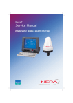
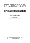
SSAS operation flow
1. Open the cover of the button and then press the button.
(This is a latch-type button; hit and release to activate the button.)
¯
2. If addresses have been preset, the SSAS report is sent to one
address 30 seconds after the button is activated.
(Max. 5 addresses)
(You may cancel transmission of the SSAS report by pressing the
button again within 30 seconds of the initial press.)
¯
3. An LES sends acknowledgement to your ship.
4. Steps 2-3 and are repeated in case of multiple addressees.
¯
5. Continuous transmission of the SSAS report begins.
(The interval at which to transmit the SSAS report to each address
can be specified. The SSAS report is continuously transmitted
while the button is ON, at the interval selected.)
¯
6. To stop transmission, press the button again to deactivate it.
(This is only possible in the SSAS manager mode. See
paragraph 3.1.)
5
2. INSTALLATION
2.1 Mounting
2.1.1 Junction box (for FELCOM 16)
The junction box IC-315 is required when installing the SSAS on the FELCOM 16; it is
already installed on the FELCOM 15.
Separate the junction box from a magnetic compass by the distances shown below to
prevent deviation to a magnetic compass.
Standard compass: 1.0 m
Steering compass: 0.7 m
1. Remove four screws from the unit to separate the cover from the unit.
2. Fix the unit to the mounting location with four self-tapping screws (4x16, supplied).
3. Connect the cables appropriately referring to paragraph 2.2.1.
120 ±0.5
70 ±0.5
Junction box IC-315
The junction box is connected to the communication unit with a 2 meter cable, with D-sub
connector (at the communication unit). Therefore, locate the junction box within two meters
of the communication unit.
6
2.1.2 SSAS alert unit
Separate the junction box from the SSAS alert unit by the distances shown below to prevent
deviation to a magnetic compass.
Standard compass: 0.70 m
Steering compass: 0.45 m
Locate the SSAS alert unit where it cannot be found by intruders. The location should be
known only by ship’s captain and authorized personnel.
Bulkhead mounting
1. Remove four screws from the unit to separate the bottom chassis from the top cover.
2. Fix the unit to the mounting location with four self-tapping screws (supplied).
3. The cable can be lead in from the bottom or the rear panel. For rear panel entrance,
change the clamp orientation as follows:
a) Unfasten three screws to remove the cable clamp.
b) Turn the clamp 90 degrees.
c) Refasten the clamp with three screws unfastened at step a) to fix the clamp.
Unfasten three screws.
Clamp
Rotate
Fasten three screws.
4. Run the cable thru one of the cable entrances and connect it to terminal board.
7
5. Attach the switch cover as shown below. Note that the cover may also be rotated 180
degrees.
Press here and hold down for five seconds.
Switch cover
Flush mounting
The optional flush mount kit OP16-28 (Code No. 004-448-010) is required.
Name
Fixture
Pan head screw
Self-tapping screw
Type
16-018-7201
M3x6
4x16
Code No.
100-317-930
000-800-362
000-802-080
Qty
1
4
4
Remarks
1. Cut out the mounting position referring to the outline drawings at the back of this
manual.
2. Fix the unit to the fixture with four pan head screws (supplied).
3. Fasten the fixture with the unit to the mounting location with four self-tapping screws
(supplied).
4. Attach switch cover as shown above.
8
2.2 Wiring
2.2.1 Junction box (for FELCOM 16)
Use the junction box IC-315 to connect the SSAS alert unit to the FELCOM 16. Unfasten
four screws to remove the cover to connect cables to terminal board. For detailed wiring
information see the interconnection diagram.
Cover
Cable clamp
(top)
Terminal
board
1 Vcc
2 GND
3 TD/RD-A
4 TD/RD-B
5 NC
6 TD-A(NAV)
7 TD-B(NAV)
8 RD-A(NAV)
9 RD-B(NAV)
10 GND
11 DMC OUT-H
12 DMC OUT-C
13 DMC IN-H
14 DMC IN-C
15 DMC CTR
IC-305/306
For connection, use the JIS cable TTYCS-4 (or equivalent, see next page for sectional view
of this cable) or the CO-SPEVV-SB-C 0.2x5P. When using the CO-SPEVV-SB-C 0.2x5P
cable, replace the cable clamp with the cable clamp 16-018-6008-1, supplied with the
junction box.
1
2
3
Core 7 mm
Communication
Unit
Cable clamp
(bottom)
Cable clamp
Procedure
1. Insert driver from direction 1 .
2. Tilt slightly toward 2 .
3. Insert cable core to 3 .
Note 1: Do not insert the cable too
deeply, to prevent pinching the sheath.
Fold back braided shield onto
sheath and fix by cable clamp.
16S0344
15mm
90mm
7mm
Junction box IC-315
9
Note 2: Pull each cable slightly to confirm that they are in their holes securely.
2.2.2 SSAS alert unit
Three SSAS alert units can be connected in series to the Junction Box IC-315. Use the
terminals on the SSAS ALERT Board 16P0229 commonly and two connector entrances. To
differentiate between units in case of multiple unit installation, change jumper block settings
as shown below, in accordance with how many units are installed.
Jumper settings for two IC-307
Unit No.1 unit*
No. 2 unit
Jumper
JP1
Yes
No
JP2
Yes
No
No. 1 unit: Unit with two cables connnected to it.
No. 2 unit: Unit with one cable connnected to it.
Two IC-307: No. 2
Three IC-307: No. 3
16P0229
JP1
1
Two IC-307: No. 1
Three IC-307: No. 1 and No. 2
Crimp-on lug to use
16P0229
JP2
2
Jumper settings for three IC-307
No. 2 unit*
No. 3 unit
*: Default Jumper Unit No.1 unit*
JP1
setting
No
No
Yes
JP2
Yes
Yes
No
No. 1 and No. 2 units: Units with two cables connnected to them.
No. 3 unit: Unit with one cable connnected to it.
JP1
3
4 5
IC-307
6
1
1: FV1.25-3, red
2: Not used.
3: FV1.25-3, red
4: FV1.25-3, red
5: FV1.25-3, red
6: Shield (FV2-3, blue)
JP2
2
3
4 5
6
IC-307
Cable Fabrication
Twist the shield.
Clamp for cable
CO-SPEVV-SB-C
0.2x5P
CO-SPEVV-SB-C 0.2X5P
or TTYCS-4
Cut unused cables.
15 mm 40 mm 10 mm
φ = 16.3 mm
Clamp for cable
TTYCS-4
or equivalent
Armor
Sheath
Shield
Conductor
S = 0.75 mm2
φ = 1.11 mm
Sectional view of cable TTYCS-4
Wiring inside the SSAS alert unit
10
2.3 Initial Settings
Set up the SSAS as follows:
1. FELCOM 15: Press [F8], [F2] to show the System Setup menu.
FELCOM 16: Press [F8], [F1] to show the System Setup menu.
2. Press [↓] to choose Command Window and then press the [Enter] key.
Command Window
RFCONCPU ***
[ Main Menu ]
1. Remote Box Setup
2. Internal GPS Setup
Enter JOB No. :
3. Type “furunoservice” (without quotation marks) in the Enter JOB No. field and then press
the [Enter] key. The prompt PASSWORD appears.
4. Enter password (see Service Manual) then press the [Enter] key. Then, the item Main
Menu is displayed in reverse video.
5. Press [1], [Enter], [1], [Enter]. One of the following windows appears.
[ DMC ]
1. SSAS
2. DMC
3. OFF
E: Exit
Enter No.:
FELCOM 15
[ SSAS ]
1. ON
2. OFF
E: Exit
Enter No.:
FELCOM 16
6. Press [1], [Enter]. This enables the SSAS functions.
7. Press the [Esc] key several times to close the menu.
Note: Test the SSAS button and SSAS report for proper operation, referring to paragraphs
3.4 and 3.5, respectively.
11
3. OPERATION
3.1 Operation Mode
There are two menu operating modes:
Normal mode:
Menus other than SSAS-related menus are displayed.
SSAS manager mode: The mode is activated by the password entered by the ship’s
captain or authorized personnel. The indication “SSAS Manager
Mode” is shown flashing at the top of the screen when this mode is
activated. All SSAS-related menus are available. Transmission of
the SSAS report may be cancelled in this mode. The equipment
starts up in the normal mode, regardless of the mode in use when
the power is turned off.
3.1.1 Changing the password
The default password is “ship security alert”. Ship’s captain or authorized personnel may
change the password as follows:
1. FELCOM 15: Press [F8], [F2] to show the System Setup menu.
FELCOM 16: Press [F8], [F1] to show the System Setup menu.
2. Press [↓] to choose Command Window and then press the [Enter] key.
Command Window
RFCONCPU ***
[ Main Menu ]
1. Remote Box Setup
2. Internal GPS Setup
Enter JOB No. :
3. On the Enter JOB No. field, type “ssas password” (without quotation marks) and then
press the [Enter] key. The prompt OLD PASSWORD appears.
4. Type your current password and then press the [Enter] key. The prompt NEW
PASSWORD appears.
5. Enter new password, using at least six characters, and then press the [Enter] key. The
prompt RETYPE NEW PASSWORD appears.
Note: If less than six characters are entered for the password, the message “Please
use a longer password.” appears. Enter a longer password.
6. Enter new password again and then press the [Enter] key. The message “Password
changed” appears.
7. Press the [Esc] key several times to close the menu.
Note: The SSAS manager mode cannot be unlocked without the proper password.
12
3.1.2 SSAS manager mode
All SSAS-related settings are set in the SSAS manager mode. Do the following to access
this mode.
1. FELCOM 15: Press [F8], [F2] to show the System Setup menu.
FELCOM 16: Press [F8], [F1] to show the System Setup menu.
2. Press [↓] to choose Command Window and then press the [Enter] key.
Command Window
RFCONCPU ***
[ Main Menu ]
1. Remote Box Setup
2. Internal GPS Setup
Enter JOB No. :
3. On the Enter JOB No. field, type “ssas manager” (without the quotation marks) and then
press the [Enter] key.
4. Type password and then press the [Enter] key. The window below appears; you are now
in the SSAS manager mode.
CAUTION
04-04-20 05:37 (UTC)
SSAS Manager Mode enabled.
<Press ESC key to continue>
5. Press the [Esc] key several times to close the menu. This enables the SSAS manager
mode, which allows you to execute the procedure in paragraph 3.2.
13
3.2 Setting SSAS Report Destination and
Message Contents
When the SSAS is activated, the SSAS report is sent according to the addresses (max. 5)
and message content set with SSAS Report 1 – SSAS Report 5 on the SSAS Report menu.
Note 1: The destination and message content of an SSAS report varies according to
Administration. Therefore, set them as requested by ship’s authorities. For
information other than ship’s name, MMSI no. and IMN no., set it manually with
“Other Inf.”
Note 2: The equipment must be in the SSAS manager mode to execute this procedure.
See paragraph 3.1.2.
1. Press the [F5] to open the Reports menu.
Reports
1. Data Report
2. Message Report
3. Data Network ID
4. SSAS Report
2. Press the [4] key to shown the SSAS Report menu.
SSAS Report
1. SSAS Report 1
2. SSAS Report 2
3. SSAS Report 3
4. SSAS Report 4
5. SSAS Report 5
6. Message Contents
3. Press [1], [2], [3], [4] or [5] key as appropriate. (When the button is tested, a test report is
sent to the address specified for the youngest SSAS report number. Therefore, set the
address which is to receive the test report set for the youngest SSAS report number.)
SSAS Report
Status
Station Name
Destination Type
Prefix Code
Country/Ocean Code
Station ID
Modem Type
Address
Subject
LES ID
Report Interval
ON
TELEX
02:00 (hh: mm)
4. Press the [↓] key to choose Station Name and then press the [Enter] key.
5. Press the [↑] or [↓] key to choose appropriate station and then press the [Enter] key.
You may sort the list by group name, station name or communication type as follows:
Group name: Each press of [Ctrl] + [G] sorts the list by group name, ascending
or descending order.
Station name: Each press of [Ctrl] + [N] sorts the list by station name, in
ascending or descending order.
Comm. type: Each press of [Ctrl] + [T] sorts the list by communication type, in
ascending or descending order.
14
6.
7.
8.
9.
Press the [↓] key to choose LES ID and then press the [Enter] key.
Press the [↑] or [↓] key to choose LES and then press the [Enter] key.
Press the [↓] key to choose Report Interval and then press the [Enter] key.
Enter time interval (00:10-99:59) to transmit the SSAS report and then press the [Enter]
key.
Note: After the SSAS report is transmitted and the button remains “ON” (
report is transmitted at the interval set here.
), the SSAS
10. Press the [Esc] key to open the Update window.
Status
Station Name
Destination Type
Prefix Code
Country/Ocean Code
Station ID
Modem Type
Address
Subject
LES ID
Report Interval
SSAS Report
ON
TELEX
Update
Yes
No
02:00 (hh: mm)
11. Yes is selected; press the [Enter] key to close the SSAS report window.
12. Press the [6] key to display the SSAS Message Contents menu.
Vessel Name :
MMSI
:
IMN
:
Other Inf.
:
LAT:
LON:
Time:
COURSE:
SPEED:
Time:
SSAS Message Contents
______________________________
_________
_________
_______________________________________________________
_______________________________________________________
_______________________________________________________
34: 44. 46N
135: 21. 26E
02/04/2004 04:31:48 (UTC)
071 deg
00 kt
02/04/2004 04:31:48 (UTC)
13. Press the [Enter] key to open the Vessel Name window.
14. Enter vessel’s name and then press the [Enter] key.
15. Press the [↓] key to choose MMSI and then press the [Enter] key.
16. Enter MMSI number and then press the [Enter] key.
17. Press the [↓] key to choose IMN and then press the [Enter] key.
18. Enter IMN and then press the [Enter] key.
19. Press the [↓] key to choose Other Inf. and then press the [Enter] key
20. Enter appropriate message (three lines) and then press the [Enter] key.
Note: To shift between lines, use the [↑] or [↓] key.
21. Press the [Esc] key to display the Update window.
22. Yes is selected; press the [Enter] key to close the SSAS Message Contents menu.
15
23. Press the [Esc] key twice to return to the standby display.
Note 1: To delete entered subscriber’s data, choose “Remove” from “Status.”
Note 2: SSAS report settings may be saved to a floppy disk for backup.
FELCOM 15: [F8], [9], [6] to show the Save/Load window.
FELCOM 16: [F8], [8], [6] to show the Save/Load window.
Save to FD
1. ALL
2. Station List
3. LES List
4. E-Mail Service List
5. SSAS Report*
6. Other
Load from FD
1. ALL
2. Station List
3. LES List
4. E-Mail Service List
5. SSAS Report*
6. Other
*: Availlable only in SSAS manager mode
("5.SSAS Report" is added in the SSAS
manager mode and item numbers are shifted.)
Note 3: To confirm the settings, follow paragraph 3.5.
16
3.3 Transmitting SSAS Report
In the normal mode, the SSAS report is sent 30 seconds after the button on the SSAS is
pressed. The SSAS repeatedly transmits the report even if the button is pushed off ( ).
Repeated transmission can only be stopped from the SSAS manager mode.
1. Open the cover of the SSAS alert button.
Cover
2. Push the button. The button is a latch-type button; hit and release the button to activate
( ) the SSAS unit.
3. The SSAS report is transmitted 30 seconds after the button is pushed in ( ). Below are
the contents of the SSAS report.
- - - SSAS ALERT MESSAGE - - Vessel Name: Queen Elizabeth 2
MMSI:
111660000
IMN:
443100000
Help me!
LAT:
34:44.46N
LON:
135:21.26E
Time:
02/04/2004 04:31:48 (UTC)
COURSE:
071 deg
SPEED:
00 kt
Time:
02/04/2004 04:31:48 (UTC)
Ship’s Name
MMSI No.
IMN No.
Desired message
Own ship postion in latitude
Own ship position in longitude
Time of position data
Course
Speed
Time of course and speed data
Note: If you accidentally push the button in, push it again within 30 seconds to cancel
the report. The button pops out ( ) and the report is not transmitted. When this
is done, the message “INF: SSAS UNIT activation has been canceled.” appears
on the display. Additionally, for the FELCOM 16, the POWER lamp on the
communication unit flashes 30 seconds.
4.
5.
6.
7.
An LES sends acknowledgement to your ship.
For multiple destinations, steps 3 and 4 are repeated.
The SSAS report is transmitted repeatedly while the button remains pushed in ( ).
To stop transmission, push the button again to pop it out ( ). (SSAS manager mode
only.)
17
Note 1: You may cancel repeated transmission from either operating mode by pushing the
button OFF→ON→OFF→ON→OFF. You must allow no more than three seconds
to elapse before pushing the button again. If more than three seconds elapses,
repeat the procedure. When transmission is stopped, the message “INF: SSAS
UNIT activation has been cancelled.” appears and, on the FELCOM 16 only, the
POWER lamp on the communication unit flashes approx. 30 seconds.
Note 2: If transmission is not canceled with the button and the power is turned off, the
equipment resumes repeated transmission when powered again.
18
3.4 Testing the Button
The SSAS buttons can be tested as below.
Note 1: An actual SSAS report cannot be transmitted during the testing.
Note 2: The equipment must be in the SSAS manager mode to conduct the test.
FELCOM 15
1. Press the [F7] key to display the Options menu.
2. Press the [7] key ([6] key when the FELCOM functions as an EGC receiver) to display
the Test menu.
Test
1. PV Test
2. PV Test Result
3. Diagnostic Test
4. Distress/SSAS Button Test
3. Press the [4] key.
Options
Test
1. Login
2.1.Logout
PV Test Distress/SSAS Button Test
3.2.Abort
PV Test Result
Start
4.3.Select
NCS
Self Test
5.4.Ocean
Region
Distress
Alarm Button Test
No
Yes
6. Test
4. Press the [Enter] key to start the test.
Options
Test
1. Login
2.1.Logout
PV Test Distress/SSAS Button Test
3.2.Abort
PV Test Result
4.3.Select
NCS
Distress/SSAS
buttons are under test mode.
Self
Test
CAUTION
5.4.Ocean
Region
Press
any key
to escape.
Distress
Alarm
Button
Test
INF: Distress/SSAS
Buttons entered into TEST MODE.
6. Test
<Press ESC key to continue>
The display shows the message (in red) “Distress/SSAS buttons are under test. Cancel
the test mode if a real distress/SSAS needs to sent.” appears.
5. Open the button cover on the No.1 SSAS.
6. Push the button in ( ). The CAUTION window displays the message “SSAS UNIT
works correctly.” appears if the unit is functioning properly.
Note: 30 seconds after step 6, the SSAS test report is automatically sent. If you do not
need to send the SSAS report, go to step 8 within 30 seconds.
7. The SSAS test report is automatically sent once to the address specified for the
youngest SSAS report number (1-5).
8. Turn the button of the No. 1 SSAS off ( ).
Note: To test the No. 2 and No. 3 SSAS repeat steps 6-8.
19
9. To escape from the test, press the [Esc] key twice on the terminal unit. The test mode is
stopped and the message shown below appears to notify you that normal operation has
been restored.
CAUTION
INF: Distress/SSAS Buttons returned to NORMAL OPERATION.
<Press ESC key to continue>
Further, because the button remains pushed in (
SSAS button into OFF-STATE.” appears.
), the message “Please return the
10. Push the button again to pop it out ( ).
11. Close the button cover.
12. Press the [Esc] key three times to return to the standby display.
Note: If the button is left pushed in ( ) when the terminal unit is turned on, the equipment
displays “Please return the SSAS button into OFF-STATE.” Push the button again to
turn off ( ) the button.
FELCOM 16 (no PC)
1.
2.
3.
4.
Turn off the communication unit.
Push the button of the No. 1 SSAS to turn it on ( ).
Turn on the communication unit.
30 seconds later the POWER, LOGIN and TX LEDs on the communication unit start
flashing together if the button is judged to be ON.
Note: An SSAS test report is automatically transmitted 30 seconds after all LEDs start
flashing at step 4. If you do not need to send the test report, skip to step 7.
5. 30 seconds after LEDs start flashing the SSAS test report is sent once to the address
specified for the youngest SSAS report number (1-5). At this time the LEDs flash rapidly.
If transmission was successful the LEDs mentioned in step 4 flash slowly. If transmission
failed, only the ERROR LED flashes (rapidly).
6. Push the button of the No. 1 SSAS to turn it off ( ). The LEDs light in order of POWER,
LOGIN, TX, POWER, LOGIN, TX.
7. Push the button of the No. 2 SSAS to turn it on ( ).
8. 30 seconds later the POWER, LOGIN and TX LEDs on the communication unit start
flashing together if the button is judged to be ON.
Note: An SSAS test report is automatically transmitted 30 seconds after all LEDs start
flashing. If you do not need to send the test report, skip to step 10.
9. 30 seconds after the above-mentioned LEDs start flashing the SSAS test report is sent.
10. Push the button of the No. 2 SSAS to turn it off ( ).
Note: If there is a No.3 SSAS, test it by following steps 7-10.
11. Finally, turn the communication unit off and then on again.
Note 1: After completing the testing, be sure to turn off all SSAS units.
Note 2: The normal mode is automatically restored after 60 minutes elapses in the test
mode.
20
Note 3: The ERROR LED flashes every two seconds if the button of an SSAS stays on for
more than 10 seconds. It also flashes when the equipment switches to the normal
mode (see Note 2). Turn off the button to stop the LED from flashing.
FELCOM 16 (by PC)
1. Press the [F7] key to display the Options menu.
2. Press the [7] key ([6] key when the FELCOM functions as an EGC receiver) to display
the Test menu.
Test
1. PV Test
2. PV Test Result
3. Diagnostic Test
4. SSAS Button Test
3. Press the [4] key.
Options
Test
1. Login
SSAS Button Test
2.1.Logout
PV Test
3.2.Abort
PV Test Result
Start
4.3.Select
NCS
Self Test
5.4.Ocean
Region
Distress
Alarm Button Test
No
Yes
6. Test
4. Press the [Enter] key to start the test.
Options
Test
1. Login
SSAS Button Test
2.1.Logout
PV Test
3.2.Abort
PV Test Result
4.3.Select
NCS
SSAS buttons are under test mode.
Self Test
CAUTION
5.4.Ocean
Region
Press
any key
to escape.
Distress
Alarm
Button
Test
INF: SSAS6.Buttons
Test entered into TEST MODE.
<Press ESC key to continue>
The display shows the message (in red) “SSAS buttons are under test. Cancel the test
mode if a real SSAS alert needs to sent.” appears.
5. Open the button cover on the No. 1 SSAS.
6. Push the button in (ON). The CAUTION window displays the message “SSAS UNIT
works correctly.” appears if the unit is functioning properly.
Note: 30 seconds after step 6, the SSAS test report is automatically sent. If you do not
need to send the test report, go to step 8 within 30 seconds.
7. The SSAS test report is automatically sent once to the address specified for the
youngest SSAS report number (1-5).
8. Turn the button of the No. 1 SSAS off ( ).
Note: To test the No. 2 and No. 3 SSAS repeat steps 6-8.
21
9. To escape from the test, press the [Esc] key twice on the terminal unit. The test mode is
stopped and the message shown below appears to notify you that normal operation has
been restored.
CAUTION
INF: SSAS Buttons returned to NORMAL OPERATION.
<Press ESC key to continue>
Further, because the button remains pushed in (
SSAS button into OFF-STATE.” appears.
), the message “Please return the
10. Push the button again to pop it out ( ).
11. Close the button cover.
12. Press the [Esc] key three times to return to the standby display.
Note: If the button is left pushed in ( ) when the communication unit is turned on, the
equipment will go into the test mode if the SSAS is not transmitting repeatedly. To
return to the standby display, push the button again to pop it out ( ) and then turn
the communication unit off and on again.
22
3.5 SSAS Report Test
You can test for successful transmission of the SSAS report to the address you specify,
without using the button. The test report message states “!!! Test Call !!!” to alert the
receiver of the message that it is a test call.
1. Press the [F5] key to open the Reports menu.
2. Press the [4] key to choose the SSAS Report menu.
3. Press the [1], [2], [3], [4] or [5] key as appropriate, and the SSAS report setting menu
appears.
4. Set destination where to transmit the test.
5. Press the [↑] key to choose Status and then press the [Enter] key.
6. Press the [↓] key to choose TEST and then press the [Enter] key.
7. Press the [Esc] key to show the Update window.
8. Yes is selected; press the [Enter] key. The test report is transmitted. After it is
transmitted, “Status” is automatically set to ON.
9. Press the [Esc] key twice to return to the standby display.
23
D-1
Y. Hatai
署名は
検証さ
れてい
ません
。
Yoshitosh
i Hatai
電子署名者 : Yoshitoshi
Hatai
DN: cn=Yoshitoshi
Hatai, o=Furuno, c=JP
日付 : 2004.04.16
12:53:57 +09'00'
D-2
Takahashi T.
Y. Hatai
署名は
検証さ
れてい
ません
。
Yoshitosh
i Hatai
電子署名者 : Yoshitoshi
Hatai
DN: cn=Yoshitoshi
Hatai, o=Furuno, c=JP
日付 : 2004.04.16
12:53:57 +09'00'
Y. Hatai
署名は
検証さ
れてい
ません
。
Yoshitosh
i Hatai
電子署名者 : Yoshitoshi
Hatai
DN: cn=Yoshitoshi
Hatai, o=Furuno, c=JP
日付 : 2004.04.16
12:53:57 +09'00'
D-3
1
2
アンテナユニット
ANTENNA UNIT
IC-115
ケーブル:コネクタ、選択
CABLE: CONNECTOR, SELECTED
TPA5FB0.3NJ5
FBA-5DFB,0.3m
12D-SFA-CV,100m,φ15.6: N-P-120DSFA
8D-FB-CV,50m,φ11.0: N-P-8DFB
4
ターミナルユニット
TERMINAL UNIT
IC-215
TNCP-NJ
GND
RW-4747
0.3m
3
DGPS
BNC PLAG
5
P
*2
CO-AX (50Ω)
DGPSデコーダー
DGPS DECODER
P
A
2B02
キーボード
KEYBOARD
BTC-5100C PS/2
B
LAN(HUB) OR PC, ETC.
1
2
3
4
5
6
P
*3
*1
57-3036
1
E_TD_P
E_TD-N
E_RD_P
NC
NC
E_RD_N
NC
NC
36
MJ-A3SPF0018,5m,φ11
12-24 VDC
100-115/
220-230 VAC
1φ,50/60Hz
24 VDC
*2
DPYC-2.5
φ12.8
*2
DPYC-4
φ13.9
1
2
3
4
5
6
7
8
9
10
11
12
13
14
15
ダイ
ORG
アオ
BLU
キ
YEL
クロ
BLK
モモ
PNK
アオ/アカ1 BLU/RED1
シロ
WHT
ダイ/シロ1 ORG/WHT1
ミドリ/シロ1 GRN/WHT1
ムラサキ
PPL
*2
TTYCS-4,φ16.3
P
P
CO-0.2x2P
航法装置
NAV EQUIPMENT
TXD-H
TXD-C
DMC_OUT-H
DMC_OUT-C
DMC_IN-H
DMC_IN-C
DMC_CTR
P
P
FITTED AT FACTORY.
SHIPYARD SUPPLY.
OPTION.
GROUND THRU CONNECTOR CLAMP.
USER SUPPLY.
TB BOARD (16P0116) REQUIRED.
2 OR 3 SETS CAN BE CONNECTED.
CHANGE JUMPER SETTING IN LAST IC-307.
保安警報発呼器
SSAS ALERT UNIT
IC-307 (No.2)
*3 *7
TB
1 SSAS_OUT-H
2 NC
3 SSAS_CHECK
4 SSAS_IN-C
5 SSAS_CTRL
6 GND
保安警報発呼器
SSAS ALERT UNIT
IC-307 (No.3)
*3 *7
TB
1 SSAS_OUT-H
2 NC
3 SSAS_CHECK
4 SSAS_IN-C
5 SSAS_CTRL
6 GND
*2
TTYCS-4,φ16.3 OR CO-0.2x5P
合計 :最大200m
TOTAL:MAX.200m
遭難警報装置 DMC-5
DISTRESS MESSAGE
CONTROLLER
*2
TB5
TTYCS-4,φ16.3
1 DIST_IN-H
P
2 DIST_IN-C
3 DIST_OUT-H
P
4 DIST_OUT-C
5 DIST_CTR
6 GND
25
DTE
16P0209
TXD
RXD
FUSE
15A(12V)
12-24VDC
MJ-A3SPFD
7A(24V)
1 DC(+)
シロ WHT
2 DC(-)
クロ BLK
3 GND
GND
16P0214
D-sub9P
1
2
3
4
5
6
7
8
9
*4
*3
17JE-573-10,5m,φ8
CO-0.2x5P,15m MAX.
D-sub9P
パソコン
NC PC
RXD
TXD
DTR
S.GND
DSR
RTS
CTS
NC
1
2
3
4
5
6
7
8
9
CO-0.2x2P *3
15m MAX.
*5
*4
FM14-7P
PR-240-CE
+ 24VDC AC/DC電源ユニット
- INPUT AC/DC POWER
SUPPLY UNIT
注記
*1)工場にて取付済み。
*2)造船所手配。
*3)オプション。
*4)コネクタクランプでアースに落とす。
*5)ユーザー手配。
*6)TB基板(16P0116)が必要。
*7)2台または3台接続可能。
終端のIC-307はジャンパー設定の変更が必要。
遭難警報器 IC-305
DISTRESS ALERT/
RECEIVED CALL UNIT
16P0213A
1 VCC
2 GND
3 TD/RD-A
4 TD/RD-B
5 FG
保安警報発呼器
SSAS ALERT UNIT
IC-307 (No.1)
*3 *7
TB
1 SSAS_OUT-H
2 NC
3 SSAS_CHECK
4 SSAS_IN-C
5 SSAS_CTRL
6 GND
*4
24VDC +
*3 OUTPUT -
PE,IV-1.5SQ.
保護アース
NOTE
*1.
*2.
*3.
*4.
*5.
*6.
*7.
16S0344,2m,φ9.2
チャ
BRN
ミドリ GRN
アカ
RED
ハイ
GRY
*4
2B10
AC_IN
1
2
3
4
5
6
7
8
9
10
11
12
13
14
15
PRINTER
2B03
C
D-sub15P
JUNCTION
Vcc(ALM)
GND
TD/RD-A
TD/RD-B
NC
TD-A
TD-B
RD-A
RD-B
GND
DMC_OUT-H
DMC_OUT-C
DMC_CHECK
DMC_IN-C
DMC_CTRL
接続箱
JUNCTION BOX
IC-315
1
*4
D
1
2
3
4
5
6
7
8
17JE-23250
-02(D8C) *1
16S0184,3m,φ8
24 VDC
VCTF-0.75x3C
5m,φ6.9
(16S0084)
プリンタ
PRINTER
PP-510
KDAT
NC
GND
+5V
KCLK
NC
LAN
RJ-45
P
24VDC
J1
RH12BPG-3S
1 +24V
アカ RED
2 0V
クロ BLK
3 GND
シロ WHT
16P0208A
KEYBOARD
*5
Ethernet CABLE
PC: CROSS CABLE
HUB: STRAIGHT CABLE
アラームユニットIC-306
ALARM UNIT
16P0213B
1 VCC
2 GND
3 TD/RD-A
4 TD/RD-B
5 FG
ANT
TP5FBAW-5DFBB,30m,φ7.6
船内LAN (HUB)
パソコンなど
S-1
6
GND 銅板
W=30 COPPER STRAP
05-003-0031,1.2m
*3
FM14-7P
CO-0.2x5P
1
MAX.100m
2
FM14-5P
1
2
3
4
5
RXD
TXD
NC
NC
0V
I/F BOX
OP16-14 *3
DRAWN
Apr. 15 '04
CHECKED
3
4
5
6
7
CO-0.2x2P: CO-SPEVV-SB-C 0.2x5P,φ10.5
CO-0.2x5P: CO-SPEVV-SB-C 0.2x5P,φ13.5
SCALE
7
NC
1
2
3
4
5
6
7
RXD-H
TXD-H
FG
TXD-C
RXD-C
+9V
NC
EGCプリンタ
EGC PRINTER
PP-505
*3
1
2
(+)
(-)
P
24VDC
EGCプリンタ
EGC PRINTER
PP-505 *3 *6
(+)
(-)
1
2
08S0157,3m
24VDC
GND
08S0087
名称
FELCOM 15
インマルサットC船舶地球局
相互結線図
Y. Hatai
MASS
C5635-C01- E
08S0157,3m
GND
08S0087
TITLE
K.MIYAZAWA
kg
DWG No.
RXD
TXD
0V
FM14-7P
P
TAKAHASHI.T
APPROVED
1
2
3
NAME
INMARSAT-C MES
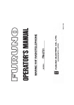
INTERCONNECTION DIAGRAM
FURUNO ELECTRIC CO., LTD.
署名は
検証さ
れてい
ません
。
Yoshitosh
i Hatai
電子署名者 : Yoshitoshi
Hatai
DN: cn=Yoshitoshi
Hatai, o=Furuno, c=JP
日付 : 2004.04.16
12:53:57 +09'00'
C
B
A
TNCP-NJ
PR-240-CE
AC/DC電源ユニット
AC/DC POWER
SUPPLY UNIT
+ 24VDC
- INPUT
注記
*1)工場にて取付済み。
*2)造船所手配。
*3)オプション。
*4)コネクタクランプでアースに落とす。
*5)ユーザー手配。
*6)SSAS仕様。
*7)最大3台まで接続可能。
終端のIC-307はジャンパー設定の変更が必要。
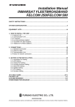
NOTE
*1. FITTED AT FACTORY.
*2. SHIPYARD SUPPLY.
*3. OPTION.
*4. GROUND THRU CONNECTOR CLAMP.
*5. USER SUPPLY.
*6. SSAS SPECIFICATION.
*7. MAX 3 SETS CAN BE CONNECTED.
CHANGE JUMPER SETTING IN LAST IC-307.
PE,IV-1.5SQ.
保護アース
24VDC +
*3 OUTPUT -
AC_IN
APPROVED
DWG No.
SCALE
1
2
3
4
5
6
7
8
9
10
11
12
13
14
15
1
2
3
4
5
6
7
8
9
*4
TAKAHASHI.T
C5638-C01- D
MASS
kg
ダイ
ORG
アオ
BLU
キ
YEL
クロ
BLK
モモ
PNK
アオ/アカ1 BLU/RED1
シロ
WHT
ダイ/シロ1 ORG/WHT1
ミドリ/シロ1 GRN/WHT1
ムラサキ
PPL
K.MIYAZAWA
Y. Hatai
3
*6
*3
17JE-573-10,5m,φ8
16S0344
2m,φ9.2
チャ
BRN
ミドリ GRN
アカ
RED
ハイ
GRY
D-sub15P
*4
D-sub9P
GND 銅板
W=30 COPPER STRAP
05-003-0031,1.2m
SSAS_CHECK
SSAS_IN-C
SSAS_CTRL
DRAWN
Apr. 21 '04
CHECKED
2B10 16P0227
Vcc(6.5V)
GND
TX/RX-A
TX/RX-B
SSAS
GND
SSAS_OUT-H
2B02 16P0208B
ANT
TXD
RXD
DTE
通信制御ユニット
COMMUNICATION UNIT
IC-216
2
FUSE
12VDC:10A
*1
12-24VDC
FM-C3FP
24VDC: 5A
1 DC(+)
アカ RED
2 DC(-)
クロ BLK
3 GND
TP5FBAW-5DFBB,30m,φ7.6
TP58A15W-RG58,15m,φ5.0
12D-SFA-CV,100m,φ15.6: N-P-120DSFA
8D-FB-CV,50m,φ11.0: N-P-8DFB
ケーブル:コネクタ、選択
CABLE: CONNECTOR, SELECTED
P16-6-3.5(3P),3.5m,φ7.5
TPA5FB0.3NJ5
FBA-5DFB,0.3m
100-115/
*2
220-230 VAC DPYC-2.5
1φ,50/60Hz φ12.8
*2
DPYC-4
24 VDC
φ13.9
12-24 VDC
GND
RW-4747
0.37m
アンテナユニット
ANTENNA UNIT
IC-116
1
1
2
3
4
5
6
7
8
9
P
NC
RXD
TXD
DTR
S.GND
DSR
RTS
CTS
NC
P
パソコン
PC
*5
保安警報発呼器
SSAS ALERT UNIT
IC-307 (No.1)
TB
1 SSAS_OUT-H
2 NC
3 SSAS_CHECK
4 SSAS_IN-C
5 SSAS_CTRL
6 GND
*6
NAME
名称
TITLE
保安警報発呼器
SSAS ALERT UNIT
IC-307 (No.2)
TB
1 SSAS_OUT-H
2 NC
3 SSAS_CHECK
4 SSAS_IN-C
5 SSAS_CTRL
6 GND
*6
INTERCONNECTION DIAGRAM
INMARSAT-C MES
相互結線図
FELCOM 16
インマルサットC船舶地球局
*6 *2 TTYCS-4,φ16.3 OR CO-0.2x5P
全長200m以下 TOTAL:200m MAX.
接続箱
JUNCTION BOX
IC-315
*6
1 Vcc
2 GND
3 TD/RD-A
4 TD/RD-B
5 NC
6 TD-A
7 TD-B
8 RD-A
9 RD-B
10 GND
11 DMC_OUT-H
12 DMC_OUT-C
13 DMC_IN-H
14 DMC_IN-C
15 DMC_CTR
*4
D-sub9P
4
保安警報発呼器
SSAS ALERT UNIT
IC-307 (No.3)
TB
1 SSAS_OUT-H
2 NC
3 SSAS_CHECK
4 SSAS_IN-C
5 SSAS_CTRL
6 GND
*6 *3 *7
署名は
検証さ
れてい
ません
。
電子署名者 : Yoshitoshi
Hatai
DN: cn=Yoshitoshi
Hatai, o=Furuno, c=JP
日付 : 2004.04.16
12:53:57 +09'00'
Yoshitosh
i Hatai
S-2
Your Local Agent/Dealer
9-52 Ashihara-cho,
Nishinomiya, Japan
Telephone :
0798-65-2111
fax
0798-65-4200
:
All rights reserved.
Printed in Japan
PUB.No. OME-56351
( DAMI ) IC-307
FIRST EDITION : MAY. 2004
*00015035900*
*00015035900*
*00015035900*
*OME56351A00*
*OME56351A00*
*OME56351A00*