1
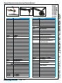
DESCRIPTION
591100
SCREW
591106
SET SCREW (SPECIFY SPEED)
592016
SNAP RING
594016
0-RING
832636
GASKET
841552
3/8 NPT TO 3/8 NPT BUSHING
841553
3/8 NPT TO 1/4 NPT BUSHING
844302
0-RING
869311
THROTTLE VALVE CAP
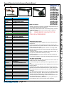
ACCESSORIES
PART NUMBER
DESCRIPTION
400-78
3/8-24 TO 5/8-11 ADAPTER
405-24
BACKING PLATE FOR 490-KR
490-K
3/8-24 X .980 TYPE 27 ADAPTER
ASSY.
490-KR
3/8-24 X .580 TYPE 27 ADAPTER
ASSY.
490-1
BACKING PLATE FOR 490-K
490-2
NUT FOR 490-K & 490-KR
1100-660
3/8-24 TO 5/8 I.D. TYPE 27
ADAPTER ASSY.
1100-661
3/8-24 TO 5/81.D. BACKING PLATE
1100-662
3/8-24 TO 5/8 I.D. ADAPTER NUT
1100-664
3/8-24 TO 7/8 I.D. BACKING PLATE
1100-666
3/8-24 TO 7/8 I.D. ADAPTER NUT
1100-668
3/8-24 TO 7/8 I.D. TYPE 27
ADAPTER ASSY.
1100-692
5/8-11 TO 7/8 I.D. TYPE 27
ADAPTER ASSY.
1100-694
5/8-11 TO 7/8 I.D. BACKING PLATE
1100-696
5/8-11 TO 7/8 I.D. ADAPTER NUT
849259
5/8-11 SANDING PAD NUT
849259-A
3/8-24 SANDING PAD NUT
889271
5/8-11 4” SANDING PAD
(MAX 12000 RPM)
889271-A
3/8-24 4” SANDING PAD
(MAX 12000 RPM)
849848
5/8-11 5” SANDING PAD
(MAX 10000 RPM)
849913
5/8-11 7” SANDING PAD
(MAX 8500 RPM)
www.HenryTools.com | Page 103
SAFETY (continued)
clothing. Continuous exposure to vibration may cause injury to
your hands and arms.(See regulations.)
10.Properly maintained air tools are less likely to fail or cause
accidents. If tool produces an unusual sound or vibrations
repair immediately.
11.
NEVER MODIFY ANY PART OF THE
TOOL OR ACCESSORIES!!
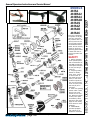
Disassembly First Steps
1. Disconnect tool from air supply and remove all wheels and
accessories.
2. Secure the tool in an aluminum jawed vise vertically with
angle head toward the upward direction. Clamp onto flats of the
motor housing (402-132).
3. Unscrew lock nut (406-38) with a wrench. The angle head
assembly will disconnect from motor housing. Set angle head
assembly aside.
4. Remove coupling (406-41), exhaust sleeve (410-G-17S), oring (400-51) and exhaust screen (402-134).
5. Unscrew and remove motor retainer (406-39) carefully on
flats with wrench.
6. Pull motor assembly out of motor housing. Remove from vise.
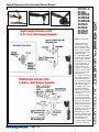
The Motor Disassembly
7. Remove snap ring (404-39) if present from rear of motor assembly with use of snap ring pliers.
8. Lift out bearing cover (404-38) and o-ring (594016) if present.
9. Remove snap ring (592016) out of spindle groove with use of
snap ring pliers.
10. Secure the motor assembly vertically in the vise with the
geared end toward the downward direction. Lightly clamp onto
the outside diameter of cylinder (400-2G) and rear endplate
(404-19).
11. Lightly tap the spindle (406-14) out of rear bearing (404-9)
with use of a 3/16” punch. Be sure not to drop the front motor
assembly when it becomes free. Remove from vise.
12. Push or tap the rear bearing out of the read endplate with
use of a small punch or screwdriver.
13. Remove rotor (400-5), blades (400-6), key (400-10) and
front endplate (400-7) from the front motor assembly.
For additional product information visit our website.
Revised 02/19/12
Ph:
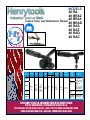
PART NUMBER
MODELS
48 RA
48 BRA2
48 BRA4
48 BRAD
48 RAS
48 RAZ
48 RAD
48 RAC
HENRY TOOLS, INC. (216) 291-1011 or (800) 826-5257
General Operators Instructions and Service Manual