1
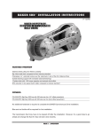
Install at ion Instr uct ions INSTALLATION INSTRUCTIONS over view V.031407 BAKER FUNCTION FORMED PRIMARY FEATURES • • • • • • • • ALL BILLET 6061-T6 AIRCRAFT GRADE ALUMINUM CONSTRUCTION One piece STARTER jackshaft (INCLUDED) High torque inner primary bearing POLISHED Stainless steel fasteners eXTERNALLY ADJUSTABLE CHAIN TENSIONER WITH UPPER RUNG ACCESS COVER COMPATIBLE WITH ALL HARLEY SOFTAIL CLUTCHES, COMPENSATING SPROCKETS, STARTERS AND BAKER EQUIVALENT AVAILABLE IN SHOW PolishED or black anodized finish OPTIONAL UPGRADE TO KING KONG KLUTCH WITH INTERNAL BEARING SUPPORT � PART NUMBERS AND APPLICATIONS: 4100P-FFP-E 4100B-FFP-E 4100P-FFP-L 4100B-FFP-L 1990-93 sOFTAIL WITH 66 TOOTH CLUTCH RING GEAR, SHOW POLISHED 1990-93 SOFTAIL WITH 66 TOOTH CLUTCH RING GEAR, BLACK ANODIZED 1994-2006 SOFTAIL WITH 102 TOOTH CLUTCH RING GEAR, SHOW POLISHED 1994-2006 SOFTAIL WITH 102 TOOTH CLUTCH RING GEAR, BLACK ANODIZED PAGE 1 | OVERVIEW b aker FUNCTION FORMED PRIMARY installation: table of contents: 1. Overview 2. Table of Contents 3. Included Parts Illustration 4. Included Parts Detail 5. Skills, Knowledge & Tools 6. Stock Bike Disassembly 7-9. Step by step installation 10. Terms 11. Disclaimer PAGE 2 | TABLE OF CONTENTS i nclu ded part s 26. 27. 2. 22. 6. 24. 18. 21. 40. 41. 23. 39. 7. 24. 1. 24. 3. 5. 34. 30. 4. 10. 24. 31. 25. 11. 8. 17. 9. 28. 38. 33. 16. 28. 14. 37. 28. 12. 36. 15. 42. PAGE 3 | PARTS 13. 29. i nclu ded part s # Part Number 1 4004-FFP 2 4003-FFP 3 4005-FFP 4 4006-FFP 5 4007-FFP 6 4008-FFP 7 4010-FFP 8 4012-FFP 9 4013-FFP 10 4009-FFP 11 4014-FFP 12 243-56 13 S4446-004 14 S4946-001 15 19601 16 56FFNNEOZ 17 9452K58 18 9452K78 19 93615A410 20 93615A415 21 25C075KCSSP 22 25C125KCSSP 23 25C175KCSSP 24 26749 25 98381A593 26 4001-FFP 27 4000-FFP 28 99142A350 29 99142A590 30 12035B 31 205SFF 32 9758 33 51740 34PAPZ2525 35 4011-FFP 36 31C225KCSOB 37 31C200KCSOB 38 31C100KCSOB 39 9452K132 40 92210A535 41 93615A410 42 37KKPD Quantity Description 1 Inner Primary 1 Outer Primary 1 Starter Ear Stand Off 1 Rear Tranny Stand Off 1 Front Tranny Stand Off 1 Chain Adjustment Cover 1 Clutch Adjustment Cover 1 Chain Tensioner, Jack Male 1 Chain Tensioner, Jack Female 1 Upper Chain wear plate 1 Lower Chain wear plate 1 starter jack shaft 1 starter jack shaft spring 1 starter jack shaft washer 1 1/4”-20x1/2” grade 8 flange bolt 1 9/16-18 Lock nut 2 5/8” O.D. 1/16” C.S. (-014) 1 (-024) O-Ring 2 1/4-20 x 3/8 Low Head Cap Screw 4 1/4-20 x 3/4 Low Head Cap Screw 10 1/4-20 x 3/4 SHCS 3 1/4-20 x 1 1/4 SHCS 5 1/4-20 x 1 3/4 SHCS 8 1/4” x 1/2” Dowel (Hardened Steel) 1 5/16” x 2 1/2” Dowel (Hardened Steel) 1 Outer Gasket 1 Inner Gasket 6 1/2” x .035” snap ring 1 2” x .062” snap ring 1 jack shaft seal 1 Mainshaft Bearing 1 mainshaft seal 1Zero Leak Drain plug 1Perma glide bearing 1 Chain Adj. shoe 2 5/16-18 x 2 1/4 SHCS 2 5/16-18 x 2 SHCS 4 5/16-18 x 1 SHCS 1 (-043) O-ring,Clutch adjust cover 2 #10-24 SHCS x 3/8 4 1/4-20 x 1/2 SHCS 1 3/8” Pipe Plug PAGE 4 | PARTS SKI LL s, K NOWLEDGE & TOO l s SKILL LEVEL: Installing the BAKER Function Formed Primary is straight forward with no special machining, welding or fabricating required. A healthy 1/2” impact gun with a 1-1/2” and 1-3/16” sockets and the special tool described below are adequate to get the job done. However, as with most things in life there are no substitutes for skill and experience. BAKER highly recommends that a Factory Service Manual and parts catalog specific to your model be available for reference. SPECIAL TOOLS: One special tool is required for the removal of the 34091-85 inner primary bearing race from the transmission mainshaft. Reference tool picture below. Inner Race Service Kit - from Baker - P/N: Tool B-56 or Harley Equivalent PAGE 5 |skills, knowledge and tools b aker FUNCTION FORMED PRIMARY installation: STOCK BIKE DISSASSEMBLY: 1. For your safety, DISCONNECT BOTH BATTERY POSTS (FAILURE TO DUE SO COULD RESULT IN PERSONAL INJURY). 2. Remove primary drain plug located at the bottom of your primary, drain fluid and dispose of at your local recycler. 3. On some models it is necessary to remove foot pegs / floor boards in order to remove the outer primary. 4. Remove the stock outer primary cover. 5. Refer to your Factory Service Manual to remove your stock clutch assembly and related primary components using the proper safety precautions and tools. 6. Remove the stock inner primary housing per the Factory Service Manual. The left side of the transmission and engine should be visible as shown in Figure 1. Note: Figure 1 shows a 2005 Softail that has been converted to Right Side Drive, but the removal of the stock primary and installation of the Function Formed Primary is not affected by this. 7. Remove the inner primary bearing race from the mainshaft with BAKER Tool B-56 or the Harley equivalent. Follow the Factory Service Manual for this procedure. PAGE 6 | assembly Figure 1 b aker FUNCTION FORMED PRIMARY installation: INSTALLATION OF YOUR BAKER FUNCTION FORM PRIMARY: 1. Check the engine to primary O-ring, making sure it is free of debris and in good condition. Replace if needed. 2. Install the splined starter washer and the jackshaft spring. See Figures 2 and 3. 3. Install the inner primary with the included 5/16”-18 SHCS included. Refer to exploded views for lengths. Apply a small amount of “Red” thread lock to the end of the threads on each of the 8 fasteners. Figure 2 4. Torque each of the fasteners to 220 IN/ LBS. On the 6 inner fasteners install a snap ring (supplied) into the counter-bored hole. The snap ring serves as a secondary lock to ensure that a bolt does not back out. (WARNING ALWAYS WEAR PROPER EYE PROTECTION WHEN REMOVING AND INSTALLING SNAP RINGS. SLIPPAGE MAY PROPEL THE SNAP RING INTO THE AIR). 5. Torque the two 5/16-18 starter bolts to their factory specs. 6. The one piece jack shaft now needs to be installed. Make sure the jackshaft spring and splined washer are still in place. Lubricate the jackshaft with bearing grease. Insert the shaft into the inner primary. 7. Apply “Blue” thread lock to the supplied 1/4”-20x1/2” flange bolt and torque it to 120 IN/LBS. Figure 3 8. On 1990-93 versions, install the 3/8” pipe plug with blue thread locker. On 1994-2006 versions, install the end plug with snap ring. PAGE 7 | assembly b aker FUNCTION FORMED PRIMARY installation: 9. Slide the 5/16” diameter dowel into the chain adjuster shoe and then into the corresponding hole on the inner primary. See Figure 4. 10. Install your clutch assembly, primary chain, and motor sprocket components following the Factory Service Manual. See Figure 5. 11. Install compensating sprocket nut and clutch nut, using “Red” thread lock. 12. Torque to Factory specifications found in your Factory Service Manual. Figure 4 13. Adjust primary chain following steps listed in your Factory Service Manual. 14. Install the Adjuster Plate and snap ring. Adjust the clutch following steps listed in your Factory Service Manual. 15. Install outer primary with supplied gaskets and 1/4”-20 fasteners using a cross pattern. Starting with the 4 center “Glory Hole” fasteners, torque fasteners in the cross pattern to 110 IN/LBS. See Figure 6. Figure 5 Figure 6 PAGE 8 | assembly b aker FUNCTION FORMED PRIMARY installation: 16. Fill primary with 10oz-12oz of oil through the clutch adjustment cover opening. Fluid recommendation can be found in your Factory Service Manual or from your aftermarket clutch manufacturer. 17.Install the chain adjustment cover with the supplied #10-24 fasteners. Check that the Oring is in place and free of debris. Be sure to use “Blue” thread lock on the fasteners. See Figure 7. Figure 7 18. Install the clutch adjustment cover with the proper fasteners. See exploded diagram in front of Installation Instructions for details. Torque to 110 IN/LBS. See Figure 8. (MAKE SURE O-RING AND O-RING BORE ARE CLEAN AND FREE OF DEBRIS.) 19. If floor boards or pegs were removed to install your BAKER FFP reinstall them as per Factory Service Manual. FOR THE LIFE OF YOUR NEW BAKER FUNCTION FORM PRIMARY ALWAYS RE-ADJUST THE CHAIN TENSION TO THE FACTORY SERVICE MANUAL SPECIFICATIONS. THIS CAN VERY DEPENDING ON YOUR RIDING STYLE AND MAY BE REQUIRED MORE FREQUENTLY. PAGE 9 | ASSEMBLY Figure 8 ter ms SPECIAL ORDERS A minimum $500 deposit is required with all special orders. Special orders include unique case finishes, unique side door requests (i.e.; wrinkle black door or no logo). ALL OTHER ORDERS Orders can be pre-paid using VISA, Mastercard or American Express. Prices shown are F.O.B. Haslett, MI. BAKERTM provides free UPS ground shipping on all retail orders for complete transmissions or transmission kit. UPS air shipment is available upon request. Customer is responsible for air shipment premiums. LIMITED WARRANTY BAKERTM Inc. transmission assemblies, transmission kits, primaries, belt drives and wide tire kits are guaranteed to the original purchaser to be free of manufacturing defects in materials and workmanship for a period of 5 years from the date of purchase or up to 50,000 miles - whichever is sooner. If the product is found by BAKERTM to be defective, such products will, at the option of BAKERTM, be replaced or repaired at cost to BAKERTM. In the event warranty service is required, the original purchaser must call or write BAKERTM immediately with the problem. If it is deemed necessary for BAKERTM to make an evaluation to determine whether the transmission assembly or transmission kit is defective, the entire transmission assembly, whether originally purchased as an assembly or kit, must be properly packaged and returned prepaid to BAKERTM with a copy of the original invoice of purchase. If after an evaluation has been made by BAKERTM and a defect in materials and/or workmanship is found, BAKERTM will, at BAKER’s option, repair or replace the defective part of the assembly. Warranty card must be returned within 45 days of purchase to be valid. ADDITIONAL WARRANTY PROVISIONS This limited warranty does not cover labor or other costs or expenses incidental to the repair and or replacement of BAKERTM products. This warranty does not apply if one or more of the following situations is judged by BAKERTM to be relevant: improper installation, accident, modification (including but not limited to use of unauthorized parts), racing, high performance application, mishandling, misapplication, neglect (including but not limited to improper maintenance), or improper repair. BAKERTM shall not be liable for any consequential or incidental damages arising out of or in connection with a BAKERTM transmission assembly, transmission kit, swingarm, fender, component or part. Consequential damages shall include without limitation, loss of use, income or profit, or losses sustained as the result of injury (including death) to any person or loss of or damage to property. BAKERTM transmissions, transmission kits, primaries, belt drives, and Wide Tire Kits are designed exclusively for use in Harley-Davidson® motorcycles. BAKERTM shall have no warranty or liability obligation if a BAKERTM part is used in any other application. If it is determined that a BAKERTM transmission assembly has been disassembled during the warranty period for any reason, this limited warranty will no longer apply. PAGE 10 | TERMS discl aimer The words Harley, and H-D are registered trademarks and are for reference only. Use of H-D model designations and part numbers are for reference only. BAKER Drivetrain has no association with, and makes no claim against, these words, trademarks, or companies. It is the sole responsibility of the user to determine the suitability of this product for his or her use, and the user shall assume all legal, personal injury risk and liability and all other as well as all other obligations, duties and risks associated therewith. customer support For any installation or service questions, please contact our BAKER technical department toll free: 1-877-640-2004. Baker Drivetrain 9804 E. Saginaw Haslett, MI. 48840 On the web: www.bakerdrivetrain.com PAGE 11 | DISCLAIMER