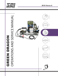
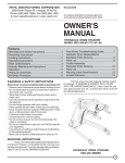
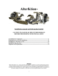
Download Green Dragon Operations and Service Manual
Transcript
GREEN DRAGON OPERATIONS & SERVICE MANUAL 2014 VERSION C GREEN DRAGON OPERATIONS AND SERVICE MANUAL - Version C Issue Date: NOVEMBER 2014 PLEASE READ BEFORE USING. SEI INDUSTRIES LTD. 7400 Wilson Avenue Delta, B.C. Canada V4G 1E5 Phone: (604) 946-3131 Fax: (604) 940-9566 E-Mail: [email protected] Website: www.sei-ind.com COPYRIGHT © 2014 SEI INDUSTRIES LTD. ALL RIGHTS RESERVED PRINTED IN CANADA Green Dragon from SEI Industries 2014 Green Dragon Operations and Service Manual (Version C) Table of Contents Section 1: Dragon System Overview 1 Dragon Eggs .................................................................................................................1 Green Dragon Dispenser ..............................................................................................2 Standard Components ....................................................................................2 Base Assembly ................................................................................................3 Hopper ............................................................................................................4 Launcher System ............................................................................................4 Launcher System (continued) .........................................................................5 Gas System ....................................................................................................6 Gas System (continued) .................................................................................7 Glycol System .................................................................................................7 Glycol System (continued).............................................................................. 8 Main Control Panel .........................................................................................8 Main Control Panel (continued) ......................................................................9 Remote Control ..............................................................................................9 Power Cord .....................................................................................................9 Principles of Operation ...............................................................................................10 Loading Operation ........................................................................................10 Hopper Operation .........................................................................................10 Launcher Operation ......................................................................................10 Modes of Operation ......................................................................................12 Section 2: Installation 13 Installation ..................................................................................................................13 Mounting Options .........................................................................................13 Gas System ..................................................................................................14 Electrical System ..........................................................................................15 Glycol System ...............................................................................................16 Dragon Eggs .................................................................................................17 Section 3: Operations 18 Green Dragon Operations ..........................................................................................18 Section 4: Emergency Procedures 21 Launcher Jams ...........................................................................................................21 Clearing a Jam .............................................................................................21 Section 5: Troubleshooting 23 Won’t Power On .........................................................................................................23 Won’t Load .................................................................................................................23 Won’t Cycle ................................................................................................................24 Green Dragon from SEI Industries 2014 Green Dragon Operations and Service Manual (Version C) Intermittent Operation .................................................................................................25 Egg Jamming ..............................................................................................................25 Loss of Range ............................................................................................................26 Ignition Failure ............................................................................................................26 Section 6: Service 28 Cleaning and Storage .................................................................................................28 Daily Cleaning Routine .................................................................................28 Weekly Cleaning Routine .............................................................................29 Storage .......................................................................................................................32 System Components and Parts Lists .........................................................................33 Base Drawing ...............................................................................................33 Base Parts List .............................................................................................34 Launcher Drawings and Parts Lists ..............................................................35 Hopper Drawings and Parts Lists ................................................................. 40 Gas Manifold Drawing and Parts List ...........................................................44 Control Panel Drawing and Parts List ...........................................................45 Simplified Electrical Schematic .....................................................................46 Simplified Pneumatic Schematic ..................................................................47 Parts Cross Reference List .........................................................................................48 Parts Cross Reference List (continued) ........................................................49 Section 7: Specifications 50 Dispenser Specifications ............................................................................................50 Dragon Egg Specifications .........................................................................................50 Safety ...........................................................................................................51 Dragon Egg Shipping Box Certifications ......................................................51 Section 8: Warranty 52 Appendix 53 Green Dragon from SEI Industries 2014 Green Dragon Operations and Service Manual (Version C) Section 1: Dragon System Overview Dragon Eggs Section 1: Dragon System Overview The use of controlled, prescribed or back burning techniques provide an effective tool in the ongoing commitment to forest and wildland management. Delayed chemical ignition devices (DCIDs) have a lengthy, proven track record of providing a means of initiating these burns in an efficient, safe and controllable manner. This manual details the operation and field maintenance of the Green Dragon from SEI Industries Ltd. Dragon Eggs Dragon Eggs are small, 26 mm diameter, two colour (orange/ white), ignition eggs made of high impact polystyrene (HIPS) plastic filled with three grams of potassium permanganate. In this state, the eggs are stable provided the shells remain undamaged. When injected with ethylene glycol (anti-freeze), an exothermic reaction initiates. After a delay of approximately 30 seconds, combustion commences with white smoke being expelled from the needle hole followed by sphere ignition. Once ignited, the plastic shell is consumed as fuel. The total combustion time, following ignition, is about 80 seconds. The Green Dragon injects a constant volume of glycol into each Dragon Egg regardless of the launch rate set by the operator. As such, the auto-ignite delay time is influenced primarily by the temperatures of the Dragon Eggs and glycol. The indicated delay times are based on air/sphere temperatures of 50 –70 degrees F (10 – 20 degrees C). Increased temperatures will decrease the delay time. By diluting the glycol with water to a 50/50 mix, the delay time can be increased. Green Dragon from SEI Industries 2014 Green Dragon Operations and Service Manual (Version C) 1 Section 1: Dragon System Overview Green Dragon Dispenser Green Dragon Dispenser Standard Components The primary function of the Green Dragon is to inject a measured amount of ethylene glycol into Dragon Eggs, thereby initiating an exothermic reaction, and then propel the primed eggs from the launcher. The Green Dragon consists of eight major components. COMPONENT DESCRIPTION Base Assembly Attaches the dispenser to the operator’s platform. Stores the unprimed eggs. Provides an egg to the launcher when required. Injects egg. Projects the charged egg away from the dispenser. Provides controlled amount of gas to expel eggs. Stores the glycol. Provides a fixed quantity of glycol to the injection needle. Provides warning indications. Loads outlet tube with eggs. Controls the launching speed. Arms the trigger switch. Initiates the launching sequence. Changes the operational mode. Connects the controller to a 12VDC power source. Hopper Launcher Gas System Glycol System Main Control Panel Remote Control Power Cord Hopper. Control panel. Launcher. Base. Power cord. Remote control. Green Dragon from SEI Industries Power adapter. 2014 Green Dragon Operations and Service Manual (Version C) 2 Section 1: Dragon System Overview Green Dragon Dispenser Base Assembly Elevation handle. Slide block. Azimuth handle. Isolator. Mount angle. • Mounting angles attach to either the side or end channels of the lower frame. These angles can be adjusted to any position within the channel. • U-bolts are used to attach the mounting angles to tubular mount racks of ATV / UTV vehicles. • The U-bolts can be removed and the angles attached directly to the shipping crate or other vehicle structures. • Vibration isolators connect the lower frame to the upper frame. • The azimuth lock handle controls the angle of the baseplate, hopper and launcher which rotate through 180° of adjustment. • The elevation lock handle controls elevation of the launcher. • The slide block allows separation of the launcher from the hopper to facilitate cleaning. Green Dragon from SEI Industries 2014 Green Dragon Operations and Service Manual (Version C) 3 Section 1: Dragon System Overview Green Dragon Dispenser Hopper Selector Plate Cone Vanes Cavity Outlet Tube Bypass • Stores 450 unprimed eggs. • The central cone forces the eggs to move towards the outer edge of the hopper. • On each cycle, the selector plate picks up one egg from the hopper and allows it to drop into the cavity formed by the rotor, fixed vanes, and the hopper base. • The extractor finger strips the egg in the rotor cavity and forces it into the outlet tube. • The outlet tube connects the hopper to the launcher. • The flexible vanes push on the queue of eggs in the hopper outlet tube that are waiting to be injected. • The bypass port allows eggs to be rejected from the hopper if the outlet queue is full or the dispenser is jammed. Launcher System • The receiver block of the launcher is mounted between the upper and lower frame plates. • The upper end of the receiver is bored out to receive the reciprocating barrel. • The lower end of the receiver is closed by the breech plug. • There is a side port in the receiver to receive eggs from the hopper. Green Dragon from SEI Industries 2014 Green Dragon Operations and Service Manual (Version C) 4 Section 1: Dragon System Overview Green Dragon Dispenser Launcher System (continued) Cam. Shaft. Motor. Shuttle. Injection needle. Return springs. • The drive motor, shaft and drive cams control the motion of the injection shuttle and barrel. • The injection needle shuttle reciprocates to inject and retract the needle from the egg. • The return springs work in opposition to the cams to return the injection shuttle to its upper position. • The barrel actuator is driven by the cams and causes the barrel to extend. • The barrel spring works in opposition to the barrel actuator to cause the barrel to retract. • The limit switch is activated by the upper cam and sends a signal to the controller when the launch cycle is complete. Barrel. Spring. Actuator. Limit switch. Cam. Green Dragon from SEI Industries 2014 Green Dragon Operations and Service Manual (Version C) 5 Section 1: Dragon System Overview Green Dragon Dispenser Gas System The Green Dragon will operate with a variety of non-flammable propellant gasses including, but not limited to, CO2 and compressed air. CAUTION The propellant gas must be supplied at a pressure of 150 psi or less. The Green Dragon dispenser is supplied with a 150 psi regulator designed to attach to CO2 bottles with CGA-320 fittings. • • The primary regulator is connected to the gas system using flexible hose and standard industrial quick connects. Primary regulator. The safety valve protects the gas system from over pressure. CO2 bottle (by user). • The adjustable gas pressure regulator allows the operator to control the range of the projectile. Pushing down the outer ring locks the regulator setting. • The pressure gauge displays the regulated gas pressure. • The low-pressure switch measures the regulated gas pressure. Safety valve. Regulator. Green Dragon from SEI Industries Gauge. Pressure switch. 2014 Green Dragon Operations and Service Manual (Version C) 6 Section 1: Dragon System Overview Green Dragon Dispenser Gas System (continued) Shot Valve. Shot tank. • The shot tank stores the gas charge to be used each time the launcher is cycled. • The shot tank is connected to the breech of the launcher by a solenoid control valve. Operation of the valve is controlled at the main control panel. Glycol System • The glycol bottle stores the glycol. • A self-closing disconnect fitting is located on the bottom of the bottle. This allows the glycol supply tube to be removed from the bottle and the bottle to be removed from the dispenser for easier filling and draining. Green Dragon from SEI Industries 2014 Green Dragon Operations and Service Manual (Version C) 7 Section 1: Dragon System Overview Green Dragon Dispenser Glycol System (continued) Pump. Outlet check valve. Inlet check valve. • The glycol pump is a piston type pump operated by the action of the needle shuttle. • The inlet check valve controls the flow of glycol into the pump from the glycol bottle • The outlet check valve controls the flow of glycol out of the pump to the injection needle. Main Control Panel Low Pressure. Power. Speed. Green Dragon from SEI Industries Load Safe / Armed 2014 Green Dragon Operations and Service Manual (Version C) 8 Section 1: Dragon System Overview Green Dragon Dispenser Main Control Panel (continued) • A resetable circuit breaker is located on the end of the main control panel. • The power indicator illuminates when the dispenser is connected to external power and the circuit breaker is pushed in. • The low pressure indicator illuminates when there is insufficient gas pressure to safely operate the dispenser. • The safe / armed switch is used to prevent trigger signals from activating the dispenser. • The load switch is used to fill the hopper outlet tube with eggs. • The speed control varies the cycle speed of launcher when in automatic mode. Remote Control • The trigger switch is used to initiate an operational cycle of the dispenser. • The auto/manual switch is used to change between automatic and manual modes of operation. Trigger. Auto / Man Power Cord • The power cord connects the main control panel to the power adapter. • The standard power adapter connects the power cord to a user-supplied power source. Power cord. Green Dragon from SEI Industries Adapter. 2014 Green Dragon Operations and Service Manual (Version C) 9 Section 1: Dragon System Overview Principles of Operation Principles of Operation The Green Dragon launcher operates on the principle of a single cycle operation. Each time a cycle is initiated, both the hopper and launcher complete one cycle and stop. When the dispenser is stopped between cycles, there are no charged eggs in the dispenser. Loading Operation Before the launcher can be operated, the outlet tube connecting the hopper and the launcher must be loaded with five eggs. This can be accomplished by pressing and releasing the load switch on the main control panel. The hopper will operate independently for five cycles to load the outlet tube. During this loading process, the launcher will not respond to trigger signals. If the tube remains loaded from previous use, the load operation is not necessary. Hopper Operation At the start of the cycle, the extractor finger strips the egg from the rotor cavity and adds it to the queue of eggs in the outlet tube. Further rotation causes the flexible vanes in the hopper to apply a constant pushing pressure to the eggs in the queue. Once the rotor cavity passes by the extractor, the selector plate loads another egg from the hopper into the cavity for the next cycle. At the end of its cycle, the hopper reaches its limit switch and stops rotating. Launcher Operation On the first phase of the cycle, the injection needle shuttle is forced downwards by the drive cams. This causes the injection needle to pierce the last egg in the queue. During the final portion of the phase, the injection shuttle pushes down on the piston of the glycol pump, causing it to inject glycol into the egg through the needle. Needle extended. Pump compressed. Green Dragon from SEI Industries 2014 Green Dragon Operations and Service Manual (Version C) 10 Section 1: Dragon System Overview Principles of Operation During the second phase of the cycle, the drive cams allow the injection shuttle springs to push the injection shuttle upwards and retract the needle from the egg. The glycol pump returns to its neutral position and recharges with glycol for the next cycle. Needle retracted. Pump extended. During the third phase of the cycle, the cams push on the barrel actuator, causing the barrel to extend from the receiver. At the end of the stroke, the barrel is fully extended and the side port in the receiver is open. Pressure from the flexible vanes in the hopper pushes the charged Barrel extended. egg into the receiver. Port open. During the final phase of the cycle, the barrel spring forces the barrel to retract to its closed position, closing over the charged egg in the receiver. When the barrel is fully retracted, its lower end seals against an O-ring in the breech. When the cams reach the end of their cycle, they trigger the limit switch. The limit switch stops the drive motor and sends a signal to the controller to open the shot valve momentarily. The gas charge in the shot tank enters the breech of the barrel and propels the charged egg from the barrel. Green Dragon from SEI Industries Barrel retracted. Port closed. 2014 Green Dragon Operations and Service Manual (Version C) 11 Section 1: Dragon System Overview Principles of Operation Modes of Operation In the manual mode of operation, each time the trigger is pulled and released, the launcher will complete one cycle and stop. Holding down the trigger will cause the dispenser to continue to cycle at the fastest possible speed until the trigger is released. When released, the dispenser completes the cycle that it has started. In the automatic mode of operation, the dispenser will cycle continuously without holding down the trigger. In this mode, the trigger is used as a toggle to both start and stop operation. During automatic mode, the speed of operation can be controlled with the speed selector which controls the time delay between cycles. In either mode of operation, if the gas pressure drops below a preset limit, the launcher will complete its current cycle and then stop. It will not initiate a new cycle until the gas pressure has been restored. Green Dragon from SEI Industries 2014 Green Dragon Operations and Service Manual (Version C) 12 Section 2: Installation Installation Section 2: Installation Installation Mounting Options The launcher is designed to mount to a variety of vehicle platforms. The most important factor to consider when mounting the launcher is the arc of fire. The launcher has a 180° arc of fire that must face away from the operator. Typical mounting arrangements are as follows: • Truck – mounted to the top of the shipping crate facing to the rear. • ATV – mounted to the rear utility rack facing to the rear. • UTV – mounted to the front utility rack facing forwards. Green Dragon from SEI Industries 2014 Green Dragon Operations and Service Manual (Version C) 13 Section 2: Installation Installation Gas System If CO2 gas bottle is used as a propellant, the bottle must be mounted in a vertical position to prevent liquid entering the launcher and causing damage. Mounting brackets are provided to attach a standard 20lb beverage style bottle to the side of the shipping crate. 1. Attach the primary regulator to the gas bottle. 2. Attach the flexible hose to the primary regulator. 3. Connect the flexible hose to the fitting on the manifold. CAUTION Carbon Dioxide (CO2) bottles must be used in a vertical position. Failure to do so may cause permanent damage to the launcher. If using compressed air as a propellant, there are no mounting position restrictions. Green Dragon from SEI Industries 2014 Green Dragon Operations and Service Manual (Version C) 14 Section 2: Installation Installation Electrical System The Green Dragon operates on a 12VDC system. 1. Attach the power cord to the receptacle on the control enclosure. 2. Attach the power adapter to the power cord. 3. Attach the power adapter to a 12VDC power supply. 4. Attach the remote control to the receptacle on the control panel. Power cord attached to control enclosure. Remote control connected. Green Dragon from SEI Industries 2014 Green Dragon Operations and Service Manual (Version C) 15 Section 2: Installation Installation Glycol System Important Note Use only 100 per cent ethylene glycol to ensure proper ignition. Do not use 50/50 pre-mix or propylene glycol. The glycol system uses undiluted ethylene glycol (anti-freeze). To fill and prime the system: 1. Disconnect the glycol supply tube from the glycol bottle by pushing up on the blue ring of the disconnect fitting while pulling down on the tubing. 2. Remove the bottle from the dispenser and fill with ethylene glycol. Replace the bottle and tubing. If the launcher has been allowed to run completely out of glycol, it may require priming of the glycol pump. To check the pump priming: 1. Squeeze down on the glycol pump piston. 2. Glycol should squirt out of the injection needle. 3. If it does not, the system requires priming. Green Dragon from SEI Industries 2014 Green Dragon Operations and Service Manual (Version C) 16 Section 2: Installation Installation To prime the glycol system: 1. Remove the glycol supply tubing from the pump inlet check valve and allow the supply tube to fill with glycol. 2. Once the supply tube has filled with glycol, replace the tube into the inlet valve. 3. Squeeze and release the pump piston repeatedly until glycol flows from the injection needle. 4. Wipe up any glycol spills. Dragon Eggs Observe safe handling practices for the Dragon Eggs. See Section 8 for the MSDS information. 1. Fill the hopper with Dragon Eggs. Green Dragon from SEI Industries 2014 Green Dragon Operations and Service Manual (Version C) 17 Section 3: Operations Green Dragon Operations Section 3: Operations Green Dragon Operations To operate the Green Dragon: 1. Press in the circuit breaker. • • 2. The POWER indicator will illuminate. The LOW PRESSURE indicator will illuminate. Open the valve on the gas bottle or air system, as applicable. • The LOW PRESSURE indicator should extinguish. 3. If the outlet tube is empty, press and release the load switch. 4. Adjust the azimuth of the launcher. Green Dragon from SEI Industries 2014 Green Dragon Operations and Service Manual (Version C) 18 Section 3: Operations Green Dragon Operations 5. Adjust the elevation of the launcher. 6. Select the operational mode using the switch on the remote control. MAN AUTO pull and release the trigger to shoot single eggs. pull and hold the trigger to shoot continuously. pull and release the trigger to start shooting. pull and release the trigger to stop shooting. 7. If in AUTO mode, select the launch speed to get the desired ground spacing. 8. Adjust the pressure regulator to give the desired range. Pull up on the locking ring of the pressure regulator before attempting to rotate. Green Dragon from SEI Industries 2014 Green Dragon Operations and Service Manual (Version C) 19 Section 3: Operations 9. Green Dragon Operations Set the safety switch to the ARMED position. 10. Pull the trigger to initiate operation. CAUTION The projectiles from the launcher are moving at a high speed and can cause personal injury. CAUTION Whenever leaving the dispenser unattended, ensure the safety switch is in the SAFE position. 11. Add more eggs as required. CAUTION Do not allow the hopper to run out of eggs. If this occurs, the vanes cannot push the primed egg into the launcher and a fire will result. Green Dragon from SEI Industries 2014 Green Dragon Operations and Service Manual (Version C) 20 Section 4: Emergency Procedures Launcher Jams Section 4: Emergency Procedures Launcher Jams Important Note If a jam occurs in the launcher feed mechanism, it can lead to a fire in the dispenser. If this occurs, extinguish the fire using the supplied water bottle. Clearing a Jam To facilitate cleaning or clearing a jam, the launcher can be separated from the hopper. The process is as follows: 1. Set the ARMED / SAFE switch to the SAFE position. 2. Turn the slide block knob counter clockwise. Green Dragon from SEI Industries 2014 Green Dragon Operations and Service Manual (Version C) 21 Section 4: Emergency Procedures Launcher Jams 3. Slide the launcher and slide angle away from the hopper. 4. Remove the hopper outlet tube. 5. Clean as required. 6. On reassembly, note that there is a slot in the hopper outlet tube which ensures proper alignment with the hopper. Green Dragon from SEI Industries 2014 Green Dragon Operations and Service Manual (Version C) 22 Section 5: Troubleshooting Won’t Power On Section 5: Troubleshooting These remedial actions are limited to those which can be performed in the field by an operator with limited tools. Won’t Power On Dispenser will not power on and the “POWER” indicator is not illuminated. Circuit Breaker • Check that the circuit breaker is pushed in. Faulty Electrical Connection • Check that the power supply is properly connected to the power adapter. • Check that the power adapter is properly connected to the power cord. • Check that the power cord is properly connected to the receptacle on the control panel. Power Supply • Check that the power supply is 12VDC. • Check that the power adapter has been attached with the correct polarity. • • White – Positive Black – Ground Won’t Load Load switch is pushed but hopper does not operate. PLC Startup When the dispenser first powers on, the internal PLC takes several seconds before it can respond to any inputs. • Wait five seconds then push load switch again. Green Dragon from SEI Industries 2014 Green Dragon Operations and Service Manual (Version C) 23 Section 5: Troubleshooting Won’t Cycle Already Loaded The load operation can only be completed once each power cycle. • Check that the dispenser has not been loaded. • Pull out the circuit breaker. • Push in the circuit breaker and wait five seconds. • Press the load switch. Won’t Cycle Trigger switch is pulled but dispenser does not respond. PLC Startup When the dispenser first powers on, the internal PLC takes several seconds before it can respond to any inputs. • Wait for five seconds, then pull trigger. Load Cycle During the load cycle, the dispenser will not respond to trigger signals. • Wait for loading to complete, then pull trigger. Low Gas Pressure If the gas pressure is below 30 psi, the dispenser will not cycle and the “LOW PRESSURE” indicator will illuminate. • Adjust the regulator to increase the pressure above 30 psi. • Check gas supply. Safety On If the “SAFE / ARMED” switch is in the “SAFE” position, the dispenser will not respond to trigger signals. • Set the “SAFE / ARMED” switch to the “ARMED” position. Green Dragon from SEI Industries 2014 Green Dragon Operations and Service Manual (Version C) 24 Section 5: Troubleshooting Intermittent Operation Intermittent Operation Dispenser shuts down randomly and then restarts. Power Supply Voltage. A low power supply voltage will cause the dispenser to shut down and restart. • Check that the power supply voltage does not drop below 12VDC during operation. Faulty Electrical Connection • Check that the power supply is properly connected to the power adapter. • Check that the power adapter is properly connected to the power cord. • Check that the power cord is properly connected to the receptacle on the control panel. Egg Jamming When dispenser is cycled, eggs do not get loaded into the barrel properly. Outlet Tube Position Incorrect location of the outlet tube will change the position of the eggs in the tube and cause sphere jamming. • Check that the outlet tube is fully seated into the hopper. • Check that the outlet tube is fully seated in the counterbore in the receiver. Dirty Outlet Tube A dirty outlet tube can cause the eggs to drag in the outlet tube leading to a jam. • Remove the outlet tube and clean. Green Dragon from SEI Industries 2014 Green Dragon Operations and Service Manual (Version C) 25 Section 5: Troubleshooting Loss of Range Loss of Range When dispenser is cycled, eggs are not propelled the normal distance for that pressure setting. Breech Seal Leakage Gas leaking past the o-ring seal in the breech plug will reduce the effective range of the launcher. • Remove the four socket head cap screws which secure the breech plug to the receiver. • Remove the breech plug and valve assembly. • Check breech plug for debris and clean as required. • Check for damaged or missing o-ring and replace as required. • Check for damage to the breech end of the barrel and clean as required. Launcher Limit Switch Adjustment An improperly adjusted limit switch can cause the cycle to stop too soon and the valve will activate before the barrel is fully seated against the o-ring. • Cycle the launcher once. • Check that there is freedom of movement between the barrel actuator frame and the two barrel rollers. This indicates that the barrel is fully seated. • If required, adjust the launcher limit switch away from the cam to allow the cam to advance further before stopping. Ignition Failure Eggs are not igniting properly. Glycol Composition Using the wrong type of glycol can cause ignition failure. • Check that glycol is ethylene glycol and not propylene glycol. • Check that the glycol has not been diluted with water (automotive antifreeze is often sold as a 50/ 50 mix of glycol and water). Green Dragon from SEI Industries 2014 Green Dragon Operations and Service Manual (Version C) 26 Section 5: Troubleshooting Ignition Failure Ambient Temperature The ambient air temperature changes the effect of the reaction. • Burning, when the ambient air temperature is less than 32°F / 0°C, can cause delayed or poor ignition. Injection Needle A plugged or damaged injection needle will prevent glycol from entering the eggs. • Disconnect the glycol outlet line that connects the outlet check valve to the elbow on the needle shuttle. • Press the needle shuttle to cycle the glycol pump. • If glycol comes out of the outlet line, then the problem is with the needle. • Check the needle for blockage and clean as required. Glycol Pump System Faulty inlet or outlet check valves on the glycol pump will prevent it from pumping glycol. • Disconnect the glycol inlet line from the bottom of the glycol reservoir (the fitting on the reservoir is self-sealing and will not leak). • Press the needle shuttle to cycle the glycol pump. • If the glycol comes out of the inlet line, the inlet check valve is stuck open and needs cleaning or replacing. • Re-attach the glycol inlet line to the bottom of the glycol reservoir. • Disconnect the glycol outlet line that connects the outlet check valve to the elbow on the needle shuttle. Seal the end of the glycol outlet line with your thumb. • Press and release the needle shuttle once to cycle the glycol pump. • Remove your thumb from the glycol outlet and cycle the pump again. • If glycol comes out of the outlet line, the outlet check valve is stuck open and needs cleaning or replacing. Green Dragon from SEI Industries 2014 Green Dragon Operations and Service Manual (Version C) 27 Section 6: Service Cleaning and Storage Section 6: Service Cleaning and Storage Regular cleaning of the Green Dragon is the most important maintenance function. During each operational cycle, a small amount of potassium permanganate powder and glycol can leak out of the punctured hole in the sphere and be deposited in the launcher. Over the course of thousands of eggs, this can build up and cause feeding problems between the hopper and launcher. Daily and weekly cleaning routines need to be performed to keep the launcher operating reliably. The recommended cleaners are citrus based solvents such as Simple Green all purpose cleaner. These cleaners do not contain any oils which can cause dust and debris to accumulate in the moving parts of the launcher. All of the bearing surfaces in the launcher are made from self-lubricating materials. There is no need to lubricate them. Daily Cleaning Routine • Loosen the slide locking knob and slide the launcher to the right. • Remove the hopper outlet tube. • Spray the inside of the outlet tube with cleaner and wipe it as clean as possible. This is the most critical part in the dispenser to be kept clean. • Pull the barrel outward and spray cleaner into the side port of the receiver. Wipe out as much of the receiver and barrel as is accessible. • Wipe the needle shuttle and shuttle guides. • Inspect the injection needle to ensure that it is sharp and straight. • Wipe up any glycol which has dripped from the breech plug drain port. • Wipe out the hopper. • Replace the outlet tube. • Slide the launcher back to its correct position and lock in place. Green Dragon from SEI Industries 2014 Green Dragon Operations and Service Manual (Version C) 28 Section 6: Service Cleaning and Storage Weekly Cleaning Routine • Disconnect the air line to the shot tank. • Disconnect the glycol line to the glycol pump inlet valve. • Disconnect the electrical connection to the launcher. • Unscrew the elevation lock handle completely and remove the launcher. Green Dragon from SEI Industries 2014 Green Dragon Operations and Service Manual (Version C) 29 Section 6: Service Cleaning and Storage • Remove the four socket head cap screws which secure the front plate to the side plates of the launcher. • Remove the front plate, front bearing, barrel and barrel spring. • Wipe out the inside of the front bearing and receiver bearing with a cloth. The bearings are self-lubricating and should not be oiled. • Spray the inside of the barrel with cleaner and swab out using a cloth. • Remove the four socket head cap screws which secure the breech plug to the receiver. Green Dragon from SEI Industries 2014 Green Dragon Operations and Service Manual (Version C) 30 Section 6: Service Cleaning and Storage • Remove the breech plug and valve assembly and set aside being careful not to damage the valve wires. • Remove the o-ring and clean the breech plug paying particular attention to the o-ring groove. • Clean the o-ring and examine it for signs of damage. It should be soft and pliable. Replace if necessary. • Spray the bore of the receiver with cleaner and swab it out with a cloth. • Clean the port in the side of the receiver where the hopper outlet tube mates. Green Dragon from SEI Industries 2014 Green Dragon Operations and Service Manual (Version C) 31 Section 6: Service Storage • Wipe the running surfaces of all the nylon bushings on the needle shuttle, barrel actuator and barrel. • Replace the breech plug and valve assembly into the receiver ensuring the correct orientation. Secure using the four socket head cap screws. • Install the barrel into the receiver bearing ensuring that the end with the flats is inside of the receiver. • Install the barrel spring onto the barrel. • Install the front bearing and front plate into the side plates, ensuring that the flange on the bearing is contacting the barrel spring. Secure using the four socket head cap screws. • Check the barrel alignment by pulling out the barrel and releasing. If necessary, loosen the cap screws and adjust the front plate to get the optimum alignment. • Check for damaged vanes in the hopper. Storage Proper packing of the Green Dragon will ensure that no damage occurs to the dispenser during shipping or long term storage. • Ensure that the dispenser is clean and dry. • Remove the remote control and place in the hopper. • Remove the power cord and place in the tool bag. • Remove the gas hose and place in the tool bag. • Remove the tank regulator and place in the tool bag. • Adjust the elevation of the launcher to its highest angle. • Rotate the hopper and launcher assembly to the position shown. • Place the dispenser in the crate as shown. • Close the end of the crate. • Place the tank hoops in the outer pocket. • Place the manual in the inner pocket. • Place the tool bag on the shelf. • Close the lid and latch the crate. • Store the crate in a dry location. Green Dragon from SEI Industries 2014 Green Dragon Operations and Service Manual (Version C) 32 Section 6: Service System Components and Parts Lists System Components and Parts Lists Base Drawing Green Dragon from SEI Industries 2014 Green Dragon Operations and Service Manual (Version C) 33 Section 6: Service System Components and Parts Lists Base Parts List ITEM PART NUMBER 1 2 3 DE14101 DE14102 DE14103 BASE FRAME, LOWER BASE FRAME, UPPER VIBRATION ISOLATOR 1 1 6 4 5 6 7 8 9 DE14104 DE14110 DE14111 DE14112 DE14113 DE14114 MOUNT ANGLE, BASE BASE PLATE SLIDE BLOCK SLIDE ANGLE PIVOT BLOCK PIVOT PIN 4 1 1 1 1 1 10 11 128 135 136 137 DE14115 DE14116 005085 005084 005081 005082 PIVOT NUT HANDLE, AZIMUTH SPRING, COMP, 0.625 x 0.054 x 2.75 GRIP, 1/4 x 1 x 4, RBR, BLK HANDLE, ADJ, MALE, 1/2-13 x 1-3/16 KNOB, MALE, 1/4-20 x 1-3/4 1 1 6 1 1 1 138 209 210 211 222 225 005083 000428 000513 000514 000391 000526 KEY, MACHINE, C1018, SQ, 1/8 x 3/4 SCREW, 1/4-20 x 3/4, SC, SS SCREW, 10-24 x 3/8, BC, SS SCREW, 1/4-20 x 1/2, BC, SS BOLT, 3/8-16 x 1, HX, SS U-BOLT, 1/4-20 x 1, PL 1 12 2 2 4 4 226 230 231 232 233 235 005087 001647 001648 001674 001677 001842 NUT, JAM, 3/4-16, HX, SS NUT, FLNG, NYL, 1/4-20, PL NUT, CHNL, 3/8-16, PL NUT, WING, 1/4-20, SS INSERT, THREAD, 1/4-20 x 3/8-24 WASHER, FLAT, 0.51 x 0.88 x 0.06, SS 1 12 8 8 1 1 236 237 238 239 005086 001847 001853 001819 WASHER, FLAT, 0.56 x 1.25 x 0.06, PVC WASHER, FLAT, 0.56 x 1.38 x 0.11, SS WASHER, LOCK, 3/8, SS WASHER, FLAT, 0.28 x 0.63 x 0.06, SS 1 2 4 1 Green Dragon from SEI Industries DESCRIPTION QTY 2014 Green Dragon Operations and Service Manual (Version C) 34 Section 6: Service System Components and Parts Lists Launcher Drawings and Parts Lists ITEM PART NUMBER 28 33 102 DE14250 DE14280 DE14281 106 109 110 111 112 113 125 153 206 DESCRIPTION QTY BREECH PLUG SHOT VALVE SHOT TANK 1 1 1 003646 003632 003636 003637 005106 003651 ELBOW, STR90, 3/8NPT, BR BUSHING, 3/8MNPT x 1/4FNPT, BR NIPPLE, 1/4NPT x CLS, BR NIPPLE, 3/8NPT x 2, BR PLUG, 3/8 MNPT, HXHD, BR ADAPTER, 1/8NPT x 8MM 2 1 1 1 1 1 005113 001190 000418 O-RING, BUNA N, #119 RECEPTACLE, FH, 6 PIN SCREW, 8-32 x 3/8, SC, SS 1 1 4 Green Dragon from SEI Industries 2014 Green Dragon Operations and Service Manual (Version C) 35 Section 6: Service System Components and Parts Lists Launcher Drawings and Parts Lists (continued) ITEM PART NUMBER 15 24 25 DE14204 DE14240 DE14241 FRONT PLATE BARREL BARREL ACTUATOR 1 1 1 26 27 129 132 133 206 DE14242 DE14243 005111 005108 005104 000418 BEARING, FRONT BEARING, RECEIVER SPRING, COMP, 1.500 x 0.091 x 2.63 BUSHING, FL, BRZ, 1/4 x 3/8 x 3/8 BUSHING, ST, NY, 1/4 x 1/2 x 11/16 SCREW, 8-32 x 3/8, SC, SS 1 1 1 2 4 4 210 223 224 234 000513 003685 000557 001843 SCREW, 10-24 x 3/8, BC, SS BOLT, 1/4 x 7/16 x 10-32, SH, HX, SS BOLT, 1/4 x 3/4 x 10-32, SH, HX, SS WASHER, FLAT, 0.20 x 0.50 x 0.06, SS 1 2 4 3 Green Dragon from SEI Industries DESCRIPTION QTY 2014 Green Dragon Operations and Service Manual (Version C) 36 Section 6: Service System Components and Parts Lists Launcher Drawings and Parts Lists (continued) ITEM PART NUMBER 17 18 19 DE14220 DE14221 DE14222 MOTOR MOUNT MOTOR, LAUNCHER DRIVE SHAFT 20 32 121 127 130 131 DE14223 DE14270 004217 005110 006072 005109 CAM LIMIT SWITCH, LAUNCHER TUBE, PUN, 4MM x 0.75MM, RED SPRING, COMP, 0.420 x 0.051 x 2.25 SPRING, EXT, 0.188 x 0.015 x 20.0 BUSHING, FL, BRZ, 1/2 x 5/8 x 1/4 2 1 8 IN 2 7 IN 2 138 200 204 206 209 214 005083 000364 000405 000418 000428 000538 KEY, MACHINE, C1018, SQ, 1/8 x 3/4 SETSCREW, 8-32 x 1/4, CUP, SS SCREW, 4-40 x 5/8, SC, SS SCREW, 8-32 x 3/8, SC, SS SCREW, 1/4-20 x 3/4, SC, SS SCREW, 10-32 x 1/2, MS, FHPH, SS 2 2 2 4 2 2 240 000363 SETSCREW, 8-32 x 1/8, CUP, SS 1 Green Dragon from SEI Industries DESCRIPTION QTY 1 1 1 2014 Green Dragon Operations and Service Manual (Version C) 37 Section 6: Service System Components and Parts Lists Launcher Drawings and Parts Lists (continued) ITEM PART NUMBER DESCRIPTION QTY 30 31 119 DE14261 DE13223 004228 PUMP MANIFOLD GLYCOL PUMP VALVE, NON-RETURN, 1/8MNPT -> 4MM 1 1 1 120 124 004230 005112 VALVE, NON-RETURN, 6MM -> 1/8MNPT O-RING, BUNA N, #007 1 1 Green Dragon from SEI Industries 2014 Green Dragon Operations and Service Manual (Version C) 38 Section 6: Service System Components and Parts Lists Launcher Drawings and Parts Lists (continued) ITEM PART NUMBER 12 13 14 DE14201 DE14202 DE14203 RECEIVER UPPER FRAME LOWER FRAME 1 1 1 16 21 22 23 116 133 DE14210 DE14230 DE14231 DE14232 003643 005104 TRUNNION BLOCK NEEDLE SHUTTLE SHUTTLE GUIDE NEEDLE ASSEMBLY ELBOW, STR90, 1/8NPT x 4MM BUSHING, ST, NY, 1/4 x 1/2 x 11/16 1 1 2 1 1 2 201 203 206 215 224 000525 005238 000418 000444 000557 SETSCREW, 10-32 x 1/4, CUP, SS SCREW, 8-32 x 1/4, LSC, SS SCREW, 8-32 x 3/8, SC, SS SCREW, 8-32 x 3/8, FSC, SS BOLT, 1/4 x 3/4 x 10-32, SH, HX, SS 1 1 12 4 2 Green Dragon from SEI Industries DESCRIPTION QTY 2014 Green Dragon Operations and Service Manual (Version C) 39 Section 6: Service System Components and Parts Lists Hopper Drawings and Parts Lists ITEM PART NUMBER DESCRIPTION QTY 42 DE14510 HOPPER BASE 1 53 DE14540 HOPPER TUBE 1 54 DE14541 OUTLET TUBE 2 Green Dragon from SEI Industries 2014 Green Dragon Operations and Service Manual (Version C) 40 Section 6: Service System Components and Parts Lists Hopper Drawings and Parts Lists (continued) ITEM PART NUMBER DESCRIPTION 48 DE14530 ROTOR 1 49 DE14531 VANE, FLEXIBLE 12 50 DE14532 VANE, RIGID 2 51 DE14533 SELECTOR PLATE 1 52 DE14334 CONICAL DEFLECTOR 1 56 DE13526 LOCATE PIN 2 202 005151 SCREW, 1/4-20 x 3/8, SET, CUP, SS 12 208 000552 SCREW, 10-24 x 2-1/4, SC, SS 1 210 000513 SCREW, 10-24 x 3/8, BC, SS 1 239 001735 PIN, SPLIT, 1/8 x 1/4, SS 1 Green Dragon from SEI Industries QTY 2014 Green Dragon Operations and Service Manual (Version C) 41 Section 6: Service System Components and Parts Lists Hopper Drawings and Parts Lists (continued) Green Dragon from SEI Industries 2014 Green Dragon Operations and Service Manual (Version C) 42 Section 6: Service System Components and Parts Lists Hopper Drawings and Parts Lists (continued) ITEM PART NUMBER DESCRIPTION QTY 42 DE14510 HOPPER BASE 1 43 DE14520 MOTOR PLATE 1 44 DE14521 HOPPER MOTOR 1 45 DE14522 MICROSWITCH BLOCK 1 46 DE14523 HOPPER LIMIT SWITCH 1 47 DE14524 MOTOR COUPLING 1 55 DE14542 EXTRACTOR 1 63 DE14302 HOPPER ADAPTER 1 117 003649 ELBOW , STR90, 1/8NPT x 8MM 2 134 005138 BUSHING, ST, NY, 1/4 x 5/8 x 1/16 1 205 000414 SCREW , 6-32 x 7/8, SC, SS 4 213 000448 SCREW , 10-24 x 1/2, FHPH, SS 4 214 000538 SCREW , 10-32 x 1/2, FHPH, SS 2 217 000477 SCREW , 4-40 x 1, PNPH, SS 2 218 000481 SCREW , 6-32 x 1/4, PNPH, SS 1 227 001657 NUT, HX, NYL, 4-40, SS 2 Green Dragon from SEI Industries 2014 Green Dragon Operations and Service Manual (Version C) 43 Section 6: Service System Components and Parts Lists Gas Manifold Drawing and Parts List ITEM PART NUMBER 34 101 103 DE14301 005131 005133 104 105 107 108 110 115 117 123 140 DESCRIPTION QTY GAS MANIFOLD REGULATOR, GAS, 2-125PSI, 1/4 NPT VALVE, RELIEF, 25-200PSI, 1/4NPT 1 1 1 005132 003639 003640 003631 003636 003642 GAUGE, PRES, 0-160PSI, 1/8 NPT ADAPTER, QUICK x 1/4MNPT TEE, STR, 1/4MNPT x 1/4FNPT BUSHING, 1/4MNPT x 1/8FNPT, BR NIPPLE, 1/4NPT x CLS, BR ELBOW, 8MM 1 1 1 2 2 1 003649 004220 001310 ELBOW, STR90, 1/8NPT x 8MM TUBE, PUN, 8MM x 1.25MM, BLU PRES SWITCH, SPDT, 0-30PSI, 1/4 NPT Green Dragon from SEI Industries 1 1 IN 1 2014 Green Dragon Operations and Service Manual (Version C) 44 Section 6: Service System Components and Parts Lists Control Panel Drawing and Parts List ITEM PART NUMBER 141 142 143 001369 005095 001355 SWITCH, TOGGLE, SPST, 15A, 125VAC SWITCH, TOGGLE, SPST, 20A, 125VAC BOOT, TOGGLE SWITCH, 15/32, GRY 1 1 1 144 145 146 147 148 149 006022 005139 005094 001368 001303 001302 BOOT, TOGGLE SWITCH, 15/32, YEL SWITCH GUARD, 1 x 1, 4-40 POTENTIOMETER, 5K OHM, 1/2 W KNOB, ABS, 0.85 DIA, 1/4 SHAFT LED, 12VDC, 700MCD, GRN LED, 12VDC, 700MCD,RED 1 2 1 1 1 1 151 000896 BREAKER, CIRCUIT, 3A 1 Green Dragon from SEI Industries DESCRIPTION QTY 2014 Green Dragon Operations and Service Manual (Version C) 45 Section 6: Service System Components and Parts Lists Simplified Electrical Schematic Green Dragon from SEI Industries 2014 Green Dragon Operations and Service Manual (Version C) 46 Section 6: Service System Components and Parts Lists Simplified Pneumatic Schematic Green Dragon from SEI Industries 2014 Green Dragon Operations and Service Manual (Version C) 47 Section 6: Service Parts Cross Reference List Parts Cross Reference List The purpose of this section is to provide a cross reference to alternate parts suppliers for the non-proprietary components used in the dispenser. The item number in the table corresponds to the item number used in the expanded drawings in this section of the manual. Item 101 103 104 105 106 107 108 109 110 111 112 113 114 115 116 117 119 120 121 122 123 124 125 126 127 128 129 130 132 133 134 135 136 137 138 140 141 142 143 144 145 Description REGULATOR, GAS, 2-125PSI, 1/4 NPT VALVE, RELIEF, 25-200PSI, 1/4NPT GAUGE, PRES, 0-160PSI, 1/8 NPT ADAPTER, QUICK x 1/4MNPT ELBOW, STR90, 3/8NPT, BR TEE, STR, 1/4MNPT x 1/4FNPT BUSHING, 1/4MNPT x 1/8FNPT, BR BUSHING, 3/8MNPT x 1/4FNPT, BR NIPPLE, 1/4NPT x CLS, BR NIPPLE, 3/8NPT x 2, BR PLUG, 3/8 MNPT, HXHD, BR ADAPTER, 1/8NPT x 8MM ADAPTER, QUICK, 1/8MNPT x 6MM ELBOW, 8MM ELBOW, STR90, 1/8NPT x 4MM ELBOW, STR90, 1/8NPT x 8MM VALVE, NON-RETURN, 1/8MNPT -> 4MM VALVE, NON-RETURN, 6MM -> 1/8MNPT TUBE, PUN, 4MM x 0.75MM, RED TUBE, PUN, 6MM x 1MM, RED TUBE, PUN, 8MM x 1.25MM, BLU O-RING, BUNA N, #007 O-RING, BUNA N, #119 VENT, 1/8MNPT,BR SPRING, COMP, 0.420 x 0.051 x 2.25 SPRING, COMP, 0.625 x 0.054 x 2.75 SPRING, COMP, 1.500 x 0.091 x 2.63 SPRING, EXT, 0.188 x 0.015 x 20.0 BUSHING, FL, BRZ, 1/4 x 3/8 x 3/8 BUSHING, ST, NY, 1/4 x 1/2 x 11/16 BUSHING, ST, NY, 1/4 x 5/8 x 1/16 GRIP, 1/4 x 1 x 4, RBR, BLK HANDLE, ADJ, MALE, 1/2-13 x 1-3/16 KNOB, MALE, 1/4-20 x 1-3/4 KEY, MACHINE, C1018, SQ, 1/8 x 3/4 PRES SWITCH, SPDT, 0-30PSI, 1/4 NPT SWITCH, TOGGLE, SPST, 15A, 125VAC SWITCH, TOGGLE, SPST, 20A, 125VAC BOOT, TOGGLE SWITCH, 15/32, GRY BOOT, TOGGLE SWITCH, 15/32, YEL SWITCH GUARD, 1 x 1, 4-40 Green Dragon from SEI Industries Supplier McMaster Carr McMaster Carr McMaster Carr Greenline Greenline Greenline Greenline Greenline Greenline Greenline Greenline Festo Festo Festo Festo Festo Festo Festo Festo Festo Festo McMaster-Carr McMaster-Carr McMaster-Carr Century Spring McMaster-Carr Century Spring McMaster Carr McMaster-Carr McMaster-Carr McMaster-Carr McMaster-Carr McMaster-Carr McMaster-Carr McMaster-Carr Newark Newark Digikey Newark Newark McMaster Carr Part Number 41735K11 50265K23 9780T11 CP21B G1698B-06-06 G16T88B-04-04 G0816B-04-02 G0816B-06-04 G1616BC-04 G1616B-06X2 G1600B-06 153004 153420 153072 153334 153048 153446 153449 178410 178411 159666 2418T113 2418T144 9833K21 71395 9657K127 S-1263 9665K53 6338K412 94638A251 96371A202 9692K15 6271K46 6085K310 98870A100 42M0461 04M4765 480-3068-ND 30F000 95B1098 1568A41 2014 Green Dragon Operations and Service Manual (Version C) 48 Section 6: Service Parts Cross Reference List Parts Cross Reference List (continued) 146 147 148 149 150 151 152 200 201 202 203 204 205 206 207 208 209 210 211 212 213 214 215 216 217 218 219 220 221 222 223 224 225 226 227 228 229 230 231 232 233 234 235 236 237 238 POTENTIOMETER, 5K OHM, 1/2 W KNOB, ABS, 0.85 DIA, 1/4 SHAFT LED, 12VDC, 700MCD, GRN LED, 12VDC, 700MCD,RED RELAY, SPDT, 12VDC, 40A BREAKER, CIRCUIT, 3A FUSE, 1/4 x 1-1/4, 0.8A, 250V SETSCREW, 8-32 x 1/4, CUP, SS SETSCREW, 10-32 x 1/4, CUP, SS SCREW, 1/4-20 x 3/8, SET, CUP, SS SCREW, 8-32 x 1/4, LSC, SS SCREW, 4-40 x 5/8, SC, SS SCREW, 6-32 x 7/8, SC, SS SCREW, 8-32 x 3/8, SC, SS SCREW, 8-32 x 1/2, SC, SS SCREW, 10-24 x 2-1/4, SC, SS SCREW, 1/4-20 x 3/4, SC, SS SCREW, 10-24 x 3/8, BC, SS SCREW, 1/4-20 x 1/2, BC, SS SCREW, 10-24 x 1/4, MS, FHPH, SS SCREW, 10-24 x 1/2, MS, FHPH, SS SCREW, 10-32 x 1/2, MS, FHPH, SS SCREW, 8-32 x 3/8, FSC, SS SCREW, 4-40 X 3/8, MS, PNPH, SS SCREW, 4-40 x 1, MS, PNPH, SS SCREW, 6-32 x 1/4, MS, PNPH, SS SCREW, 8-32 X 3/8, MS, PNPH, SS SCREW, 10-24 X 3/8, MS, PNPH, SS SCREW, 10-24 x 3/4, MS, PNPH, SS BOLT, 3/8-16 x 1, HX, SS BOLT, 1/4 x 7/16 x 10-32, SH, HX, SS BOLT, 1/4 x 3/4 x 10-32, SH, HX, SS U-BOLT, 1/4-20 x 1, PL NUT, JAM, 3/4-16, HX, SS NUT, NYL, 4-40, HX, SS NUT, NYL, 8-32, HX, SS NUT, JAM, NYL, 10-24, HX, SS NUT, FLNG, NYL, 1/4-20, PL NUT, CHNL, 3/8-16, PL NUT, WING, 1/4-20, SS INSERT, THREAD, 1/4-20 x 3/8-24 WASHER, FLAT, 0.20 x 0.50 x 0.06, SS WASHER, FLAT, 0.51 x 0.88 x 0.06, SS WASHER, FLAT, 0.56 x 1.25 x 0.06, PVC WASHER, FLAT, 0.56 x 1.38 x 0.11, SS WASHER, LOCK, 3/8, SS Green Dragon from SEI Industries Digikey Newark Newark Newark Newark Flame Newark Fastenal Fastenal Fastenal Fastenal Fastenal Fastenal Fastenal Fastenal Fastenal Fastenal Fastenal Fastenal Fastenal Fastenal Fastenal Fastenal Fastenal Fastenal Fastenal Fastenal Fastenal Fastenal Fastenal McMaster Carr McMaster Carr Fastenal Fastenal Fastenal Fastenal Fastenal Fastenal McMaster-Carr Fastenal McMaster-Carr Fastenal McMaster-Carr McMaster-Carr Fastenal Fastenal CT3012-ND 91F2244 93K6718 93K6719 30M9185 2TC2-3 48K9415 73225 73245 73258 171396 73405 73417 73421 73422 73433 73480 73742 73767 72660 72662 72682 73851 72482 72494 72383 72396 72438 72442 77105 93996A845 94035A540 42004 70837 70854 70856 129154 37337 3259T32 70910 94165A435 71010 98017A210 95611A033 71022 71067 2014 Green Dragon Operations and Service Manual (Version C) 49 Section 7: Specifications Dispenser Specifications Section 7: Specifications Dispenser Specifications Min. launch rate 12 eggs per min. Max. launch rate 40 eggs per min. Range 75 yds. Hopper capacity 450 eggs Power Supply 12 VDC Operational weight 49.0 lbs Glycol Volume 0.26 US gal 1.0 liter 70 m 22 kg Dragon Egg Specifications Dragon Egg Weight .17 oz 4.8 g Box of 1,000 Dragon Eggs 12.1 lbs 5.5 kg Injection to the first combustion (smoke) 25 seconds @ 55o F (13o C) Injection to full combustion (flame) 35 seconds @ 55o F (13o C) Total useful combustion time 80 seconds @ 55o F (13o C) Important Note Increasing ambient temperatures will decrease the ignition delay time. Green Dragon from SEI Industries 2014 Green Dragon Operations and Service Manual (Version C) 50 Section 7: Specifications Dragon Egg Specifications Safety Although stable, prior to priming with ethylene glycol, the material within the sealed Dragon Egg is classified as a hazardous substance and, as such, must be handled and transported in the correct manner. Potassium permanganate (KMnO4) is a strong oxidizer and will react violently with certain chemicals as indicated below. In addition, potassium permanganate should not be inhaled or otherwise absorbed or come in contact with the skin. WARNING There are dangerous compounds that must be isolated from the potassium permanganate in Dragon Eggs during shipping and storage. These compounds include: Antimony Aluminium Carbide Arsenic Ethylene Glycol Glycerol Hydrogen Trisulphide Hydrogen Peroxide Phosphorous Sulphur Sulphuric Acid Titanium A full MSDS sheet for the chemical is included in the appendix. Dragon Egg Shipping Box Certifications • • The complete package has been tested to meet the requirements of ISTA procedure 1A. The complete package has been tested to meet the requirements of UN 4G combination packaging. Green Dragon from SEI Industries 2014 Green Dragon Operations and Service Manual (Version C) 51 Section 8: Warranty Section 8: Warranty SEI Industries Ltd. (the Company) agrees to grant a warranty for a period of two (2) years from the date of purchase of Dragon® Fire Ignition systems on the following conditions: a) The company's sole obligation under this warranty is limited to repairing or replacing, at the company's sole discretion, any product proved to be defective. b) The company's products are not guaranteed for any specific length of time or measure of service, but are warranted only to be free from defects in workmanship and material for a period of two (2) years to the original purchaser. c) To the extent allowable under applicable law, the company's liability for consequential and incidental damages is expressly disclaimed. The company's liability in all events is limited to, and shall not exceed, the purchase price paid. d) This warranty is guaranteed to the original purchaser of Dragon® Fire Ignition systems and does not extend to a subsequent purchaser or assignee. e) The company must receive notification in writing of any claims of warranty from the original purchaser which must give details of the claimed defect in the product. f) Where the original purchaser is claiming under warranty, the product must be returned to the company for inspection with all transportation and duty charges prepaid. g) The warranty does not extend to any product that has been accidentally damaged, abraded, altered, punctured, abused, misused or used for a purpose which has not been approved by the company. h) This warranty does not apply to any accessories used with the product that are not supplied by the company and any warranty on such accessories must be requested from the manufacturer or dealer of the accessories. i) In the event the original purchaser does not give notice of a warranty claim within two (2) years of the original purchase of the product, it is understood that the purchaser has waived the claim for warranty and the purchaser and/or any subsequent purchaser must accept the condition of the product as it may be, without warranty. j) Any technical information supplied by the company regarding the product is not a condition of warranty but, rather, is information provided by the company to the best of its knowledge. k) There are no implied warranties nor is there any warranty that can be assumed from any representation of any person, except the company itself. Exclusions: l) This warranty is void if the product is not installed, used and/or maintained in accordance with the operations manual supplied by SEI. m) All Dragon® Fire Ignition systems are designed and manufactured with substantial safety margins. It is the responsibility of the user to ensure that the equipment is maintained to a safe standard. Green Dragon from SEI Industries 2014 Green Dragon Operations and Service Manual (Version C) 52 Appendix Appendix Green Dragon from SEI Industries 2014 Green Dragon Operations and Service Manual (Version C) 53 CAIROX® Potassium Permanganate EC- SAFETY DATA SHEET is prepared according to the latest adaptations to (CLP) Regulations (EC) No 1272/2008 and (EC) No 1907/2006. Thisproductisdistributedby CanadaColorsandChemicalsLimited (905) 459-1232 GeneralInquiry:(416)449Ͳ7750 24HourEmergency:(416)444Ͳ2112 Material Safety Data Sheet 754506 CCC:ProductCode:______________________ POT. PERMANGANATE BP CCC:ProductName:______________________________________ MSDS # CP-103 Section 1 Page 1 of 11 GRADE Revision Date: November 2010 Supercedes: August 2010 Identification of the Substance/Preparation and of the Company/Undertaking Potassium permanganate, KMnO4 CAIROX® Potassium Permanganate CAIROX® Potassium Permanganate Permanganic acid potassium salt, Chameleon PLQHUDO&RQG\¶VFU\VWDO Permanganate of potash Potassium Permanganate is an oxidant recommended for applications that require a SUBSTANCE/PREPARATION NAME: PRODUCT NAME: TRADE NAME: SYNONYMS: USES OF SUBSTANCE: strong oxidant. COMPANY NAME (Europe): CARUS EUROPE COMPANY NAME (US): CARUS CORPORATION Section 2 C/ Secundino Roces, 3-Planta 1ª ± Oficina 14, 33428 Cayes ± Llanera, Asturias - Spain INFORMATION: + (34) 985-785-513 EMERGENCY TELEPHONE: + (34) 985-785-513 COMPANY ADDRESS: 315 Fifth Street Peru, IL 61354, USA INFORMATION: (815) 223-1500 (815) 224-6816 (FAX) www.caruscorporation.com (Web) [email protected] (Email) EMERGENCY TELEPHONE: (800) 435 ±6856 (USA) (815) 223-1500 (Other countries) (800) 424-9300 (CHEMTREC®, USA) (703) 527-3887 (CHEMTREC , Other countries) COMPANY ADDRESS: Hazards Identification GLOBAL HARMONIZED SYSTEM (GHS) OF CLASSIFICATION OF THE SUBSTANCE Oxidizing solid, Category 2 Acute toxicity, Category 4 Aquatic toxicity (acute), Category 1 Aquatic toxicity (chronic), Category 1 GHS LABEL ELEMENTS, INCLUDING PRECAUTIONARY STATEMENTS Signal Word: DANGER Label Codes: GHS03, GHS07, GHS09 Hazard Statements: H272, H302, H400, H410 H272 H302 H410 P210 P220 P260 P280 P370 + P378 P501 P273 May intensify fire, oxidizer Harmful, if swallowed Very toxic to aquatic life with long lasting effects Keep away from heat/sparks/open flames/hot surfaces. ± No smoking Keep/Store away from clothing/combustible materials. Do not breathe dust Wear protective gloves/protective clothing/eye protection/face protection In case of fire: Use water for extinction Dispose of contents/container to appropriate places Avoid release to the environment. CAIROX®Potassium Permanganate EC- SAFETY DATA SHEET according to Regulation (EC) ʋRIWKH European Parliament and of the Council, of 16 December 2008 and amending Regulation (EC) No. 1907/2007 concerning REACH Material Safety Data Sheet Page 2 of 11 MSDS # CP-103 Section 2 Revision Date: November 2010 Supercedes: August 2010 Hazards Identification (contd.) EU CLASSIFICATION HAZARD SYMBOLS: O, Xn, N 8,22, 50/53 RISK PHRASES: HUMAN AND ENVIRONMENTAL HAZARDS Contact with combustible material may cause fire. Harmful if swallowed. Very toxic to aquatic organisms may cause long-term adverse effects in the aquatic environment. This substance is hazardous in the European Union according to the latest adaptations to Regulations (EC) No 1272/2008 and (EC) No 1907/2006. OTHER HAZARDS EYE CONTACT Potassium Permanganate is damaging to eye tissue on contact. It may cause burns that result in damage to the eye. SKIN CONTACT Momentary contact of solution at room temperature may be irritating to the skin, leaving brown stains. Prolonged contact is damaging to the skin. Concentrated solutions at elevated temperature and crystals are damaging to the skin. INHALATION Acute inhalation toxicity data are not available. However, airborne concentrations of potassium permanganate in the form of dust or mist may cause damage to the respiratory tract. INGESTION Potassium Permanganate, if swallowed, may cause burns to mucous membranes of the mouth, throat, esophagus, and stomach. HAZARDOUS MATERIALS IDENTIFICATION SYSTEM (HMIS) RATINGS Health: 1 - Slight Flammability: 0 - None Reactivity: 0 - None Personnel Protective Equipment: goggles face shield, apron, respirator and proper gloves. Section 3 CAS# 7722-64-7 Composition/Information on Ingredients Component / EC# Potassium permanganate 231-760-3 Percent >97.5 Symbols Xn N O Risks 8,22, 50/53 Component Related Regulatory Information This product may be regulated, have exposure limits or other information identified as the following: Permanganates, inorganic, n.o.s., Manganese compounds, inorganic Substance Registration Number(s) This material is produced in amounts > 1 tonne/annum and is therefore subject to REACH registration. 01-2119480139-34-0000 CAIROX®Potassium Permanganate EC- SAFETY DATA SHEET according to Regulation (EC) ʋRIWKH European Parliament and of the Council, of 16 December 2008 and amending Regulation (EC) No. 1907/2007 concerning REACH Material Safety Data Sheet Page 3 of 11 MSDS # CP-103 Section 4 Revision Date: November 2010 Supercedes: August 2010 First Aid Measures EYES Immediately flush eyes with large amounts of water for at least 15 minutes holding lids apart to ensure flushing of the entire surface. Do not attempt to neutralize chemically. Seek medical attention immediately. Note to physician: Decomposition products are alkaline. Insoluble decomposition product formed is brown colored manganese dioxide. SKIN Immediately wash contaminated areas with water. Remove contaminated clothing and footwear. Wash clothing and decontaminate footwear before reuse. Seek medical attention immediately if irritation is severe or persistent. INHALATION Remove person from contaminated area to fresh air. If breathing has stopped, resuscitate and administer oxygen if readily available. Seek medical attention immediately. INGESTION Never give anything by mouth to an unconscious or convulsing person. If person is conscious, give large quantities of water. Seek medical attention immediately. NOTE TO PHYSICIANS For inhalation, consider oxygen. Avoid gastric lavage or emesis. Decomposition products are alkaline. Insoluble decomposition product formed is brown colored manganese dioxide. Section 5 Fire Fighting Measures NFPA* HAZARD SIGNS Health Hazard 1 = Materials that under emergency conditions, can cause significant irritation. Materials that on the skin could cause irritation. Flammability Hazard 0 = Materials that will not burn under typical fire conditions, including intrinsically noncombustible materials such as concrete, stone and sand. Instability Hazard 0 = Materials that in themselves are normally stable, even under fire conditions. Special Hazard OX = Oxidizer *National Fire Protection Association 704 (USA) FIRST RESPONDERS Wear protective gloves, boots, goggles, and respirator. In case of fire, wear positive pressure breathing apparatus. Approach incident with caution. FLASHPOINT None FLAMMABLE OR EXPLOSIVE LIMITS Lower: Nonflammable Upper: Nonflammable EXTINGUISHING MEDIA Use large quantities of water. Water will turn pink to purple when in contact with potassium permanganate. Dike to contain. Do not use dry chemicals, CO2, Halon® or foams, because they are not effective. SPECIAL FIREFIGHTING PROCEDURES If material is involved in fire, flood with water. Cool all affected containers with large quantities of water. Apply water from as far a distance as possible. Wear self-contained breathing apparatus and full protective clothing. CAIROX®Potassium Permanganate EC- SAFETY DATA SHEET according to Regulation (EC) ʋRIWKH European Parliament and of the Council, of 16 December 2008 and amending Regulation (EC) No. 1907/2007 concerning REACH Material Safety Data Sheet Page 4 of 11 MSDS # CP-103 Section 5 Revision Date: November 2010 Supercedes: August 2010 Fire Fighting Measures (contd.) UNUSUAL FIRE AND EXPLOSION Powerful oxidizing material. May decompose spontaneously if exposed to heat (135°C / 275°F). May be explosive in contact with certain other chemicals (Section 10). May react violently with finely divided and readily oxidizable substances. Increases burning rate of combustible material. THERMAL DECOMPOSITION PRODUCTS: Combustion: oxides of potassium, oxides of manganese. Fire may product irritating, poisonous and/or corrosive fumes. Section 6 Accidental Release Measures OCCUPATIONAL SPILL/RELEASE Avoid contact with combustible materials. Do not touch spilled material. Move containers away from spill to a safe area. Keep unnecessary people away, isolate hazard area and deny entry. PERSONAL PRECAUTIONS Ensure adequate ventilation. Avoid dust formation. Personnel should wear protective clothing suitable for the task. Remove all ignition sources and incompatible materials before attempting clean up. ENVIRONMENTAL PRECAUTIONS Do not flush into sanitary sewer system or surface water. If accidental release into the environment occurs, inform the responsible authorities. Keep the product away from drains, sewers, surface and ground water and soil. STEPS TO BE TAKEN IF MATERIAL IS RELEASED OR SPILLED Clean up spills immediately by sweeping or shoveling up the material. Do not return spilled material to the original container; transfer to a clean metal or plastic drum. To clean up potassium permanganate solutions, follow either of the following two options. Option # 1: Dilute to approximately 6% with water, and then reduce with sodium thiosulfate, a bisulfite or ferrous salt solution. The bisulfite or ferrous salt may require some dilute sulfuric acid (10% w/w) to promote reduction. Neutralize with sodium carbonate to neutral pH, if acid was used. Decant or filter and deposit sludge in approved landfill. Where permitted, the sludge may be drained into sewer with large quantities of water. Option # 2: Absorb with inert media like diatomaceous earth or inert floor dry, collect into a drum and dispose of properly. Does not use saw dust or other incompatible media. Disposal of all materials shall be in full and strict compliance with all federal, state, and local regulations pertaining to permanganates. To clean contaminated floors, flush with abundant quantities of water into sewer, if permitted by federal, state, and local regulations. If not, collect water and treat as described above. Section 7 Handling and Storage WORK/HYGIENIC PRACTICES Wash hands thoroughly with soap and water after handling potassium permanganate. Do not eat, drink or smoke when working with potassium permanganate. Wear proper protective equipment. Remove clothing if it becomes contaminated. VENTILATION REQUIREMENTS Provide sufficient mechanical and/or local exhaust to maintain exposure below the TLV/TWA. CONDITIONS FOR SAFE STORAGE Store in accordance with NFPA 430 requirements for the Storage of Class II oxidizing materials. Protect containers from physical damage. Store in a cool, dry area in closed containers. Segregate from acids, peroxides, formaldehyde, and all combustible, organic, or easily oxidizable materials including antifreeze and hydraulic fluid. CAIROX®Potassium Permanganate EC- SAFETY DATA SHEET according to Regulation (EC) ʋRIWKH European Parliament and of the Council, of 16 December 2008 and amending Regulation (EC) No. 1907/2007 concerning REACH Material Safety Data Sheet Page 5 of 11 MSDS # CP-103 Revision Date: November 2010 Supercedes: August 2010 Section 8 Exposure Controls and Personal Protection COMPONENT EXPOSURE LIMITS Potassium permanganate (7722-64-7) ACGIH: 0.2 mg/m3 TWA (as Mn) VENTILATION Provide local exhaust or process enclosure ventilation system. Ensure compliance with applicable exposure limits. PERSONAL PROTECTIVE EQUIPMENT EYES/FACE Face shield, goggles, or safety glasses with side shields should be worn. Provide eyewash in working area. GLOVES Rubber or plastic gloves should be worn. OTHER PROTECTIVE EQUIPMENT Chemically resistant clothing covering arms and legs, and rubber or plastic apron should be worn. Caution: If clothing becomes contaminated, wash off immediately. RESPIRATORY PROTECTION In cases where overexposure to dust may occur, the use of an approved NIOSH-MSHA dust respirator or an air supplied respirator is advised. Engineering or administrative controls should be implemented to control dust. Measurement Element: Manganese (Mn) 10 mg/m3 Any particulate respirator equipped with an N95, R95, or P95 filter (including N95, R95, and P95 filtering facepieces) except quarter-mask respirators. The following filters may also be used: N99, R99, P99, N100, R100 or P100. Any supplied-air respirator. 25 mg/m3 Any supplied-air respirator operated in a continuous-flow mode. Any powered, air-purifying respirator with a high-efficiency particulate filter. 50 mg/m3 Any air-purifying, full-facepiece respirator equipped with an N100, R100, or P100 filter. Any supplied-air respirator with a tight-fitting face piece that is operated in a continuous-flow mode. Any powered, air-purifying respirator with a tight-fitting face piece and a high-efficiency particulate filter. Any self-contained breathing apparatus with a full face piece. Any supplied-air respirator with a full face piece. 500 mg/m3 Any supplied-air respirator operated in a pressure-demand or other positive-pressure mode. Emergency or planned entry into unknown concentrations or IDLH conditions Any self-contained breathing apparatus that has a full face piece and is operated in a pressure-demand or other positive-pressure mode. Escape Any air-purifying, full-face piece respirator equipped with an N100, R100, or P100 filter. Any appropriate escape-type, self-contained breathing apparatus. CAIROX®Potassium Permanganate EC- SAFETY DATA SHEET according to Regulation (EC) ʋRIWKH European Parliament and of the Council, of 16 December 2008 and amending Regulation (EC) No. 1907/2007 concerning REACH Material Safety Data Sheet Page 6 of 11 MSDS # CP-103 Revision Date: November 2010 Supercedes: August 2010 Section 9 Physical and Chemical Properties (CONTD.) APPEARANCE ODOR pH OF THE SUBSTANCE BOILING POINT/BOILING RANGE FLASH POINT FLAMMABILITY (SOLID, GAS) EXPLOSIVE PROPERTIES OXIDIZING PROPERTIES VAPOR PRESSURE ƕ RELATIVE DENSITY (AT 20 C) SOLUBILITY WATER SOLUBILITY PARTITION COEFFICEINT: n-OCTONAL/WATER VISCOSITY VAPOUR DENSITY EVAPORATION RATE MELTING POINT MOLECULAR WEIGHT Dark purple solid with metallic luster Odorless Not applicable Not applicable Not applicable Not flammable Explosive in contact with sulfuric acid or peroxides, or readily oxidizable substances Strong oxidizer Not applicable 2.7 ƕ ƕ 6% (by weight) at 20 C and 20% (by weight) at 65 C Not applicable Not applicable Not applicable Starts to decompose with evolution of oxygen (O2) at temperatures above 150qC. Once initiated, the decomposition is exothermic and self sustaining. 158.034 Section 10 Stability and Reactivity STABILITY Under normal conditions, the material is stable. CONDITIONS TO AVOID Contact with incompatible materials or heat (150qC / 302ºF) could result in violent exothermic chemical reaction. MATERIALS TO AVOID Acids, peroxides, formaldehyde, anti-freeze, hydraulic fluids and all combustible organic or readily oxidizable inorganic materials including metal powders. With hydrochloric acid, chlorine gas is liberated. HAZARDOUS DECOMPOSITION PRODUCTS When involved in a fire, potassium permanganate may liberate irritating, poisonous and/or corrosive fumes. Oxides of potassium and manganese may be formed. CONDITIONS CONTRIBUTING TO HAZARDOUS POLYMERIZATION Material is not known to polymerize. Section 11 Toxicological Information EXPOSURE SYMPTOMS DESCRIPTION INHALATION The product may be absorbed into the body by inhalation. Major effects of exposure: respiratory disorder, cough. INGESTION Harmful, if swallowed. The estimated lethal human dose is 10 g. Ingestion may cause nausea, vomiting, sore throat, stomach-ache, and eventually lead to a perforation of the intestine. Liver and kidney injuries may occur. CAIROX®Potassium Permanganate EC- SAFETY DATA SHEET according to Regulation (EC) ʋRIWKH European Parliament and of the Council, of 16 December 2008 and amending Regulation (EC) No. 1907/2007 concerning REACH Material Safety Data Sheet Page 7 of 11 MSDS # CP-103 Revision Date: November 2010 Supercedes: August 2010 Section 11 Toxicological Information (contd.) SKIN CONTACT The product may be absorbed into the body through the skin. Major effects of exposure: severe irritation, damage to the skin, and brown staining of skin. EYE CONTACT Contact with eye is damaging to eye tissues. It may cause severe burns that result in damage to the eye. ACUTE TOXICITY LC 50 inhalation: No data available. LD 50 dermal: No data available. LD 50 oral rat: 780 mg/kg male (14 days); 525 mg/kg female (14 days). Harmful if swallowed. ALD: 10g. Ingestion may cause nausea, vomiting, sore throat, stomach-ache and eventually lead to a perforation of the intestine. Liver and kidney injuries may occur. CHRONIC TOXICITY No known cases of chronic poisoning due to permanganates have been reported. Prolonged exposure, usually over many years, to heavy concentrations of manganese oxides in the form of dust and fumes may lead to chronic manganese poisoning, chiefly involving the central nervous system. CARCINOGENICITY Potassium permanganate has not been classified as a carcinogen by ACGIH, NIOSH, OSHA, NTP, or IARC. MEDICAL CONDITIONS GENERALLY AGGRAVATED BY EXPOSURE Potassium permanganate will cause further irritation of tissue, open wounds, burns or mucous membranes. Section 12 Ecological Information ECO TOXICITY Very toxic to aquatic organisms. COMPONENT ANALYSIS - AQUATIC TOXICITY Potassium permanganate (7722-64-7) 96Hr LC50 96Hr LC50 96Hr LC50 96Hr LC50 96Hr LC50 96Hr LC50 96Hr LC50 96Hr LC50 96Hr LC50 96Hr LC50 96Hr LC50 Rainbow trout Bluegill sunfish Milk fish (Chanos Chanos Carassius auratus Cyprinus carpio Cyprinus carpio Lepomis macrochirus Lepomis macrochirus Lepomis macrochirus Oncorhynchus mykiss Oncorhynchus mykiss 1.8 mg/L 2.3 mg/L >1.4 mg/L 3.3-3.93 mg/L (static) 2.97-3.11 mg/L 3.16-3.77 mg/L 2.3 mg/L (flow-through) 1.8-5.6 mg/L (static) 2.7 mg/L (static) 1.08-1.38 mg/L 0.77-1.27 mg/L MOBILITY Miscible in water. PERSISTENCE AND DEGRADABILITY Permanganate has a low estimated lifetime in the environment, being readily converted by oxidizable materials to insoluble MnO2. CAIROX®Potassium Permanganate EC- SAFETY DATA SHEET according to Regulation (EC) ʋRIWKH European Parliament and of the Council, of 16 December 2008 and amending Regulation (EC) No. 1907/2007 concerning REACH Material Safety Data Sheet Page 8 of 11 MSDS # CP-103 Revision Date: November 2010 Supercedes: August 2010 Section 12 Ecological Information BIOACCULUMATIVE POTENTIAL In non-reducing and non-acidic environments, MnO2 is insoluble and has a very low bioaccumulative potential. OTHER ADVERSE EFFECTS Harmful to aquatic organisms. Section 13 Disposal Considerations WASTE DISPOSAL Offer surplus and non-recyclable product or solutions to a licensed disposal company. Disposal of all materials shall be in full and strict compliance with all federal, state, and local regulations. This material and its container must be disposed of as hazardous waste. US EPA guidelines for the classification determination are listed in 40 CFR Parts 261.3. When it becomes a waste, potassium permanganate is considered a D001 hazardous (ignitable) waste. For disposal of potassium permanganate solutions, follow procedures in Section 6 and deactivate the permanganate to insoluble manganese dioxide. Dispose of it in a permitted landfill. Contact Carus Corporation for additional recommendations. Packaging materials must be triple rinsed to remove all residues prior to re-cycling or disposal as a non-hazardous waste. RCRA P-Series: None listed. RCRA U-Series: None listed. Section 14 Transport Information USA (Land, DOT) and Canada (TDG) European Labeling in accordance Road/Rail Transport (ADR/RID) European Labeling in accordance with EC directive (Water, IMDG) European Labeling in accordance with EC directive (IACO, IATA) ID Number: UN 1490 Proper Shipping Name: Potassium permanganate Hazard Class: Oxidizer Packing Group: II Division: 5.1 Product packaging containing OEV ID Number: UN 1490 Proper Shipping Name: Potassium permanganate, RQ Hazard Class: Oxidizer Packing Group: II Division: 5.1 Additional Info.: If this product is spilled or leaked into the environment, the CERCLA (40 CFR 302.4) reportable quantity is 100 lbs, and requires National Response Center notification within United States of America. ID Number: UN 1490 ADR/RID Class: 5.1 Description of Goods: Potassium permanganate Packing Group: II Hazard Identification No.: 50 ID Number: UN 1490 Proper Shipping Name: Potassium permanganate Hazard Class: Oxidizer Packing Group: II Division: 5.1 Marine Pollutant: No ID Number: UN 1490 Potassium permanganate Proper Shipping Name: Hazard Class: Oxidizer Packing Group: II Division: 5.1 CAIROX®Potassium Permanganate EC- SAFETY DATA SHEET according to Regulation (EC) ʋRIWKH European Parliament and of the Council, of 16 December 2008 and amending Regulation (EC) No. 1907/2007 concerning REACH Material Safety Data Sheet Page 9 of 11 MSDS # CP-103 Revision Date: November 2010 Supercedes: August 2010 Section 15 Regulatory Information EUROPEAN AND INTERNATIONAL REGULATIONS GERMANY WATER CLASSIFICATION Potassium permanganate (7722-64-7) Number 1936, hazard class 3 - severe hazard to waters CLP CLASSIFICATION This product is hazardous according to the Regulation (EC) No. 1272/2008 on Classification, Labeling and Packaging of Substances and Mixtures (CLP). Oxidizing solid, Category 2 Acute toxicity, Category 4 Hazardous to the Aquatic Environment - Hazard, Category 1 Hazardous to the Aquatic Environment - Hazard, Category 1 CLP HAZARD SYMBOLS CLP HAZARD STATEMENTS H272 H302 H410 P210 P220 P260 P280 P370 + P378 P501 P273 May intensify fire, oxidizer Harmful, if swallowed Very toxic to aquatic life with long lasting effects Keep away from heat/sparks/open flames/hot surfaces. ± No smoking Keep/Store away from clothing/combustible materials. Do not breathe dust Wear protective gloves/protective clothing/eye protection/face protection In case of fire: Use water for extinction Dispose of contents/container to appropriate places Avoid release to the environment. COMPONENT ANALYSIS ± INVENTORY COMPONENT Potassium permanganate CAS# 7722-64-7 US TSCA CA DSL EU EIN AU Yes PH Yes JP Yes KR Yes CN Yes NZ Yes This product has also been classified in accordance with the hazard criteria of the Controlled Products Regulation (CPR, Canada) and the MSDS contains all of the information required by the CPR. CAIROX®Potassium Permanganate EC- SAFETY DATA SHEET according to Regulation (EC) ʋRIWKH European Parliament and of the Council, of 16 December 2008 and amending Regulation (EC) No. 1907/2007 concerning REACH Material Safety Data Sheet Page 10 of 11 MSDS # CP-103 Revision Date: November 2010 Supercedes: August 2010 Section 15 Regulatory Information (contd.) US FEDERAL REGULATIONS: FEDERAL, STATE & INTERNATIONAL REGULATIONS ± PART 1 Ingredient Potassium permanganate CAS. NO. 7722-64-7 SARA 313 List Chemical Category Yes Yes (Manganese compounds) SARA 302 RQ TPQ No No FEDERAL, STATE & INTERNATIONAL REGULATIONS ± PART 2 Ingredient Potassium permanganate CAS. NO. 7722-64-7 CERCLA Yes (RQ = 100 lbs) Ingredient Potassium permanganate CAS. NO. 7722-64-7 CWC No Ingredient Potassium permanganate CAS. NO. 7722-64-7 Acute Yes Ingredient Potassium permanganate CAS. NO. 7722-64-7 Australian Hazchem IYE RCRA D001 TSCA 12(b) No Chronic Fire Yes Yes Pressure No WHMIS C, D2B TSCA 8(d) No CDTA SARA 311/312 4545 Kg Reactivity Pure/Liquid No Pure IDL Yes Section 16 Other Information ADR/RID C CAS CFR CERCLA CHEMTREC EINECS DOT DSL/NDSL HIMS IARC IATA ICAO IDL IMDG OSHA NIOSH NTP MSHA PEL SARA TDG TSCA TLV-TWA UN WHMIS Agreement on Dangerous Goods by Road /Regulations Concerning the International Transport of Dangerous Goods by Rail Ceiling Exposure Limit Chemical Abstract Service Code of Federal Regulations Comprehensive Environmental Response, Compensation, and Liability Act Chemical Transportation Emergency Center Inventory of Existing Chemical Substances (European) Department of Transportation The Domestic Substances and the Non-Domestic Substances List (Canada) Hazardous Materials Information System International Agency for Research on Cancer International Air Transport Association International Civil Aviation Center Ingredient Disclosure List International Maritime Dangerous Goods Occupational Safety and Health Administration National Institute for Occupational Safety and Health National Toxicology Program Mine Safety and Health Administration Permissible Exposure Limit Superfund Amendments and Reauthorization Act Transport Dangerous Goods (Canada) Toxic substances control Act Threshold Limit Value-Time Weighted Average United Nations Workplace Hazardous Materials Information System CAIROX®Potassium Permanganate EC- SAFETY DATA SHEET according to Regulation (EC) ʋRIWKH European Parliament and of the Council, of 16 December 2008 and amending Regulation (EC) No. 1907/2007 concerning REACH Material Safety Data Sheet Page 11 of 11 MSDS # CP-103 Revision Date: November 2010 Supercedes: August 2010 Section 16 Other Information (contd.) The information contained herein is accurate to the best of our knowledge. However, data, safety standards and government regulations are subject to change and, therefore, holders and users should satisfy themselves that they are aware of all current data and regulations relevant to their particular use of product. CARUS CORPORATION DISCLAIMS ALL LIABILITY FOR RELIANCE ON THE COMPLETENESS OR ACCURACY OR THE INFORMATION INCLUDED HEREIN. CARUS CORPORATION MAKES NO WARRANTY, EITHER EXPRESS OR IMPLIED, INCLUDING, BUT NOT LIMITED TO, ANY WARRANTIES OF MERCHANTIABILITY OR FITNESS FOR PARTICULAR USE OR PURPOSE OF THE PRODUCT DESCRIBED HEREIN. All conditions relating to storage, handling, and use of the product are beyond the control of Carus Corporation, and shall be the sole responsibility of the holder or user of the product. This safety data sheet was reviewed according to Annex II of the regulation of the European Parliament and European Council (EC) No. 1907/2006-REACH and 1272/2008. CARUS CORPORATION, 315 5TH STREET, PERU, ILLINOIS 61354, USA CARUS EUROPE IS A DIVISION OF CARUS CORPORATION Chithambarathanu Pillai (S.O.F.) November 2010 (Carus and design) is a registered service mark of Carus Corporation. CAIROX® is a registered trademark of Carus Corporation. Copyright 1998. Responsible Care® is a registered service mark of the American Chemistry Council


