1
JFT/JFT-S SERIES
RACKLESS CONVEYOR
FLIGHT TYPE
DISHMACHINE
TECHNICAL MANUAL
FOR JACKSON MODEL(S):
JFT/JFT-S
JFT SERIES TECHNICAL MANUAL • 7610-002-77-38 REV. Q • ISSUED: 03-16-2006 • REVISED: 11-09-2015
ONE YEAR LIMITED PARTS & LABOR
MANUFACTURERS
WARRANTY
ALL NEW JACKSON DISHWASHERS ARE WARRANTED TO THE ORIGINAL PURCHASER TO BE FREE FROM DEFECTS IN MATERIAL
OR WORKMANSHIP UNDER NORMAL USE AND OPERATION FOR A PERIOD OF (1) ONE YEAR FROM DATE OF PURCHASE, BUT IN
NO EVENT TO EXCEED (18) EIGHTEEN MONTHS FROM DATE OF SHIPMENT FROM THE FACTORY.
Jackson WWS agrees under this warranty to repair or replace, at its discretion, any original part which fails under normal use due to
faulty material or workmanship during the warranty period, providing the equipment has been unaltered and has been properly installed,
maintained and operated in accordance with applicable factory instruction manual furnished with the machine and failure is reported to
WKHDXWKRUL]HGVHUYLFHDJHQF\ZLWKLQWKHZDUUDQW\SHULRG7KLVLQFOXGHVWKHXVHRIIDFWRU\VSHFL¿HGJHQXLQHUHSODFHPHQWSDUWVSXUFKDVHG
directly from a Jackson authorized parts distributor or service agency. Use of generic replacement parts may create a hazard and void
ZDUUDQW\FHUWL¿FDWLRQ
The labor to repair or replace such failed part will be paid by Jackson WWS, within the continental United States, Hawaii and Canada, during
the warranty period provided a Jackson WWS authorized service agency, or those having prior authorization from the factory, performs the
service. Any repair work by persons other than Jackson WWS authorized service agency is the sole responsibility of the customer. Labor
coverage is limited to regular hourly rates; overtime premiums and emergency service charges will not be paid by Jackson WWS.
Accessory components not installed by the factory carry a (1) one year parts warranty only. Accessory components such as table limit
switches, pressure regulators, pre-rinse units, etc. that are shipped with the unit and installed at the site are included. Labor to repair or
replace these components is not covered by Jackson WWS.
7KLVZDUUDQW\LVYRLGLIIDLOXUHLVDGLUHFWUHVXOWIURPVKLSSLQJKDQGOLQJ¿UHZDWHUDFFLGHQWPLVXVHDFWVRI*RGDWWHPSWHGUHSDLUE\DXWKRUL]HG
persons, improper installation, if serial number has been removed or altered, or if unit is used for purpose other than originally intended.
TRAVEL LIMITATIONS
Jackson WWS limits warranty travel time to (2) two hours and mileage to (100) one hundred miles. Jackson WWS will not pay for travel
time and mileage that exceeds this, or any fees such as those for air or boat travel without prior authorization.
WARRANTY REGISTRATION
To register your product go to www.jacksonwws.com or call 1-888-800-5672. Failure to register your product will void the warranty.
REPLACEMENT PARTS WARRANTY
Jackson replacement parts are warranted for a period of 90 days from date of installation or 180 days from the date of shipment from the
IDFWRU\ZKLFKHYHURFFXUV¿UVW
PRODUCT CHANGES AND UPDATES
-DFNVRQ::6UHVHUYHVWKHULJKWWRPDNHFKDQJHVLQGHVLJQDQGVSHFL¿FDWLRQRIDQ\HTXLSPHQWDVHQJLQHHULQJRUQHFHVVLW\UHTXLUHV
7+,6,67+((17,5($1'21/<:$55$17<2)-$&.621::6-$&.621¶6/,$%,/,7<21$1<&/$,02)$1<.,1',1&/8',1*
1(*/,*(1&( :,7+ 5(63(&7 72 7+( *22'6 25 6(59,&(6 &29(5(' +(5(81'(5 6+$// ,1 12 &$6( (;&((' 7+(
35,&(2)7+(*22'6256(59,&(6253$577+(5(2):+,&+*,9(65,6(727+(&/$,0
7+(5($5(12:$55$17,(6(;35(66('25,03/,(',1&/8',1*)25),71(66250(5&+$17$%,/,7<7+$7$5(1276(7
)257++(5(,1257+$7(;7(1'%(<21'7+('85$7,21+(5(2)81'(512&,5&8067$1&(6:,//-$&.621::6%(
/,$%/()25$1</26625'$0$*(',5(&725&216(48(17,$/25)257+('$0$*(6,17+(1$785(2)3(1$/7,(6
$5,6,1*2872)7+(86(25,1$%,/,7<7286($1<2),76352'8&76
ITEMS NOT COVERED
7+,6 :$55$17< '2(6 127 &29(5 &/($1,1* 25 '(/,0,1* 2) 7+( 81,7 25 $1< &20321(17 68&+ $6 %87 127
LIMITED TO, WASH ARMS, RINSE ARMS OR STRAINERS AT ANYTIME. NOR DOES IT COVER ADJUSTMENTS SUCH AS, BUT NOT
LIMITED TO, TIMER CAMS, THERMOSTATS OR DOORS, BEYOND 30 DAYS FROM THE DATE OF INSTALLATION. IN ADDITION,
7+( :$55$17< :,// 21/< &29(5 5(3/$&(0(17 :($5 ,7(06 68&+$6 &857$,16 '5$,1 %$//6 '225 *8,'(6 25
*$6.(76'85,1*7+(),567'$<6$)7(5,167$//$7,21$/62127&29(5('$5(&21',7,216&$86('%<7+(86(
2),1&255(&7121&200(5,&$/*5$'('(7(5*(176,1&255(&7:$7(57(03(5$785(2535(6685(25+$5'
WATER CONDITIONS.
i
REVISION
HISTORY
Revision
Letter
Revision
Date
Made
By
Applicable
ECNs
C
04-30-04
CBW
N/A
D
12-16-04
Details
Updated to new format; Added missing parts to steam booster assembly.
MAW
7144, 7143
7145, 7156
Added new tall door assembly parts. Added stop brackets to unloader stop
assembly. Added keys and set screws for gears. Changed number for back
strainer support. Changed drain handle number. Changed manifold, rinse
arm and plumbing assemblies to reflect new design. Added the short door
assemblies. Corrected number for switches on load end asm. Changed
drawing for belt assembly. Added unload end assembly plumbing. Updated
schematic to revsion B. Added 600V machines.
Added spacer gaskets. Replaced level control parts with swing arm sensor.
Added final rinse arm assembly for no pump final rinse units. Added service
numbers for motor assemblies. Added new screws for door guides. Added
regulator to final rinse tank. Added dish stabilizer to blower box assembly.
Changed drain connection from 3 to 2 inches. Added new final rinse tank
assembly.
Updated dimensions page.
E
03-16-06
MAW
7316, 7176
7328, 7450
7197, 7263
7289, 7270
7331, 7343
7374
58
12-18-06
CS
7889
Replace 45KW Booster heater with 27KW booster heater.
2, 3, 4
08-20-2007
MAW
N/A
Updated electrical requirements from 45 KW to 27 KW. Changed flowrate
from 3.7 to 2.3 gpm.
35, 53, 55
09-13-2007
MAW
7836
Updated peg part number from 05700-002-63-88 to 05700-003-25-80.
Added water pressure gauge to control box and parts list.
2 THRU 11
09-14-2007
MAW
N/A
Updated the specifications and added dimensions pages.
77, 75, 60,
82, 39
10-11-2007
Updated heaters to 3Y. Replaced 4810-002-83-15 solenoid with 4820-0117673, 7818, 7816, 87-39. Added Control box door brace and button guards. Added loader/
MAW
7804, 7826, 7806 unloader strainer weldment. Added sensor cover. Added slide stop lanyard
assembly.
86-90,
113-116
12-14-2007
MAW
N/A
Updated schematic and added JFT-S 200V schematic.
91-112
01-01-2008
MAW
N/A
Updated schematics to include keyed switch option.
F
08-18-2009
ARL
*
11-23-2010
RLC
QOF 386
H
03-19-2013
RLC
QOF NDB-219
090820-1316-CW Updated p/n’s for door spring assembly.
I
02-10-14
MHH
QOF 386
J
12-16-14
.$3
N/A
ii
Added CEC note to page 15
Updated manufacturer information.
Updated manufacturer warranty.
Removed “Stop” page.
&RUUHFWHG31RIFRQYH\HUEHOWUHWXUQRQSJVZHUH
correct; arrows were pointing at wrong parts)
&RUUHFWHG31DQG'HVFULSWLRQRQSJIRURI8QORDG6HFWLRQ
Expansion Assembly.
REVISION
HISTORY
Revision
Letter
Revision
Date
Made
By
Applicable
ECNs
K
02-25-15
.$3
N/A
8SGDWHG*DOORQ(OHFWULFDO5HTXLUHPHQWV
$GGHG*DOORQ(OHFWULFDO5HTXLUHPHQWV
L
03-11-15
.$3
N/A
8SGDWHG31IRULWHPRQSJ
M
3-25-15
.$3
N/A
Corrected drawing numbers on pg. 67.
N
4-15-15
.$3
N/A
Updated Schematics
3
09-14-15
.$3
N/A
Added Drain Quench Kit on pg. 105.
Q
11-09-15
JH
N/A
Corrected part numbers on pg. 45.
Details
iii
NOMENCLATURE
JFT / JFT-S
JFT - Electrically-heated rackless conveyor dishmachine
JFT-S - Steam-heated rackless conveyor dishmachine
Model:
Serial No.:
Installation Date:
Service Rep. Name:
Phone Number:
iv
Jackson WWS, Inc.
provides technical
support for all of the
dishmachines detailed in
this manual. We strongly
recommend that you refer
to this manual before
making a call to our
technical support staff.
Please have this manual
with you when you call
so that our staff can refer
you, if necessary, to the
proper page. Technical
support is not available
on holidays.
Contact technical
support toll free at
1-888-800-5672.
Technical support is
available for service
personnel only.
TABLE OF
CONTENTS
SPECIFICATIONS
3HUIRUPDQFH&DSDELOLWLHVRIWKH-)7 ..........................................................................................1
Electrical Requirements of the JFT.............................................................................................2
3HUIRUPDQFH&DSDELOLWLHVRIWKH-)76 .......................................................................................5
Electrical Requirements of the JFT-S ......................................................................................... 6
JFT Legend & Exhaust Fan Requirements.................................................................................7
JFT Left to Right Dimensions ..................................................................................................... 8
JFT Right to Left Dimensions ..................................................................................................... 9
JFT-S Legend & Exhaust Fan Requirements ...........................................................................10
JFT-S Left to Right Dimensions ................................................................................................ 11
JFT-S Right to Left Dimensions ................................................................................................ 12
INSTALLATION/OPERATIONS INSTRUCTIONS
Installing the JFT Machine ....................................................................................................... 13
Deliming Operations .................................................................................................................19
Detergent Control .....................................................................................................................20
Operating Instructions .............................................................................................................. 21
PREVENTATIVE MAINTENANCE
3UH6FUDSSLQJ6WUDLQHUV ........................................................................................................... 24
Strainers (Cont) /Daily/Weekly Maintenance ............................................................................ 25
Weekly (Cont)/Monthly ............................................................................................................. 26
Quarterly/Annual Maintenance ................................................................................................. 27
Items Not Requiring Maintenance ............................................................................................ 28
TROUBLESHOOTING SECTION
&RPPRQ3UREOHPV ...................................................................................................................29
SERVICE PROCEDURES SECTION
9DFXXP%UHDNHU5HSDLU3DUWV.LW .............................................................................................32
PARTS SECTION
Reference Diagram................................................................................................................... 35
Load End Section ..................................................................................................................... 36
Load End Assembly .................................................................................................................. 38
/RDG(QG'UDLQ3OXPELQJ$VVHPEO\ ........................................................................................ 40
Installation of Expansion Assemblies ....................................................................................... 42
Shroud Assembly ...................................................................................................................... 43
Conveyor Belt Assembly ........................................................................................................... 45
Prewash Section ..................................................................................................................... 46
3UHZDVK6HFWLRQ$VVHPEO\ ................................................................................................... 46
3UHZDVK6HFWLRQ&RQWURO%R[$VVHPEO\ ............................................................................. 47
3UHZDVK6HFWLRQ3UHZDVK$UP'UDLQ3OXPELQJ$VVHPEO\ .............................................. 49
v
TABLE OF
CONTENTS
Wash Section .......................................................................................................................... 51
Wash Section Assembly ........................................................................................................ 51
Wash Section - Control Box Assembly .................................................................................. 52
:DVK6HFWLRQ:DVK$UP'UDLQ3OXPELQJ$VVHPEO\........................................................ 53
Power Rinse Section ..............................................................................................................56
3RZHU5LQVH6HFWLRQ$VVHPEO\ ............................................................................................. 56
3RZHU5LQVH6HFWLRQ&RQWURO%R[$VVHPEO\ ....................................................................... 57
3RZHU5LQVH6HFWLRQ5LQVH$UP'UDLQ3OXPELQJ$VVHPEO\ ............................................ 58
Final Rinse & Electrical Sections .......................................................................................... 60
)LQDO5LQVH$VVHPEO\:LWKDSXPSHG¿QDOULQVH ................................................................ 60
Final Rinse Arm Assembly ..................................................................................................... 61
´9DFXXP%UHDNHU5HSDLU3DUWV.LW$LU*DS$VVHPEOLHV .................................................. 62
Electrical Section Assembly ................................................................................................... 64
Electrical Control Box Assembly ............................................................................................ 66
Motor Overloads Chart .......................................................................................................... 70
JFT Electrical Section - Booster Heater & Frame Assembly ................................................. 71
JFT-S Electrical Section - Steam Booster Assembly ............................................................. 73
Blower Dryer Section ............................................................................................................. 76
Blower Dryer Section Assembly............................................................................................. 78
JFT Blower Assembly ............................................................................................................ 79
Unload Expansion & Unload Section(s)................................................................................. 80
18” Expansion Section Assembly .......................................................................................... 82
Unload End Assembly............................................................................................................84
Unload End Miscellaneous Assemblies ................................................................................. 88
Slide Stop Assembly ..............................................................................................................90
Motor Assemblies & JFT Heaters .......................................................................................... 91
JFT-S Steam Coil Assembly ..................................................................................................93
Door Assemblies, Tall Version ............................................................................................... 94
Door Assemblies, Short Version ............................................................................................ 96
Frame Assemblies ................................................................................................................. 98
Strainers/Curtain Assemblies............................................................................................... 100
0LVFHOODQHRXV3UHZDVK:DVK3RZHU5LQVH$VVHPEOLHV ................................................102
6SDUH3DUWV.LW*2%2;&RPSRQHQWV................................................................................ 104
Drain Quench Kit .................................................................................................................105
ELECTRICAL SCHEMATICS
-)79ROW+]3KDVH ............................................................................. 106
-)79ROW+]3KDVH ................................................................................................. 110
-)73XPSHG)LQDO5LQVH9ROW+]3KDVH.......................................... 114
-)769ROW+]3KDVH .......................................................................... 118
-)769ROW+]3KDVH...............................................................................................122
-)763XPSHG)LQDO5LQVH9ROW+]3KDVH ......................................126
-)769ROW+]3KDVH ......................................................................................... 130
vi
PERFORMANCE/CAPABILITIES: JFT
Model Designation:
SPECIFICATIONS
JFT
Operating Capacity:
'LVKHVRU*ODVVHVSHU+RXU)30
'LVKHVRU*ODVVHVSHU+RXU)30
Tank Capacity (Gallons):
3UHZDVK7DQN
Wash Tank
36
Rinse Tank
36
Pump Capacity (GPM):
3UHZDVK7DQN
Wash Tank
260
Rinse Tank
230
Venting Requirements (CFM)(100% CAP.)
)30,1',5(&7
Conveyor Speed (FPM) High End
Conveyor Speed (FPM) Low End
8.6
6.4
HOT WATER SANITIZING
Water Temperatures (Fahrenheit):
3UHZDVK7HPSHUDWXUH
Minimum Wash Temperature
152
3RZHU5LQVH7HPSHUDWXUH
Final Rinse Temperature
180
Other Water Requirements:
:DWHU)ORZ3UHVVXUH36,*
205
)ORZ5DWH0LQLPXP*30
127($OZD\VUHIHUWRWKHPDFKLQHGDWDSODWHIRUVSHFL¿FHOHFWULFDODQGZDWHU
requirements. The material provided on this page is for reference only and is
subject to change without notice.
1
SPECIFICATIONS
ELECTRICAL REQUIREMENTS: JFT
NOTE: Typical Electrical Circuit is based upon (1) 125% of the full amperage load
RIWKHPDFKLQHDQGW\SLFDO¿[HGWULSFLUFXLWEUHDNHUVL]HVDVOLVWHGLQWKH1(&
2002 Edition. Local codes may require more stringent protection than what is
displayed here. Always verify with your electrical service contractor that your
circuit protection is adequate and meets all applicable national and local codes.
These numbers are provided in this manual simply for reference and may change
without notice at any given time.
All electrical ratings provided in this manual are for reference only. Always refer to the
machine data plate to get exact electrical information for this machine. All electrical
work performed on machines should be done in accordance with applicable local,
VWDWH WHUULWRULDO DQG QDWLRQDO FRGHV :RUN VKRXOG RQO\ EH SHUIRUPHG E\ TXDOL¿HG
electricians and authorized service agents.
Where applicable, heating element amperage draws have been adjusted for the
assumed input voltage. Jackson assumes incoming voltages will be either 208 or 230
volts. Some heating elements used in the machines are rated for other voltages,
such as 240 volts. Always verify the amperage draw of the machine in operation when
sizing circuit protection.
7KHHOHFWULFDOFRQ¿JXUDWLRQVRIWKH-)7VHULHVRIPDFKLQHVDUHDVIROORZV
:$6+35(:$6+380302725
+3
32:(55,16(380302725
+3
),1$/5,16(380302725 +3
'5,9(02725
+3
.:
(;+$867)$102725
BLOWER DRYER MOTOR (1)
2
2.1 KW
ELECTRICAL REQUIREMENTS: JFT
58 Gallon/Hr
SPECIFICATIONS
JFT - Electrical Requirements
CONTROLS, MOTORS, & BLOWER DRYER SECTION
VOLTS
PH
HZ
BLOWER HEATER
RATINGS
TOTAL AMPS
TYPICAL
ELECTRICAL
CIRCUIT
208
3
60
9KW
44
$03
230
3
60
9KW
38
$03
460
3
60
9KW
19
$03
600
3
60
9KW
16
$03
CONTROLS, MOTORS, (NO BLOWER DRYER SECTION)
VOLTS
PH
HZ
BLOWER HEATER
RATINGS
TOTAL AMPS
TYPICAL
ELECTRICAL
CIRCUIT
208
3
60
N/A
12
$03
230
3
60
N/A
11
$03
460
3
60
N/A
6
$03
600
3
60
N/A
5
$03
FINAL RINSE & BOOSTER HEATER SECTION
VOLTS
PH
HZ
BOOSTER HEATER
RATINGS
TOTAL AMPS
TYPICAL
ELECTRICAL
CIRCUIT
208
3
60
18 KW
48
$03
230
3
60
18 KW
42
$03
460
3
60
18 KW
21
$03
600
3
60
18 KW
18
$03
WASH TANK SECTION
VOLTS
PH
HZ
WASH HEATER
RATINGS
TOTAL AMPS
TYPICAL
ELECTRICAL
CIRCUIT
208
3
60
24 KW
67
$03
230
3
60
24 KW
56
$03
460
3
60
24 KW
31
$03
600
3
60
24 KW
26
$03
POWER RINSE TANK SECTION
VOLTS
PH
HZ
POWER RINSE TANK
HEATER RATINGS
TOTAL AMPS
TYPICAL
ELECTRICAL
CIRCUIT
208
3
60
33 KW
92
$03
230
3
60
33 KW
77
$03
460
3
60
33 KW
40
$03
600
3
60
33 KW
33
$03
3
ELECTRICAL REQUIREMENTS: JFT
SPECIFICATIONS
139 Gallon /Hr
JFT - Electrical Requirements
CONTROLS, MOTORS, & BLOWER DRYER SECTION
VOLTS
PH
HZ
BLOWER HEATER
RATINGS
TOTAL AMPS
TYPICAL
ELECTRICAL
CIRCUIT
208
3
60
9KW
44
$03
230
3
60
9KW
38
$03
460
3
60
9KW
19
$03
600
3
60
9KW
16
$03
CONTROLS, MOTORS, (NO BLOWER DRYER SECTION)
VOLTS
PH
HZ
BLOWER HEATER
RATINGS
TOTAL AMPS
TYPICAL
ELECTRICAL
CIRCUIT
208
3
60
N/A
12
$03
230
3
60
N/A
11
$03
460
3
60
N/A
6
$03
600
3
60
N/A
5
$03
FINAL RINSE & BOOSTER HEATER SECTION
VOLTS
PH
HZ
BOOSTER HEATER
RATINGS
TOTAL AMPS
TYPICAL
ELECTRICAL
CIRCUIT
208
3
60
36 KW
100
$03
230
3
60
36 KW
83
$03
460
3
60
36 KW
42
$03
600
3
60
36 KW
35
$03
WASH TANK SECTION
VOLTS
PH
HZ
WASH HEATER
RATINGS
TOTAL AMPS
TYPICAL
ELECTRICAL
CIRCUIT
208
3
60
24 KW
67
$03
230
3
60
24 KW
56
$03
460
3
60
24 KW
31
$03
600
3
60
24 KW
26
$03
POWER RINSE TANK SECTION
VOLTS
PH
HZ
POWER RINSE TANK
HEATER RATINGS
TOTAL AMPS
TYPICAL
ELECTRICAL
CIRCUIT
208
3
60
26 KW
73
$03
230
3
60
26 KW
60
$03
460
3
60
26 KW
33
$03
600
3
60
26 KW
28
$03
4
ELECTRICAL REQUIREMENTS: JFT-S
Model Designation:
SPECIFICATIONS
JFT-S
Operating Capacity:
'LVKHVRU*ODVVHVSHU+RXU)30
'LVKHVRU*ODVVHVSHU+RXU)30
Tank Capacity (Gallons):
3UHZDVK7DQN
Wash Tank
Rinse Tank
36
36
Pump Capacity (GPM):
3UHZDVK7DQN
Wash Tank
Rinse Tank
260
230
Venting Requirements (CFM)(100% CAP.)
)30,1',5(&7
Conveyor Speed (FPM) High End
Conveyor Speed (FPM) Low End
8.6
6.4
HOT WATER SANITIZING
Water Temperatures (Fahrenheit):
3UHZDVK7HPSHUDWXUH
Minimum Wash Temperature
3RZHU5LQVH7HPSHUDWXUH
Final Rinse Temperature
152
180
Other Water Requirements:
:DWHU)ORZ3UHVVXUH36,*
)ORZ5DWH0LQLPXP*30
205
STEAM BOOSTER REQUIREMENTS
6WHDP,QSXW5DWH0LQLPXP
6WHDP,QSXW5DWH0D[LPXP
Consumption @ 110°F Incoming Water Temp
Consumption WITH BLOWER DRYER
36,*
36,*
145 lbs./hr.
245 lbs./hr.
127($OZD\VUHIHUWRWKHPDFKLQHGDWDSODWHIRUVSHFL¿FHOHFWULFDODQGZDWHU
requirements. The material provided on this page is for reference only and is
subject to change without notice.
5
ELECTRICAL REQUIREMENTS: JFT-S
SPECIFICATIONS
7KHHOHFWULFDOFRQ¿JXUDWLRQVRIWKH-)76VHULHVRIPDFKLQHVDUHDVIROORZV
:$6+35(:$6+380302725
+3
32:(55,16(380302725
+3
),1$/5,16(380302725
+3
'5,9(02725
+3
(;+$867)$102725
.:
BLOWER DRYER MOTOR (1)
2.1 KW
NOTE: Typical Electrical Circuit is based upon (1) 125% of the full amperage load of the
machine and (2) typical fixed-trip circuit breaker sizes as listed in the NEC 2002 Edition.
Local codes may require more stringent protection than what is displayed here. Always verify
with your electrical service contractor that your circuit protection is adequate and meets all
applicable national and local codes. These numbers are provided in this manual simply for
reference and may change without notice at any given time.
CONTROLS, MOTORS, & BLOWER DRYER SECTION
VOLTS
PH
HZ
RINSE HEATER
RATINGS
TOTAL AMPS
TYPICAL
ELECTRICAL
CIRCUIT
208
3
60
N/A
22
$03
230
3
60
N/A
22
$03
460
3
60
N/A
11
$03
600
3
60
N/A
10
$03
CONTROLS, MOTORS, (NO BLOWER DRYER SECTION)
VOLTS
PH
HZ
RINSE HEATER
RATINGS
TOTAL AMPS
TYPICAL
ELECTRICAL
CIRCUIT
208
3
60
N/A
15
$03
230
3
60
N/A
15
$03
460
3
60
N/A
7
$03
600
3
60
N/A
6
$03
WASH/POWER RINSE SECTIONS (COMBINED)
VOLTS
PH
HZ
RINSE HEATER
RATINGS
TOTAL AMPS
TYPICAL
ELECTRICAL
CIRCUIT
208
3
60
N/A
16
$03
230
3
60
N/A
16
$03
460
3
60
N/A
8
$03
600
3
60
N/A
7
$03
6
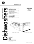
JFT EXHAUST FAN DIMENSIONS
JFT L-R & R-L
LEGEND:
SPECIFICATIONS
Legend ´1370DFKLQH'UDLQ&RQQHFWLRQ
ÀRRUGUDLQRSWLRQDOWRHLWKHUHQG
2. Wash Tank Electrical Connection
3. Rinse Tank Electrical Connection
NOTE: The condensate
removal system built into
the dishmachine consists
of a fan that will remove
1200 CFM. A single
condensate connection
must be provided by the
installing contractor. This
is an indirect connection
that must be capable of
removing the 1200 CFM
from the area.
4. Booster Heater Electrical Connection
5. Motor Controls Electrical Connection
´137,QFRPLQJ:DWHU&RQQHFWLRQ
7. Condensate Connection - See Detail
18” [457mm] I.D. Square
A.F.F.
6’-10” [2083mm]
3” [72mm] Deep
7
1’-71 ” [486mm]
8
2’-5 1 ” [743mm]
4
DIRECTION OF OPERATION
3” [76mm] Minimum
Floor Sink or Floor Drain
(Optional to drain at load or
unload end of the machine.)
6’1” [1855mm]
9’-2” [2794mm]
Doors In The Open Position
3’ [915mm]
3’ [915mm]
2’-5 3” [746mm]
8
2’-4 3 ” [721mm]
8
9 1 ” [234mm]
4
3’ [915mm]
3’ [915mm]
5 1 ” [129mm]
8
TYPICAL
Power Connections Inside Control Panel
3’ [915mm]
18’-6” [5639mm]
15’-5 1” [4712mm]
2
13’-6” [4115mm]
12’-7” [3836mm]
12’-7” [3836mm]
13’-6” [4115mm]
15’-5 1 ” [4712mm]
2
3’-6” [1067mm]
9” [229mm]
3” [76mm] Minimum
Floor Sink or Floor Drain
(Optional to drain at load or
unload end of the machine.)
1’-2 3 ” [375mm]
4
1’-71 ” [486mm]
8
6” [152mm]
3’-10” [1168mm]
7’-6” [2794mm]
Short Doors In The Open Position
2’-3 3” [706mm]
4
3’ [914mm]
10 1 ” [273mm]
2
3’-5 1 ” [1048mm]
4
3’ [914mm]
3’-2 1” [972mm]
4
3’ [914mm]
3’-21 ” [971mm]
4
8 ” [226mm]
6’-4 1 ” [1943mm]
2
Control Cabinet Door Open
5’-4 3 ” [1644mm]
4
8
6” [152mm]
SPECIFICATIONS
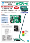
JFT LEFT - RIGHT DIMENSIONS
9’-6” [2896mm]
Maximun Ceiling Height for Short Doors - 7’-10” [2388mm]
6’-10” [2083mm]
Top of Exhaust Fan Housing
JFT RIGHT - LEFT DIMENSIONS
SPECIFICATIONS
9’-2” [2794mm]
Doors In The Open Position
3” [76mm] Minimum
Floor Sink or Floor Drain
(Optional to drain at load or
unload end of the machine.)
3’-5 1 ” [1048mm]
4
3’-21 ” [971mm]
4
2’-5 1 ” [743mm]
4
6’1” [1855mm]
3’ [914mm]
8 ” [226mm]
6” [152mm]
3’ [914mm]
3’-2 1” [972mm]
4
6’-4 1 ” [1943mm]
2
Control Cabinet Door Open
Power Connections Inside Control Panel
13’-6” [4115mm]
5 1 ” [129mm]
8
TYPICAL
18’-6” [5639mm]
6” [152mm]
10 1 ” [273mm]
2
3’ [914mm]
5’-4 3 ” [1644mm]
4
6’-10” [2083mm]
Top of Exhaust Fan Housing
9’-6” [2896mm]
Maximun Ceiling Height for Short Doors - 7’-10” [2388mm]
9
15’-5 1” [4712mm]
2
12’-7” [3836mm]
3’ [915mm]
2’-3 3” [706mm]
4
3” [76mm] Minimum
Floor Sink or Floor Drain
(Optional to drain at load or
unload end of the machine.)
9” [229mm]
1’-71 ” [486mm]
8
1’-2 3 ” [375mm]
4
3’-6” [1067mm]
3’ [915mm]
3’ [915mm]
3’ [915mm]
12’-7” [3836mm]
13’-6” [4115mm]
15’-5 1 ” [4712mm]
2
2’-5 3” [746mm]
8
2’-4 3 ” [721mm]
8
9 1 ” [234mm]
4
3’ [915mm]
1’-71 ” [486mm]
8
7’-6” [2794mm]
Short Doors In The Open Position
DIRECTION OF OPERATION
3’-10” [1168mm]
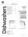
SPECIFICATIONS
JFT-S L-R & R-L
LEGEND:
JFT-S EXHAUST FAN DIMENSIONS
Legend
´1370DFKLQH'UDLQ&RQQHFWLRQ
ÀRRUGUDLQRSWLRQDOWRHLWKHUHQG
2. Electrical Connection
´137,QFRPLQJ:DWHU&RQQHFWLRQ
NOTE: The condensate
removal system built into
the dishmachine consists
of a fan that will remove
1200 CFM. A single
condensate connection
must be provided by the
installing contractor. This
is an indirect connection
that must be capable of
removing the 1200 CFM
from the area.
18” [457mm] I.D. Square
10
A.F.F.
6’-10” [2083mm]
3” [72mm] Deep
´1376WHDP&RQQHFWLRQ
´137:DVK6HFWLRQ&RQGHQVDWH5HWXUQ
´1373RZHU5LQVH6HFWLRQ&RQGHQVDWH5HWXUQ
´137%RRVWHU+HDWHU&RQGHQVDWH5HWXUQ
8. Condensate Connection - See Detail
JFT-S LEFT - RIGHT DIMENSIONS
SPECIFICATIONS
9’-2” [2794mm]
Doors In The Open Position
6’1” [1855mm]
3’ [914mm]
8 ” [226mm]
6” [152mm]
3’-10” [1168mm]
3” [76mm] Minimum
Floor Sink or Floor Drain
(Optional to drain at load or
unload end of the machine.)
DIRECTION OF OPERATION
7’-6” [2794mm]
Short Doors In The Open Position
3’-5 1 ” [1048mm]
4
3’-21 ” [971mm]
4
2’-5 1 ” [743mm]
4
1’-71 ” [486mm]
8
3’ [915mm]
3’ [915mm]
Power Connections Inside Control Panel
5 1 ” [129mm]
8
TYPICAL
3’ [915mm]
18’-6” [5639mm]
15’-5 1 ” [4712mm]
2
3’ [915mm]
13’-6” [4115mm]
12’-7” [3836mm]
2’-5 3” [746mm]
8
2’-4 3 ” [721mm]
8
9 1 ” [234mm]
4
3’ [915mm]
12’-7” [3836mm]
13’-6” [4115mm]
15’-5 1” [4712mm]
2
3’-6” [1067mm]
3’ [914mm]
5’-4 3 ” [1644mm]
4
1’-2 3 ” [375mm]
4
10 1 ” [273mm]
2
3” [76mm] Minimum
Floor Sink or Floor Drain
(Optional to drain at load or
unload end of the machine.)
6” [152mm]
9” [229mm]
1’-71 ” [486mm]
8
2’-3 3” [706mm]
4
3’ [914mm]
3’-2 1” [972mm]
4
6’-4 1 ” [1943mm]
2
Control Cabinet Door Open
6’-10” [2083mm]
Top of Exhaust Fan Housing
9’-6” [2896mm]
Maximun Ceiling Height for Short Doors - 7’-10” [2388mm]
11
JFT-S RIGHT - LEFT DIMENSIONS
SPECIFICATIONS
9’-2” [2794mm]
Doors In The Open Position
3” [76mm] Minimum
Floor Sink or Floor Drain
(Optional to drain at load or
unload end of the machine.)
3’-5 1 ” [1048mm]
4
3’-21 ” [971mm]
4
2’-5 1 ” [743mm]
4
6’1” [1855mm]
3’ [914mm]
8 ” [226mm]
6” [152mm]
3’ [914mm]
3’-2 1” [972mm]
4
6’-4 1 ” [1943mm]
2
Control Cabinet Door Open
Power Connections Inside Control Panel
5 1 ” [129mm]
8
TYPICAL
18’-6” [5639mm]
6” [152mm]
10 1 ” [273mm]
2
3’ [914mm]
5’-4 3 ” [1644mm]
4
6’-10” [2083mm]
Top of Exhaust Fan Housing
9’-6” [2896mm]
Maximun Ceiling Height for Short Doors - 7’-10” [2388mm]
12
13’-6” [4115mm]
15’-5 1” [4712mm]
2
12’-7” [3836mm]
3’ [915mm]
2’-3 3” [706mm]
4
3” [76mm] Minimum
Floor Sink or Floor Drain
(Optional to drain at load or
unload end of the machine.)
9” [229mm]
1’-71 ” [486mm]
8
1’-2 3 ” [375mm]
4
3’-6” [1067mm]
3’ [915mm]
3’ [915mm]
3’ [915mm]
12’-7” [3836mm]
13’-6” [4115mm]
15’-5 1 ” [4712mm]
2
2’-5 3” [746mm]
8
2’-4 3 ” [721mm]
8
9 1 ” [234mm]
4
3’ [915mm]
1’-71 ” [486mm]
8
7’-6” [2794mm]
Short Doors In The Open Position
DIRECTION OF OPERATION
3’-10” [1168mm]
INSTRUCTIONS
INSTALLATION
NOTE: All JFT models are accompanied by a certified
Jackson technician for the initial installation. Many of the
questions and problems that arise, as well as the proper
procedures for installation, should be directed to this
person.
VISUAL INSPECTION:
DO NOT THROW AWAY
CONTAINER IF DAMAGE
IS EVIDENT!
Before installing the unit, check the container and machine for damage. A damaged
container is an indicator that there may be some damage to the machine. If there is
damage to both the container and machine, do not throw away the container. The
dishmachine has been inspected and packed at the factory and is expected to arrive
to you in new, undamaged condition. However, rough handling by carriers or others
may result in there being damage to the unit while in transit. If such a situation occurs,
do not return the unit to Jackson; instead, contact the carrier and ask them to send
a representative to the site to inspect the damage to the unit and to complete an
inspection report.
You must contact the carrier within 48 hours of receiving the machine.
UNPACKING THE
MACHINE:
Your JFT model dishmachine will come packaged in several containers as each
individual section is packed separately. Once the machine sections have been
removed from the container, ensure that there are no missing parts from the
machine. This may not be obvious at first. If it is discovered that an item is missing,
contact Jackson immediately.
LEVEL THE
DISHMACHINE:
The dishmachine is designed to operate while being level. This is important to
prevent any damage to the machine during operation and to ensure the best results
when washing ware. The unit comes with adjustable bullet feet, which can be turned
using a pair of pliers or by hand if the unit can be raised safely. Ensure that the unit
is level from side-to-side and from front-to-back before making any connections.
Bullet Foot
13
INSTRUCTIONS
INSTALLATION
Load End
Straight
Expansion
Section
Angled
Expansion
Section
3UHZDVK
CONNECTION OF
MACHINE
COMPONETS:
Wash
3RZHU
Rinse
Control
Blower
Dryer
Straight
Expansion
Section
Angled
Expansion
Section
Unload End
The dishmachine will arrive in separate pieces for ease of installation. Silicone will
have to be used between each section for sealing purposes before each is bolted
together. Apply the sealant onto each surface to be connected together. Observe
that the openings and bolt holes are covered with the sealant. When connecting
the sections, use pins or spikes to center components before clamping the machine
together. Once clamped, the sealant will be squeezed from all cracks where applied.
The sections are now ready to have the hardware inserted into place.
DO NOT TIGHTEN THE HARDWARE AT THIS POINT!
Check that all sheet joints, bends, and—especially—guiding rails are properly aligned
and if necessary, readjust at this point. After all connections are ready, tighten the
hardware. Excess protruding sealant is to be removed with a plastic scraper. Once
removed, smooth the sealant seam with the fingers and soapy water.
PLUMBING THE
DISHMACHINE:
All plumbing connections must comply with all applicable local, state, and national
plumbing codes. The plumber is responsible for ensuring that the incoming water line
is thoroughly flushed prior to connecting it to any component of the dishmachine. It
is necessary to remove all foreign debris from the water line that may potentially get
trapped in the valves or cause an obstruction.
Any valves that are fouled as a result of foreign matter left in the water line, and any
expenses resulting from this fouling, are not the responsibility of the manufacturer.
CONNECTING THE
DRAIN LINE:
The drains for the models covered in this manual are gravity discharge drains. All
piping from the 2” connection on the load section must be pitched (1/4” per foot) to
the floor or sink drain. All piping from the machine to the drain must be a minimum 3”
137DQGPXVWQRWEHUHGXFHG7KHUHPXVW
also be an air gap between the machine
drain line and the floor sink or drain. If a
grease trap is required by code, it should
have a flow capacity of 30 gallons per
minute.
Load End Drain Connection
14
INSTRUCTIONS
WATER SUPPLY
CONNECTION:
INSTALLATION
(QVXUH WKDW \RX KDYH UHDG WKH VHFWLRQ HQWLWOHG ³3/80%,1* 7+( ',6+0$&+,1(´
above before proceeding. Install the water supply line (3/4” pipe size minimum) to the
dishmachine line strainer using copper pipe. It is recommended that a water shut-off
valve be installed in the water line between the main supply and the machine to allow
access for service.The water supply line is to be capable of 20$36,³IORZ´SUHVVXUH
at the recommended temperature indicated on the data plate.
NOTE: Units equipped with electric final rinse boosters should have the power
switch for the booster inspected to ensure it is in the ON position.
THE BOOSTER WILL NOT WORK UNLESS THIS IS ON.
)LQDO5LQVH%RRVWHU3RZHU6ZLWFK
PRESSURE
REGULATOR:
3/4” Water Supply Connection
In areas where the water pressure fluctuates or is greater than the recommended
pressure, it is suggested that a water pressure regulator be installed. The models
covered in this manual do come with water pressure regulators as standard
HTXLSPHQW 3OHDVH QRWLI\ -DFNVRQ LPPHGLDWHO\ LI WKLV FRPSRQHQW LV QRW SUHVHQW RQ
your machine.
If the water level is too low or too high, check the incoming water pressure. It should
be 20$36,7RRKLJKRISUHVVXUHUHVXOWVLQWRRPXFKZDWHUWRRORZRISUHVVXUH
results in too little water. To adjust the regulator,
loosen the nut at the top, this will allow you to screw
Adjusting
or unscrew the adjustment. With a screwdriver, turn
screw
the adjuster clockwise to increase pressure or counterLocking
clockwise to decrease it.
nut
Do not confuse static pressure with flow pressure.
Static pressure is the line pressure in a “no flow”
condition (all valves and services are closed). Flow
pressure is the pressure in the fill line when the fill valve
is opened during the cycle.
SHOCK ABSORBER:
:DWHU3UHVVXUH5HJXODWRU
It is also recommended that a shock absorber (not supplied) be installed in the
incoming water line. This prevents line hammer (hydraulic shock), induced by the
solenoid valve as it operates, from causing damage to the equipment.
15
INSTALLATION
INSTRUCTIONS
STEAM LINE
CONNECTIONS
(JFT-S ONLY):
The JFT-S is designed to use low-pressure steam as a source of heat for the water. The
machines come with lines by which the source steam
needs to be connected. The inlet steam is connected
WR WKH PDFKLQH YLD D ´ )137 <6WUDLQHU ORFDWHG
underneath the Electrical Section. The 1” steam supply
OLQHLVWREHFDSDEOHRI$36,&RQQHFWDOOVWHDP
lines to the machine as all applicable codes provide.
See machine data plate for information concerning
VWHDPÀRZSUHVVXUH
Steam Line Connection Y-strainer
STEAM TRAP
CONNECTIONS:
There are steam traps provided on the discharge side of all steam heating devices. A
typical unit will have traps on the following: wash section
heating coil outlet, power rinse section heating coil outlet,
rinse booster heater outlet, and an optional blower dryer
section heating coil outlet. All steam traps can be seen
by removing all of the above mentioned sections lower
GUHVVSDQHOV7KHVWHDPWUDSVDUH´)137DQGVKRXOG
be plumbed together to provide condensate return to the
Steam Trap
building’s boiler system.
PLUMBING CHECK:
6ORZO\WXUQRQWKHZDWHUVXSSO\WRWKHPDFKLQHDIWHUWKHLQFRPLQJ¿OOOLQHDQGWKHGUDLQOLQH
have been installed. Check for any leaks and repair as required. All leaks must be repaired
prior to placing the machine in operation.
ELECTRICAL POWER
CONNECTION:
Electrical and grounding connections must comply with
the applicable portions of the National Electrical Code
$16,1)3$ ODWHVW HGLWLRQ DQGRU RWKHU HOHFWULFDO
FRGHV HJ &DQDGLDQ (OHFWULFDO &RGH &(& 3DUW CSA). Refer to the data plate for machine operating
requirements, machine voltage, total amperage load
and serial number.To install the incoming power lines,
Control Box Electrical Connection
open the control box. Install conduit into the prepunched holes in the top of the control box. Route
power wires and connect to power block and grounding lug. Tighten the connections. It is
UHFRPPHQGHGWKDW³'(2;´RUDQRWKHUVLPLODUDQWLR[LGDWLRQDJHQWEHXVHGRQDOOSRZHU
connections.
WARNING: Disconnect
electrical power supply
and place a tag at the
disconnect switch to
indicate that you are
working on the circuit.
Terminal Block
*URXQG/XJ
3OHDVH QRWH WKDW WKH LQGLYLGXDO VHFWLRQV UHTXLUH VHSDUDWH LQFRPLQJ SRZHU VXSSOLHV DQG
services. Refer to the machine data plate for information related to service circuit sizing.
Ensure that services are labeled correctly. Ensure that service is sized correctly according
to applicable local, state, and national codes. Always refer to the machine data plate to get
the total amperage load for each section.
16
INSTRUCTIONS
VOLTAGE CHECK:
INSTALLATION
Ensure that the power switch is in the OFF position and apply power to the dishmachine.
Check the incoming power at the terminal block and ensure it corresponds to the voltage
OLVWHGRQWKHGDWDSODWH,IQRWFRQWDFWDTXDOL¿HGVHUYLFHDJHQF\WRH[DPLQHWKHSUREOHP'R
not run the dishmachine if the voltage is too high or too low. Shut off the service breaker(s)
and mark as being for the dishmachine. Advise all proper personnel of any problems and
of the location of the service breaker. Close and lock the control box cover until authorized
technicians can look at the problem and determine an appropriate solution.
The protective measures must be executed according to the conditions of the local power
utilities. All electrical cable connections are to be provided with marked cables screwed in
the electrical switch cabinet, according to the wiring diagram and to be connected to the
respective terminals and contactors.
3OHDVHFKHFNWKHHOHFWULFDOWHQVLRQ
a. Check all motors for sense of direction.
E5HWLJKWHQDOOWHUPLQDO¿[LQJVFUHZVEHIRUHWKHVHWWLQJLQRSHUDWLRQ
INSTALLATION OF
THE MACHINE’S
TRANSPORT BELT:
WARNING: Pay attention
to the cross-struts of the
machine. Be careful to not
SODFH¿QJHUVWKURXJKWKH
belt! Your hand could be
injured.
The transport belt is provided in sections of approximately 12 feet. One end of each section
ZLOOKDYHWKHEHOWURGLQVHUWHGDQGWKHRSSRVLQJHQGZLOOKDYHWKHEHOW¿QJHUVKDQJLQJGRZQ
To install the belt, stand at the load end section of the dishmachine. Remove the end cap
from one of the rods. Take the belt rod end of one
12 foot section and place on the top guide rails at
WKHORDGHQG(QVXUHWKDWWKH¿QJHUVDUHSRLQWLQJ
XSZDUG3XVKWKHVHFWLRQLQWRWKHPDFKLQHXQWLO
WKH ORRVH ¿QJHU HQG LV DSSUR[LPDWHO\ RQH IRRW
from the entrance of the machine. The next 12
foot section of the transport belt can then be
placed at the load end. Temporarily remove the
EHOWURGDQGLQWHUODFHWKH¿QJHUVRIWKHWZREHOW
Transportation Belt
sections to conform with the arrangement of all belt
¿QJHUV 3OHDVH UHIHU WR WKH GLDJUDP WR VHH WKH
order in which the provided washers, wheels,
locknuts, and plate connectors are arranged for
proper operation. Continue this process of pulling
sections through and connecting sections until
the belt is completely installed. NOTE: Take care
that the belt wheels are guided correctly at the
unload section and fall within the depressions
on the drive wheels (please refer to the page
Transportation Belt Hardware
entitled “Unload End Assembly”). The wheels
must be placed on top of the lower belt rails before
continuing the process. When the lead end of the
transport belt returns back to the load end of the
machine, ensure that it will overlap the last section
of the belt added. Remove as many rod sections
of either end necessary to make the connection
between both ends.
Unload End Assembly - Drive Wheel
The dishmachine has two transport speeds. The transport speed can be adjusted during
operation from low to high or vice-versa by adjusting the conveyor speed switch located on
the electrical cabinet.
17
INSTRUCTIONS
INSTALLATION
BELT TENSION:
It must be possible to lift up the belt in the section of the free feeding or discharge zone
by approximately 2” to 4”. The tension station can be adjusted by loosening the three
EROWVRQHDFKRIWKHWZRVORWWHGDGMXVWLQJSODWHV3XOOHDFKSODWHEDFNXQWLODOOZKHHOV
DORQJWKHSODWH
VSHULPHWHUDUH¿UPO\WRXFKLQJ7LJKWHQWKHEROWV9LVXDOO\LQVSHFWWKH
belt for parallelism and ensure the plates are evenly tightened by measuring their
distance from the runoff sheet or the end plate. Check tension by pulling the belt off
of the top rails by hand. There should be no greater than a 4” separation. If there is,
loosen the slotted adjusting plates, remove one rod section of the belt and repeat the
tensioning process.
INSTALLATION
OF DRIVE
MOTOR CHAIN:
Install chain around large gear. Lift gear motor from bottom to apply tension to drive
springs. Install chain over small gear and release gear motor. Drive springs will
automatically tighten chain to its proper tension.
VENTILATION OF
DISHMACHINE:
The dishmachine should be located with provisions for venting into an adequate
H[KDXVWKRRGRUYHQWLODWLRQV\VWHP7KLVLVHVVHQWLDOWRSHUPLWHI¿FLHQWUHPRYDORIWKH
condensation exhaust. Ensure that the exhaust system is acceptable in accordance
with all applicable codes and standards.
ELECTRIC HEAT:
The exhaust system must be sized to
handle this volume for the dishmachine to
operate as it was designed.
3” [72mm] Deep
A.F.F.
The thermostats are factory set.
7KH\VKRXOGQRWEHDGMXVWHGH[FHSWE\DQDXWKRUL]HGVHUYLFHDJHQW
The detergent connection point is at the rear of the wash section on the machine.
Chemical feeder equipment must not be mounted inside the main control box. Contact
your local chemical distributor for more information regarding chemical feeders.
Detergent Connection
18
mm]
YPICAL
nel
18’-6” [5639mm]
[915mm]
3’ [915mm]
12’-7” [3836mm]
3’ [915mm]
3’ [915mm]
ATION
CONNECTION FOR
THE DETERGENT
SUPPLIER:
)30,1',5(&7
18” [457mm] I.D. Square
6’-10” [2083mm]
NOTE: Damage caused
by steam or moisture due
to improper ventilation is
NOT covered under the
warranty.
The units covered in this manual have the
following exhaust requirements:
INSTRUCTIONS
INSTALLATION
DELIMING
OPERATIONS
In order to maintain the dishmachine at its optimum performance level, it will be
required to remove lime and corrosion deposits on a frequent basis. A deliming solution
should be available from your detergent supplier. Read and follow all instructions on
the label of the deliming solution.
7R SURFHHG ZLWK WKH GHOLPLQJ RSHUDWLRQ ¿OO WKH GLVKPDFKLQH DQG DGG WKH FRUUHFW
amount of deliming solution as recommended by the deliming solution manufacturer.
7KH ZDWHU FDSDFLW\ RI WKH YDULRXV WDQNV RI WKH GLVKPDFKLQH FDQ EH YHUL¿HG RQ WKH
VSHFL¿FDWLRQSDJHVRIWKLVPDQXDO
3HUIRUPWKHIROORZLQJRSHUDWLRQVWRGHOLPHWKHGLVKPDFKLQH
1. Turn the machine on.
2. Disconnect or turn off all chemical feeder pumps.
3. Close all doors (after adding the deliming solution).
4. Run the machine for the recommended period of time.
5. Turn the unit off and open the doors.
:DLW ¿YH PLQXWHV WKHQ LQVSHFW WKH LQVLGH RI WKH PDFKLQH ,I WKH PDFKLQH LV QRW
delimed, run another time cycle as per the deliming solution’s instructions.
:KHQFOHDQGUDLQDQGUH¿OOWKHPDFKLQH
8. Run in MANUAL for 10 minutes to remove residual deliming solution.
'UDLQDQGUH¿OOWKHPDFKLQH
DELIMING
THE ELECTRIC
BOOSTER HEATER:
In order to maintain the electric booster heater at its optimum performance level, it
will be required to remove lime and corrosion deposits on a frequent basis. To delime,
please refer to the instruction manual that came with your particular electric booster
heater. A deliming solution should be available from your detergent supplier. Read
and follow all instructions on the label of the deliming solution.
19
INSTALLATION
DETERGENT
CONTROL:
INSTRUCTIONS
'HWHUJHQW XVDJH DQG ZDWHU KDUGQHVV DUH WZR IDFWRUV WKDW FRQWULEXWH JUHDWO\ WR KRZ HI¿FLHQWO\
your dishmachine will operate. Using detergent in the proper amount can become, in time, a
VRXUFHRIVXEVWDQWLDOVDYLQJV$TXDOL¿HGZDWHUWUHDWPHQWVSHFLDOLVWFDQWHOO\RXZKDWLVQHHGHG
IRU PD[LPXP HI¿FLHQF\ IURP \RXU GHWHUJHQW EXW \RX VKRXOG VWLOO NQRZ VRPH EDVLFV VR \RX¶OO
understand what they are talking about.
First, you must understand that hard water greatly effects the performance of the dishmachine.
Water hardness is the amount of dissolved calcium and magnesium in the water supply. The
more dissolved solids in the water, the greater the water hardness. Hard water works against
detergent, thereby causing the amount of detergent required for washing to increase. As you
use more detergent, your costs for operating the dishmachine will increase and the results will
decrease. The solids in hard water also may build-up as a scale on wash and rinse heaters,
decreasing their ability to heat water. Water temperature is important in removing soil and
sanitizing dishes. If the water cannot get hot enough, your results may not be satisfactory. This is
why Jackson recommends that if you have installed the machine in an area with hard water, that
you also install some type of water treatment equipment to help remove the dissolved solids from
the water before it gets to the dishmachine.
Second, hard water may have you adding drying agents to your operating cycle to prevent
spotting, when the real problem is deposited solids on your ware. As the water evaporates off
of the ware, the solids will be left behind to form the spotting and no amount of drying agent will
prevent this. Again, using treated water will undoubtedly reduce the occurrences of this problem.
Third, treated water may not be suitable for use in other areas of your operation. For instance,
FRIIHHPDGHZLWKVRIWZDWHUPD\KDYHDQDFLGRUELWWHUÀDYRU,WPD\RQO\EHIHDVLEOHWRLQVWDOOD
small treatment unit for the water going into the dishmachine itself. Discuss this option with your
TXDOL¿HGZDWHUWUHDWPHQWVSHFLDOLVW
Even after the water hardness problems have been solved, there still must be proper training
of dishmachine operators in how much detergent is to be used per cycle. Talk with your water
treatment specialist and detergent vendor and come up with a complete training program for
operators. Using too much detergent has as many detrimental effects as using too little. The
proper amount of detergent must be used for job. It is important to remember that certain menu
items may require extra detergent by their nature and personnel need to be made aware of this.
Experience in using the dishmachine under a variety of conditions, along with good training in the
RSHUDWLRQRIWKHPDFKLQHFDQJRDORQJZD\LQHQVXULQJ\RXUGLVKPDFKLQHRSHUDWHVDVHI¿FLHQWO\
as possible.
Certain dishmachine models require that chemicals be provided for proper operation and
sanitization. Some models even require the installation of third-party chemical feeders to
introduce those chemicals to the machine. Jackson does not recommend or endorse any brand
name of chemicals or chemical dispensing equipment. Contact your local chemical distributor for
questions concerning these subjects.
Some dishmachines come equipped with integral solid detergent dispensers. These dispensers
are designed to accommodate detergents in a certain-sized container. If you have such a unit,
UHPHPEHUWRH[SODLQWKLVWR\RXUFKHPLFDOGLVWULEXWRUXSRQ¿UVWFRQWDFWLQJWKHP
As explained before, water temperature is an important factor in ensuring that your dishmachine
functions properly. The data plate located on each unit details what the minimum temperatures
must be for the incoming water supply, the wash tank, and the rinse tank, depending on what model
of dishmachine you have installed. These temperatures may also be followed by temperatures
that Jackson recommends to ensure the highest performance from you dishmachine. However, if
the minimum requirements are not met, the chances are your dishes will not be clean or sanitized.
Remember, a dish can look clean, but it may not be sanitized. Instruct your dishmachine operators
to observe the required temperatures and to report when they fall below the minimum allowed.
A loss of temperature can indicate a much larger problem such as a failed heater or it could also
indicate that the hot water heater for your operation is not up to capacity and a larger one may
need to be installed.
20
There are several factors to consider when installing your dishmachine to ensure you get the best
SRVVLEOHUHVXOWVDQGWKDWLWRSHUDWHVDWSHDNHI¿FLHQF\IRUPDQ\\HDUV'LVFXVV\RXUFRQFHUQV
with your local chemical distributor and water treatment specialist before there is a problem.
OPERATING INSTRUCTIONS
OPERATION
Before the first start-up of the machine, check that all tools,
cleaning rags, and all foreign parts are removed from the
operation areas of the machine.
PREPARATION:
Before proceeding with the start-up of the unit, verify the following:
1. Ensure wash arms, rinse arms, pump suction strainers, pan strainers, and curtains
are all installed correctly.
2. Close all doors on dishmachine.
3. Close the drain valve(s).
4. Open the main stop valves for water.
3XOO RXW DOO (PHUJHQF\ 6WRS 6ZLWFKHV 6ZLWFK RQ WKH PDLQ VZLWFK DW WKH FRQWURO
panel.
POWER UP:
To energize the unit, turn on the power at the service breakers. The voltage should
KDYH EHHQ SUHYLRXVO\ YHUL¿HG DV EHLQJ FRUUHFW ,I QRW WKH YROWDJH ZLOO KDYH WR EH
YHUL¿HG
For electrical booster operation, ensure that the electric booster heater’s power switch
is in the “ON” position. Can be seen when electrical section's lower dress panel is
removed. Check that the power light is illuminated.
For steam booster heater operation, ensure switch below front control door is in the
³21´SRVLWLRQ7KHOLJKWEHVLGHRIWKHVZLWFKVKRXOGEHLOOXPLQDWHGWRLQGLFDWH21
and the light beside of the steam guage will turn on and off depending on whether
steam is cycling to the booster.
WARE
PREPARATION:
3URSHUSUHSDUDWLRQRIZDUHZLOOKHOSHQVXUHJRRGUHVXOWVDQGIHZHUUHZDVKHV,IQRW
GRQHSURSHUO\ZDUHPD\QRWFRPHRXWFOHDQDQGWKHHI¿FLHQF\RIWKHGLVKPDFKLQHZLOO
be reduced. It is important to remember that a dishmachine is not a garbage disposal
and that simply throwing unscraped dishes into the machine defeats the purpose of
washing the ware. Scraps should be removed from ware prior to being loaded into
D UDFN 3UHULQVLQJ DQG SUHVRDNLQJ DUH JRRG LGHDV HVSHFLDOO\ IRU VLOYHUZDUH DQG
FDVVHUROHGLVKHV3ODFHFXSVDQGJODVVHVXSVLGHGRZQLQWKHWUDFNVRWKDWWKH\GR
not hold water during the cycle. The dishmachine is meant not only to clean, but to
sanitize as well. In order to do this, ware must be properly prepared prior to being
placed in the machine.
21
OPERATION
FILLING THE
WASH TUB:
OPERATING INSTRUCTIONS
&ORVHDOOGRRUV3UHVVWKHZKLWH³2Q)LOO+HDW´EXWWRQ$VVRRQDVWKHJUHHQLQGLFDWLRQ
ODPS³7DQN)LOOHG´OLJKWVXSWKH¿OOLQJDQGKHDWLQJF\FOHLVFRPSOHWHDQGWKHPDFKLQH
LVUHDG\IRURSHUDWLRQ7KHRSHUDWLRQF\FOHFDQEHJLQ3UHVVWKHJUHHQ³6WDUW´EXWWRQ
at the switch cabinet door or press the green “Start” button at the feeding or discharge
ends. Now the transport belt can be loaded with
dishes in the feeding section.
Two transport speeds can be selected. During
operation, the transport speed can be changed
from low to high or vice-versa. Transport speed
“low” moves slower through the machine, which
is more suitable for heavily-soiled dishware.
Transport speed “high” moves quicker though the
machine, which is more suitable for lightly-soiled
dishware. The transport speed must be selected
according to the soiling of the dishware, the belt
load, and the washing results.
BREAK SWITCHING:
DAILY MACHINE
PREPARATION:
22
By means of the red “Stop” button (located on the electrical control box and at each
end of the machine), the operation cycle is temporarily interrupted (i.e. the wash
pumps and transport are switched off); however, the tank heatings continue running.
3UHVV WKH EODFN SXVK EXWWRQ ³2II )LOO+HDW´ DW WKH VZLWFK FDELQHW GRRU 7KH JUHHQ
indication lamp “Tank Filled” continues lighting, as the machine is still ready for
operation. The operation cycle is only temporarily interrupted and remains ready for
operation. The machine is in stand-by operation and can start operation at any time.
After an interruption of operation, you can continue the wash cycle by pressing the
ZKLWH³2Q)LOO+HDW´EXWWRQ3UHVVWKHZKLWH³2Q)LOO+HDW´EXWWRQDWWKHVZLWFKFDELQHW
door or the feeding or discharge end to continue washing.
5HIHU WR WKH VHFWLRQ HQWLWOHG ³35(3$5$7,21´ DQG IROORZ WKH LQVWUXFWLRQV WKHUH
Afterward, check that all of the chemical levels are correct and/or that there is plenty
of detergent available for the expected workload.
OPERATING INSTRUCTIONS
WASHING WARE:
WARNING: It is important
to let operating personnel
know that ware that
comes out of the JFT
dishmachines will be hot
and appropriate measures
should be taken to ensure
that personnel are not
harmed.
OPERATION
7R ZDVK VLPSO\ SODFH ZDUH RQ WKH WUDFN DW WKH ORDG HQG RI WKH PDFKLQH *ODVVHV
should be placed upside-down and plates should have the eating side facing the
unload end. Silverware and utensils
should be placed in appropriate
baskets/racks for transport through
the unit.
Cut-a-way detail showing direction of plates.
OPERATIONAL
INSPECTION:
Do not spray the machine,
electrical cabinets, or other
electrical parts with a water
hose or high-pressure
hose.
SHUTDOWN AND
CLEANING:
Based upon usage, the strainers may become clogged with soil and debris as the
workday progresses. Operators should regularly inspect the strainers to ensure they
have not become clogged. If the strainers are clogged, they will reduce the washing
capability of the machine. Instruct operators to clean out the strainers at regular
intervals or as required by work load.
:$51,1*-XVWDIWHUWKHGUDLQLQJRIWKHGLVKPDFKLQHWKHWDQNKHDWHUHOHPHQWVZLOOVWLOO
be HOT, creating the danger of burns during the manual cleaning of the dishmachine.
At the end of the workday, push the black “Off Fill/Heat” button. Open the door(s).
Open the drain valves and allow the machine to drain completely. Remove all pan
strainers, run off sheets and scrap basket strainer. Remove the wash, prewash arms
and the rinse arms and verify that the nozzles and arms are free from obstructions.
Flush the arms with fresh water. Remove the pump suction strainers and clean out
as required. Remove the rinse tray assembly and clean. Remove the curtains and
scrub with a mild detergent and warm water. When replacing the curtains, please note
proper locations for re-installation. Wipe-out the inside of the unit and then reassemble
with the components previously removed.
23
MAINTENANCE
PREVENTATIVE MAINTENANCE
3UHYHQWDWLYHPDLQWHQDQFHVKRXOGRQO\EHSHUIRUPHGE\DXWKRUL]HGVHUYLFHSHUVRQQHO,I\RXKDYHTXHVWLRQVDERXWZKR
is authorized then please contact Jackson Technical Service. Maintenance performed by unauthorized personnel can
void a warranty.
Note: No maintenance should be performed during normal operation of the machine. Maintenance personnel
responsible for performing any sort of preventative maintenance need to schedule their checks when the
PDFKLQHLVQRWLQXVH8QDXWKRUL]HGSHUVRQQHOVKRXOGQRWEHRSHUDWLQJRUDWWHPSWLQJWRRSHUDWHWKHPDFKLQH
during any maintenance function!
PRE-SCRAPPING/
STRAINERS:
PRE-SCRAPPING:
STRAINERS:
24
The concept of preventative maintenance is to perform small checks and procedures
that will limit the catastrophic failures your dishmachine will experience. By catastrophic
failure, it is meant anything that will keep you from using your machine for an extended
period of time. Dishmachines, regardless of size, are very simple machines and do
not require very much in the way of preventative maintenance. Listed here are some
items that the manufacturer recommends in order to prolong the life of your machine.
,WFDQQRWEHVWUHVVHGHQRXJKWKDWLQRUGHUIRUWKHPDFKLQHWRZRUNDWSHDNHI¿FLHQF\
the introduction of food and soil must be limited. Though the JFT is a large machine,
it is not a garbage disposal, and it contains several parts that have very small
openings. These openings can become clogged very quickly if large food particles are
introduced to the machine. Train operating personnel in proper scrapping techniques.
This includes scraping excess food from plates and bowls and removing straws from
glasses.
Some ware may require soaking before being placed in the machine, especially
silverware. Soaking helps loosen stuck-on food particles and aids the dishmachine in
removing such soil. You can discuss soak sink options with your Jackson authorized
dealer if you wish.
Dishmachines should be cleaned at least daily and one of the most important aspects
RI WKLV WDVN LV WKH UHPRYDO FOHDQLQJ DQG 5(3/$&(0(17 RI WKH YDULRXV VWUDLQHUV
located throughout the machine. Strainers are added to try and prevent any debris
from getting inside the pumps or in the arms of the dishmachine. Both the pumps and
the arms have very close tolerances manufactured into their design in order to deliver
optimum performance.
There are generally three problems associated with strainers:
1. Not removed for cleaning. Many operators are simply unaware that the
strainers can be and should be removed for cleaning. How often this should be done
is really based upon the usage of the machine and is generally something that can
be determined with experience. It is important, however, to not only tell the operators
about the strainers, but to show them where they are at and remind them that they
should be cleaned regularly.
'DPDJHGVWUDLQHUV2IWHQWLPHVWKH¿UVWLPSXOVHIRUFOHDQLQJVWUDLQHUVLV
to take them and beat them on the side of a garbage can. Unfortunately, the strainers
for the JFT are made from stainless steel and delivering such blows to them will
HYHQWXDOO\ ZDUS WKHP$ ZDUSHG VWUDLQHU GRHV QRW VLW ÀXVK DQG FUHDWHV JDSV WKDW
debris and soil can get through. The proper method of cleaning a strainer is to wipe it
out and them rinse it under a water faucet to get any debris out. Remember that it is
much easier and inexpensive to clean out a strainer than it is to replace a pump!
PREVENTATIVE MAINTENANCE
MAINTENANCE
STRAINERS:
(CONT)
3. Missing strainers. It is easy to forget to put the strainers back after you
have removed them, so it is important to train operating personnel on the importance
RISXWWLQJHYHU\WKLQJEDFNZKHQ\RXDUH¿QLVKHG,IWKHVWUDLQHUZDVQRWLPSRUWDQW
it would never have been incorporated into the machine design. Strainers are
implemented to prevent failure of the more expensive components of the dishmachine
(i.e. pumps) and should always be replaced before operating the machine. Jackson
strongly recommends that you do not operate the machine without the strainers as
doing so may not only allow damage to occur to your machine, but it could also void
your warranty. Train personnel to report whenever a strainer is missing or damaged
so that replacements can be ordered immediately.
DAILY
MAINTENANCE:
The following is a suggested schedule for a basic preventative maintenance program:
WEEKLY
MAINTENANCE:
1. Delime the machine. NOTE: The deliming agent that you may use may require
more or less frequency in application. Because water conditions vary from installation
to installation, it may be necessary to delime the machine more often or perhaps even
less. Follow the deliming agent manufacturer's instructions regarding frequency of
application and adjust the maintenance schedule as required.
1. Drain and clean the dishmachine as per the cleaning instructions supplied with this
manual. During cleaning, any items that may appear to be broken or failed should be
reported to authorized service personnel.
2. Verify there are no leaks. This includes inspecting the integrity of all gaskets,
including the ones inside the machine, as well as ensuring that none of the silicone
used between the individual sections has frayed or been removed. Any torn gaskets
should be immediately replaced. Re-apply silicone as required. The machine should
be completely turned off and drained for this procedure so that gaskets in the lower
parts of the tub(s) can be examined.
3. Verify the operation of the Emergency Stop Switches. Simply start the unit with all
personnel standing clear and push an Emergency Stop Switch to verify that it stops
the machine. Do this for each switch. NOTE: The Emergency Stop Switch stops the
conveyor belt and the pumps, but the heaters will remain on. If the Emergency Stop
6ZLWFKIDLOVWRKDOWWKHPDFKLQHWKHQWKHZLULQJWRWKHVZLWFKVKRXOGEHYHUL¿HG,I
according to the schematic, the switch is wired correctly, then it is most likely faulty
and should be replaced. Immediately inform operating personnel of the defect and
instruct them as to where other Emergency Stop Switches are as well as the main
stop switch on the front control panel.
4. Verify the operation of the door switches. Start the unit with all personnel standing
clear and open each door one at a time to verify that the unit will shut off. Do this for
all prewash, wash, and power rinse doors. You should not have to lift the door more
than 6 inches to achieve the desired result. Be very careful as hot water may spray
out from the bottom of the door. NOTE: The door interlock switches stop the conveyor
belt and the pumps, but the heaters remain on.
25
MAINTENANCE
WEEKLY
MAINTENANCE:
(CONT)
PREVENTATIVE MAINTENANCE
5. Verify that the prewash, wash, and power rinse doors open all of the way.
9HULI\WKHFRQYH\RUEHOWWHQVLRQDVSHUWKHLQVWUXFWLRQVJLYHQLQWKH,167$//$7,21
section of this manual.
7. Verify the operation of the temperature display. Operate the unit normally and
ensure that the display cycles as it is supposed to, through each required parameter.
If it does not cycle or it appears that it is not reading the temperature, it must be
replaced.
8. Verify the operation of all green start switches and red stop switches. With the unit
energized, depress the start switch as the control box and allow the unit to start. After
approximately sixty seconds, press the stop switch. The unit should stop. Verify that
the lights in the switches are working as well. Any problems should be investigated
LPPHGLDWHO\ WR VHH LI FRPSRQHQWV QHHG WR EH UHSODFHG 3HUIRUP WKLV FKHFN RQ WKH
switches located at the load and unload ends as well.
9. Verify drive motor stop switch and slide stop switches.
MONTHLY
MAINTENANCE:
1. Inspect the gear drive gears for missing or damaged teeth. If there has been any
sort of damage, the gear should be replaced immediately.
,QVSHFWVHDOVXVHGLQ¿QDOULQVHDUPVWRHQVXUHWKH\DUHLQJRRGFRQGLWLRQ$Q\WKDW
have nicks, tears, or are missing should be replaced.
3. Inspect the conveyor drive belt for damaged or missing pegs. Any that are suspect
should be replaced. Loss of pegs decreases the number of dishes per hour that the
machine will wash. Check end caps to rods and ensure that none are missing.
4. Visual inspection of electrical boxes. With power to the unit shut off at the service
breaker, open the main control box and the control boxes for each section and make
a visual inspection of the components. Verify that there are no loose wires, there is
no carbon scoring, and that all components are secure. Replace the covers and reHQHUJL]HWKHXQLWLIQRSUREOHPVDUHIRXQG&RUUHFWDQ\GH¿FLHQFLHVEHIRUHUHWXUQLQJ
the unit to an operating status.
5. Verify that the conveyor operates in both high and low speed. Start the machine as
QRUPDOHQVXULQJWKDWDOOSHUVRQQHODUHFOHDU3XWWKHPDFKLQHLQORZVSHHGXVLQJWKH
Speed Selector Switch located on the front panel. Allow the unit to operate normally
IRU¿YHPLQXWHVHQVXULQJWKDWWKHVSHHGDSSHDUVWRUHPDLQFRQVWDQW:LWKRXWWXUQLQJ
RIIWKHXQLWSODFHWKHVZLWFKLQWKHKLJKVSHHGSRVLWLRQDQGDOORZWRUXQIRUDQRWKHU¿YH
minutes, checking for a constant speed. Once completed, place the selector switch in
the desired position and turn the unit off.
6. Inspect the vacuum breaker to ensure that the valve disc is not damaged, limed up,
or misaligned. With power and water secured to the dishmachine, verify that the small
disc inside the vacuum breaker moves freely and seats well.
26
7. Inspect and clean the steam supply y-strainer on steam models.
PREVENTATIVE MAINTENANCE
QUARTERLY
MAINTENANCE:
MAINTENANCE
1. Check the amperage draw for each connection point; this should be done only
E\ TXDOL¿HG HOHFWULFLDQV VLQFH WKLV LQYROYHV ZRUNLQJ ZLWK HQHUJL]HG FRPSRQHQWV
Compare the amperage draw for each section to what is listed on the data plate
DQGRUWRPDLQWHQDQFHUHFRUGV$Q\VLJQL¿FDQWFKDQJHLQDPSHUDJHGUDZFRXOGEH
indicative of a major component (motor or heater) failing and should be investigated
further to determine the exact cause of the change.
2. Verify that the machine is maintaining proper temperatures as indicated on the
machine data plate. Start the machine and allow it to run in low speed with the
exhaust fan and blower turned on. Do not load any ware onto the machine. Let run
IRUDSSUR[LPDWHO\¿IWHHQPLQXWHVEHIRUHVWDUWLQJWRREVHUYHWHPSHUDWXUHV&RPSDUH
the temperatures to what is listed on the machine data plate. If there is a discrepancy,
investigate and correct.
3. Verify that the dishmachine is still level. A level machine is required for peak
HI¿FLHQF\DVZDWHUOHYHOVFDQEHDIIHFWHGGXHWRDQ\VRUWRILQFOLQDWLRQ7KLVVKRXOGEH
done with the machine off, cooled down, and drained.
4. Delime the electric booster heater. In order to maintain the electric booster heater
at its optimum performance level, it will be required to remove lime and corrosion
deposits on a frequent basis. To delime, please refer to the instruction manual that
came with your particular electric booster heater. A deliming solution should be
available from your detergent supplier. Read and follow all instructions on the label of
the deliming solution.
ANNUAL
MAINTENANCE:
1. Jackson recommends that at least once a year a general, overall inspection of
the dishmachine take place. With the unit drained and power secured at the service
breaker, service personnel should look for any items needing addressed that may not
EHVSHFL¿FDOO\SRLQWHGRXWLQWKHSUHYHQWDWLYHPDLQWHQDQFHSURFHGXUHV([DPSOHVRI
things to look for include:
a. Loose screws
b. Frayed wires
c. Broken lights or switches.
d. Torn curtains
([SHULHQFHZLOOGLFWDWHWRVHUYLFHSHUVRQQHOVSHFL¿FLWHPVWKDWVKRXOGEHH[DPLQHG
and Jackson encourages scheduling inspections as often as needed to ensure certain
problems do not become catastrophic.
27
MAINTENANCE
ITEMS THAT SHOULD
NOT REQUIRE
MAINTENANCE:
PREVENTATIVE MAINTENANCE
1. Thermostats - the thermostats for your JFT machine are factory set so that your
machine will operate in accordance with accepted regulatory parameters. Upon initial
installation, your Jackson representative may adjust the the thermostats if required
but otherwise they should never need to be corrected again. If you find yourself in a
situation where you have to adjust the thermostat to maintain the same temperatures,
then you most likely have a problem somewhere else. Scale build-up in the tub and
on the heaters can affect the operation of the machine as can a variety of other
factors. Thermostats, once they fail, cannot be repaired and should be replaced.
*HDU GULYH WKH GULYH PRWRU LV FRQQHFWHG WR D JHDU GULYH WKDW LV RLO ILOOHG
Jackson does not recommend draining the gear drive for any reason. If the
gear drive fails, then it should be replaced, not repaired. If for any reason
the oil is drained from the gear drive, the component should be replaced.
ITEMS OF NOTE:
1. The final rinse heater is a third-party self-contained unit and
should come with its own instruction manual. Refer to that manual
for
any
information
regarding
troubleshooting
or
maintenance.
2. The Motor Fault Light on the main control panel is a catch-all warning for all motors
associated with this machine. If the Motor Fault Light illuminates, the machine must
be shut down completely and service personnel contacted. A motor fault can be for
any number of reasons and could apply to any one or more of the motors on the
machine. Do not operate the dishmachine if the Motor Fault Light is illuminated.
28
TROUBLESHOOTING
MAINTENANCE
WARNING: Inspection, testing, and repair of electrical equipment should be performed only
by qualified service personnel. Certain procedures in this section require electrical tests or
measurements while power is applied to the machine. ([HUFLVH H[WUHPH FDXWLRQ DW DOO WLPHV If
test points are not easily accessible, disconnect power, attach test equipment, and reapply power to
test. When replacing electrical parts, disconnect power at source circuit breaker.
PROBLEM
POSSIBLE CAUSE
REMEDY
Nothing on
dishmachine
operates. The
power switch
is ON and the
power indicator
light is OFF.
1. Machine is not wired correctly to incoming power 1. Have an electrician verify wiring.
source.
2. If it trips again, contact an electrician to verify the
2. Machine circuit breaker(s) is/are tripped. Reset machine amp draw.
the circuit breaker(s). If it trips again, contact an
3. Reset the service breaker(s). If it trips again, contact an
electrician to verify the machine amp draw.
electrician to verify the machine amp draw.
3. Service breaker(s) are tripped. Reset the service
breaker(s). If it trips again, contact an electrician to
verify the machine amp draw.
Machine will not
fill. The power
switch is ON
and the power
indicator light is
ON.
1. No water supply to machine.
Low wash tank/
power rinse tank
temperature.
1. Low wash tank/power rinse tank
temperature.
1. Verify that water lines have been connected to the
machine.
2. Incoming water solenoid valve damaged/faulty.
2. Verify that the valve is operating. If not, replace.
3. Water level indicators are giving a false reading.
See if the green “Tank Filled” light is on. Verify the
wiring of the water level indicators and if correct, 3. See if the green “Tank Filled” light is on. Verify the
wiring of the water level indicators and if correct, replace
replace component.
component.
2. Low incoming water temperature.
1. Verify electric booster heater is energized.
2. Verify that the incoming water temperature matches
what is indicated on the machine data plate.
3. Heater not energizing. Verify that the wash tank
3. Verify that the wash tank heater is operating. If not,
heater is operating. If not, replace.
replace.
4. Low incoming voltage.
4. Have an electrician verify that the power coming to the
machine is the same as indicated on the data plate.
5. Heater has scale and lime build-up.
6. Check installation of flow restrictor at discharge of
5. Try deliming the machine. If this does not correct the
final rinse pump.
problem, the heater(s) should be replaced.
7. Float has failed, in the prewash tank, wash tank,
and/or power rinse tank causing the unit to fill
continuously.
Inadequate
rinse.
1. Low incoming water pressure.
1.erify that incoming water pressure to rinse tank during fill
is 20 36,
2. Incoming water solenoid is clogged.
3. Check final rinse pump operation.
2. Verify that debris is not entrapped in valve. If so, remove
debris.
4. Incoming water y-strainer is clogged.
3. Replace pressure transducer.
4. Remove Debris from y-strainer.
5. Clogged rinse arm nozzles. Verify that
nozzles are not clogged with debris. If so, remove
5. Verify that nozzles are not clogged with debris. If so,
debris.
remove debris.
29
TROUBLESHOOTING
MAINTENANCE
PROBLEM
POSSIBLE CAUSE
Problem: Ware
is coming out
dirty.
1. Improper pre-scapping procedures.
REMEDY
1. Verify that proper pre-scrapping procedures are being
followed. Allowing excessive food waste to enter the machine
2. Verify that the chemical concentrations are diminishes the cleaning capabilities.
correct.
2. Refer to the page entitled “Detergent Control” in this manual.
If there appears to be a problem with the chemicals, contact your
3. Wash pumps are clogged with debris.
chemical representative.
4. Water level is too low and pumps are
cavitating (drawing in air). Verify that water 3. Remove debris if pump is not permanently damaged.
levels are correct by observing whether or
not the “Tank Filled” light is illuminated. If so 4. Verify that water levels are correct by observing whether or not
and problem continues, visually verify that the the “Tank Filled” light is illuminated. If so and problem continues,
visually verify that the water level is correct.
water level is correct.
5. Strainers are clogged with debris.
5. Strainer should be removed and cleaned.
3UHZDVKZDVKRUSRZHUULQVHQR]]OHVDUH
clogged.
$QH[FHVVLYH
amount of vapor
LVH[LWLQJWKH
machine through
the load and/or
unload ends.
1. Exhaust fan is turned off as well as the room 1. Ensure that the exhaust fan is turned on as well as the room
ventilation.
ventilation.
Machine
continues to
fill and does
not stop. Green
“Tank Filled”
light does not
come on.
1. No water coming to the machine.
2. Verify the correct placement of the curtains 2. Correct as necessary.
within the machine.
3. Verify water temperatures and ensure they comply to what is
3. Water temperatures may be too hot. Verify marked on the machine data plate
water temperatures and ensure they comply
to what is marked on the machine data plate. 4. Check correct damper positioning in the electrical section.
1. Verify that the power is on and that the water supply is also
turned on.
2. Drain valves are open. Verify the position of
the valves and shut if necessary.
2. Verify the position of the valves and shut if necessary.
3. Water level controls are faulty.
4. Leak in the tub.
3. Verify the wiring of the water level controls to the schematic
and if correct, replace.
5. Drain valve indicates closed but in reality 4. Inspect under the machine to verify that there are no holes or
is not.
cracks.
6. Level control sensors may need the 5. Replace or repair the drain valve.
sensitivity adjusted.
6. Level control sensors may need the sensitivity adjusted.
30
TROUBLESHOOTING
MAINTENANCE
PROBLEM
POSSIBLE CAUSE
REMEDY
Water level
will not remain
constant
(tanks appear
to be losing
water).
1. Drain valve is open and draining the tub. 2.
Low water pressure.
3. Machine is not level.
4. Faulty water level control or control probe.
5. Check placement of splash shield runoffs..
Adjust if necessary.
6. Check curtain placement.
Adjust if necessary.
1.Verify that all drain valves are shut.
2. Verify that incoming water is flowing to the machine and at the
pressure indicated on the data plate.
3. Verify that the dishmachine is level.
4. Replace as required.
5. Adjust if necessary.
6. Adjust if necessary.
1. Drain valve is open and draining the tub
Water level
will not remain
2. Low water pressure.
constant
(tanks appear
3. Machine is not level.
to be losing
water).
1.Verify that all drain valves are shut.
2. Verify that incoming water is flowing to the machine and at the
pressure indicated on the data plate.
3. Verify that the dishmachine is level.
4. Faulty water level control or control probe. 4. Replace as required.
5. Check placement of splash shield runoffs.
Adjust if necessary.
5. Adjust if necessary.
6. Check curtain
necessary.
Machine is
running and
suddenly
stops. Motor
fault light may
be on.
placement.
Adjust
if 6. Adjust if necessary.
3RZHU PD\ KDYH EHHQ ORVW WR WKH 1. If the control box lights are on, it is safe to assume that there
is power.
dishmachine.
2. Turn off the machine and open the doors.
It is possible that the conveyor track became
bound up or jammed during operation. Ensure
there are no obvious jams or obstructions
preventing the conveyor belt from moving.
2. It may be necessary to remove all ware from the conveyor
rack before proceeding. Try pulling up on the conveyor belt at
various locations in the event it became misaligned. be careful,
this may cause the conveyor belt to snap back into place
instantly! Another sign of a jammed belt will be the conveyor
drive motor will be pulled against the unit and it’s spring bracket
3. Conveyor drive chain is broken or has come will be compressed.
off.
3. Secure the machine and remove the cover to expose the
4. Conveyor drive motor could be faulted.5. drive motor, gearing and chain. If the chain is broken, it may be
Failure of drive motor switch or slide stop possible to put it back together, otherwise a new one should be
switch.
ordered.
5. Failure of drive motor switch or slide stop 4. Chain may need to be replaced.
switch.
5. Failure of drive motor switch or slide stop switch.
6. Slide stop at end of machine pushed in by dishes on racks
(normal).
31
SERVICE
PROCEDURES
VACUUM BREAKER REPAIR PARTS KIT
These dishmachines are equipped with vacuum breakers to serve as back-flow prevention devices. ASSE requirements specify
what type of back-flow prevention is necessary on dishmachines. Vacuum breakers, unlike air gaps, have certain parts that have specific
tolerances and design aspects that must be met in order to function properly.
Jackson offers repair kits for replacing some of the wear items associated with vacuum breakers which will allow you to save
money in that replacement of these parts can take place ZLWKRXW removing the vacuum breaker from the plumbing assembly.
The instructions provided here are for maintenance personnel only. Unauthorized persons should not attempt any of the steps
contained in these instructions.
Warning: many of the instructions and steps within this document require the use of tools.
2QO\DXWKRUL]HGSHUVRQQHOVKRXOGHYHUSHUIRUPDQ\PDLQWHQDQFHSURFHGXUHRQWKHGLVKPDFKLQH
PREPARATION:
TOOLS REQUIRED:
3RZHU PXVW EH VHFXUHG WR WKH XQLW DW WKH VHUYLFH EUHDNHU 7DJ RU ORFN RXW WKH
service breaker to prevent accidental or unauthorized energizing of the machine.
2. Ensure that incoming water to the machine is secured either by use of a shut-off
valve or disconnecting the incoming water line.
The following tools will be needed to perform this maintenance evolution:
6PDOOÀDWKHDGVFUHZGULYHU
2. Needle-nose pliers.
TIME REQUIRED:
It is estimated that it will take (1) person twenty minutes to perform this task, not
LQFOXGLQJDOORIWKHLWHPVLQGLFDWHGLQWKHVHFWLRQHQWLWOHG³35(3$5$7,21´
STEPS:
127(7KHVHLQVWUXFWLRQVRQO\DSSO\WRYDFXXPEUHDNHUV´137DQG´137
as pictured below. The repair kits indicated in these instructions will only work on those
VW\OHRIEDFNÀRZSUHYHQWHUV,I\RXKDYHDPDFKLQHZLWKDGLIIHUHQWVW\OHRIYDFXXP
breaker, contact your Jackson representative about replacement components.
Read these instructions
thoroughly before
attempting this
maintenance evolution.
Become familiar with the
parts and what actions
need to be taken. This will
save time in the long run!
32
2. NOTE: Even though the photos in these instructions show a vacuum breaker that
has been removed from the plumbing assembly, these maintenance steps could
be performed with it installed so long as the requirements in the section entitled
³35(3$5$7,21´KDYHEHHQPHW
Vacuum Breaker
VACUUM BREAKER REPAIR PARTS KIT
STEPS:
(CONTINUED)
SERVICE
PROCEDURES
5HPRYHWKHWRSFDSE\JULSSLQJ¿UPO\DQGWXUQLQJ
to the left. The cap should come off after a few turns.
4. Set the cap to the side.
5. Using the needle-nose pliers, gently lift out the
plunger and set to the side. Examine the brass
seating surface inside the vacuum breaker. The
SOXQJHU LV UHTXLUHG WR VLW ÀDW RQ WKLV VXUIDFH VR LW
must be free of defects, imperfections, etc. If there
is debris, remove it. If it is chipped or cracked, then
the vacuum breaker must be replaced. Failure to do
so may result in the vacuum breaker not working
according to its design and could result in damage
to the dishmachine.
6. Your repair kit comes with a new plunger. Examine
the old one and ensure that the mating surface is not
damaged or cut. Also inspect the rubber seal on the
top of the plunger to ensure it is in good condition
and not torn.
Removing the cap
Removing the plunger
7. If any of these conditions are present, replace the
old plunger with the new one from your kit. Verify that
the new plunger is also free from defects. If it is not,
contact your Jackson representative immediately.
8. The plunger should drop into the vacuum breaker
DQGVHDW(QVXUHLWLVQRWÀLSSHGXSVLGHGRZQWKH
orange seal ring should be up towards the top of the
vacuum breaker).
Examining the plunger seating surface
Examining the seal ring on the plunger
33
SERVICE
PROCEDURES
VACUUM BREAKER REPAIR PARTS KIT
3LFNXSWKHFDSDQGH[DPLQHLW:LWKDVRIW
towel, remove any grit, grime, or debris that
may have gotten caught in the threads of both
the cap retainer or the vacuum breaker body.
There is an O-ring that should be present on
the cap retainer as well. Regardless of the
condition of the plunger, this O-ring should
be replaced once the cap is removed. Using
D VPDOO ÀDWKHDG VFUHZGULYHU UHPRYH WKH ROG
O-ring.
Replacing the O-ring
10. With the new O-ring in place, screw the cap back on the vacuum breaker
body. The cap needs to only be hand-tight (snug).
AFTER
MAINTENANCE
ACTIONS
SPECIAL PARTS
1. Reconnect the incoming water (if disconnected) and turn on. Then restore
power to the unit. Run the unit for at least 10 minutes to ensure there are no
leaks. If any problems arise, contact your Jackson representative.
Vacuum breaker repair kit:
)RU´137RUGHU
)RU´137RUGHU
Complete Vacuum Breaker Assembly
)RU´137RUGHU
)RU´137RUGHU
34
REFERENCE DIAGRAM
PARTS
UNLOAD SECTION
%(*,16213$*(
81/2$'$1*/('(;3$16,21
6(&7,21237,21
%(*,16213$*(
81/2$'675$,*+7(;3$16,21
6(&7,21237,21
%(*,16213$*(
%/2:(5'5<(5237,21
%(*,16213$*(
FINAL RINSE
ELECTRICAL SECTION
%(*,16213$*(
32:(55,16(6(&7,21
%(*,16213$*(
WASH SECTION
%(*,16213$*(
35(:$6+6(&7,21
%(*,16213$*(
/2$'(1'675$,*+7
(;3$16,216(&7,21237,21
%(*,16213$*(
/2$'(1'$1*/('
(;3$16,216(&7,21237,21
%(*,16213$*(
LOAD END SECTION
%(*,16213$*(
35
LOAD END SECTION
PARTS
3
4
2
1
Old Style With Extended Switches
5
2OG6W\OH+H\FR3OXJ
ITEM
QTY
DESCRIPTION
PART NUMBER
1
3 per side
6WDQGRII%HOW5HWXUQ
05700-002-82-27
2
1
3ODWH5DLO
05700-002-65-82
3
1
Back, Conveyor Belt Return
05700-002-72-57
1
Front, Conveyor Belt Return (not shown)
05700-002-72-58
4
1
3OXJ+H\FR
05975-011-47-81
5
1
Cover, Switch (Not Shown)
05700-002-97-85
36
LOAD END SECTION
PARTS
3
4
2
5
1
6
3
13
12
11
7
10
9
8
ITEM
QTY
DESCRIPTION
PART NUMBER
1
1
End Cap
05700-003-09-08
2
1
Refer to Detail “A” on page 36
3
2
Upper Rail
05700-002-66-29
4
2
Rack Lower Rail
05700-002-65-87
5
1
Inlet/Outlet Run Off
05700-002-81-99
6
2
Side Cover
05700-003-09-09
7
8
Refer to Detail “A” on page 36
1
Switch Cover
05700-003-09-10
Switch Holding Bracket
05700-003-09-11
1
Red Stop Switch
05930-002-80-73
1
Snap 1 1/2” Bushing
05975-003-10-46
1
*UHHQ6WDUW6ZLWFK
05930-002-80-60
1
Snap 1 1/2” Bushing
05975-003-10-46
11
1
Strainer
05700-002-94-24
12
1
(QG3ODWH
05700-002-84-40
13
1
'RPHG3OXJ
05975-003-10-45
9
10
37
LOAD END SECTION ASSEMBLY
PARTS
ANGLED EXPANSION ASSEMBLY
2
1
3
ITEM
QTY
DESCRIPTION
PART NUMBER
1
1
Angled Top Right, Load Expansion
05700-003-09-19
2
1
Angled Top Left, Load Expansion
05700-003-09-20
3
1
Top, Load Expansion Section
05700-003-09-21
38
LOAD END SECTION ASSEMBLY
PARTS
STRAIGHT EXPANSION ASSEMBLY
5
4
6
3
2
7
8
1
9
ITEM
QTY
DESCRIPTION
PART NUMBER
1
2 per
Left Support, Expansion Leg
05700-003-09-27
2
1
Loader Section Strainer
05700-002-94-24
3
1
Rail, Lower
05700-002-65-07
4
2 per
5DLO*XDUG8SSHU
05700-002-65-07
Run Off Sheet
05700-003-09-17
5
6
1
3DQHO6LGH'UHVV
05700-003-09-09
7
2 per
Right Support, Expansion Leg
05700-003-09-26
8
2 per
Leg Weldment
05700-003-09-28
9
2 per
Bullet Feet
05340-108-02-06
39
LOAD END DRAIN PLUMBING ASSEMBLIES
PARTS
EXPANSION SECTIONS DRAIN PLUMBING
3
2
4
1
5
ITEM
QTY
DESCRIPTION
PART NUMBER
1
1
&39&´7HH
04730-002-66-09
2
1
7XEH&39&´[´/RQJ
05700-003-05-00
3
1
Flange, 2 Inch
04730-003-04-25
1
*DVNHW'UDLQ
05330-003-04-26
4
1
(OERZ´%&39&
04730-002-72-25
5
2 per
2” No Hub
04730-002-66-87
40
LOAD END DRAIN PLUMBING ASSEMBLIES
PARTS
LOAD SECTION DRAIN PLUMBING
3
2
1
4
7
8
6
5
ITEM
QTY
DESCRIPTION
PART NUMBER
1
2 per
2” No Hub
04730-002-66-87
2
1
7XEH&39&´[´/RQJ
05700-003-05-00
3
1
*DVNHW'UDLQ
05330-003-04-26
4
1
Flange, 2 Inch
04730-003-04-25
5
1
&39&´7HH
04730-002-66-09
6
1
7XEH&39&´[´/RQJ
05700-003-05-00
7
1
(OERZ´%&39&
04730-002-72-25
8
1
&39&´,'[´/RQJ
05700-002-69-58
41
LOAD END EXPANSION INSTRUCTIONS
PARTS
When assembling the angled and/or straight expansion sections to the load end, you will have to move some parts
from one section to another. Shown below is how the sections look when all three are combined.
Whether you add one or both expansion
sections, the runoff inlet/outlet has to
be removed from the load section and
installed on the end of the expansion
section next to the prewash.
Runoff Inlet/Outlet
Load section shown with runoff inlet/outlet.
Angled Top
When adding an angled
expansion section, the angled
top is moved from the angled
section to the load end section.
3OHDVH QRWLFH WKDW WKH UXQRII
plate located in the last section
was installed into the load
section below where the runoff
inlet/outlet was located.
5XQRII3ODWH
Angle Top
Straight expansion shown with both runoff plates.
42
Angled expansion shown with both runoff plates
and the angled top.
SHROUD ASSEMBLY
PARTS
2
3
1
4
ITEM
QTY
DESCRIPTION
PART NUMBER
1
1
Shroud Buffer
05700-002-69-16
2
1
Shroud Weldment
05700-002-69-15
3
2 per
Long Curtain Assembly
05700-002-79-70
4
2 per
*URPPHW´
05975-210-08-00
43
SHROUD ASSEMBLY
PARTS
1
5
4
3
2
6
ITEM
QTY
DESCRIPTION
PART NUMBER
1
1
Receiver Sensor
05945-003-05-69
2
1
Locknut, 10-24 Hex w/Nylon Insert
05310-373-01-00
3
1
Emitter Senso
05945-003-05-68
4
1
Clamp, Cable .875 ID
05975-003-04-84
1
Locknut, 10-24 Hex w/Nylon Insert
05310-373-01-00
1
Locknut, 1/4”-20 Hex w/Nylon Insert
05310-374-01-00
1
Washer, 1/4”-20 ID
05311-174-01-00
5
44
CONVEYOR BELT ASSEMBLY
PARTS
When ordering replacement conveyor belt assemblies, please have your machine serial number available and contact
Jackson WWS, Inc. technical support toll free at 1-888-800-5672. Technical support is available from 8:00 a.m. to 5:00
p.m. (EST), Monday through Friday. Technical support is not available on holidays. Your machine serial number can be
found on the machine data plate.
6
1
5
2
3
4
ITEM
QTY
DESCRIPTION
PART NUMBER
1
Complete 12 Foot Rod Assembly
05700-002-85-37
1
15
3HJ%HOW
05700-003-25-80
2
2
3ODWH&RQQHFWRU
05700-002-63-85
3
6
Washer
05311-175-01-00
4
2
:KHHO39&
05340-002-63-86
5
2
/RFNQXW´/RZ3URILOHZLWK1\ORQ,QVHUW
05310-374-02-00
6
1
Rod, Conveyor
05700-002-63-92
45
PREWASH SECTION ASSEMBLY
PREWASH
1
See Door
$VVHPEO\3DJH
2
See Load Section
6KURXG$VVHPEO\3DJH
See Curtain
$VVHPEO\3DJH
3UHZDVK$UP$VVHPEO\
6HH6WUDLQHUV3DJH
3
Control Box
Assembly
See Frame
$VVHPEO\3DJH
6HH'UDLQ3OXPELQJ
Assembly
ITEM
QTY
DESCRIPTION
PART NUMBER
1
6
Cover, Back
05700-002-64-41
1
Foam, Back Cover
08115-002-71-33
1
7RS3DQHO&RYHU
05700-002-64-40
1
7RS3DQHO+DQGOHQRWVKRZQ
05700-002-67-21
38
*DVNHW6SDFHUVQRWVKRZQ
05330-003-04-12
2
3
46
CONTROL BOX ASSEMBLY
PREWASH
1
4
12
13
5, 6, 7, 8
9
14
3
11
10
15
2
Insulation, Control Box
05700-002-80-47
Cover, Control Box Weldment, L-R
05700-002-88-27
Cover, Control Box Weldment, R-L
05700-002-88-28
ISO VIEW
'HFDO:DUQLQJ'LVFRQQHFW3RZHU
09905-100-75-93
Decal, Drain Handle
05700-003-12-80
47
CONTROL BOX ASSEMBLY
PREWASH
ITEM
QTY
DESCRIPTION
PART NUMBER
1
1
Control Box Weldment
05700-002-70-62
2
1
*URPPHW'LD5XEEHU
05700-002-83-05
3
1
2YHUORDG3UHZDVK0RWRU$PS98QLWV
05945-011-84-59
3
1
2YHUORDG3UHZDVK0RWRU$PS98QLWV
05945-111-68-40
3
1
2YHUORDG3UHZDVK0RWRU$PS98QLWV
05945-111-81-33
4
6
Sensor, Swing Arm Level
06680-002-98-62
5
1
Channel, Mounting
05700-002-83-23
6
1
Block, Terminal
05940-500-11-05
7
1
End Barrier
05940-500-21-05
8
1
Retaining Clip
05945-500-02-05
9
1
Contactor, Wash Motor
05945-111-68-38
10
1
Din Rail
05700-002-16-00
11
1
Switch, Reed
05930-002-36-80
12
1
Thermostat Cover
05700-002-70-61
13
1
3DQGXLW%RWWRP´[´
05700-002-84-95
14
1
3DQGXLW&RYHU´[´
05700-002-84-94
15
1
Block,Terminal
05940-011-48-27
48
ARM & DRAIN PLUMBING ASSEMBLIES
PREWASH
26
1
25
24
23
2
22
20
21
3
19
4
18
5
17
6
16
14
13
15
7
12
11
27
10
28
9
29
31
30
8
49
PREWASH
ITEM
QTY
ARM & DRAIN PLUMBING ASSEMBLIES
DESCRIPTION
PART NUMBER
&RPSOHWH'UDLQ3OXPELQJ$VVHPEO\
05700-002-79-16
1
1
Shield, Upper Wash Arm
05700-002-89-37
2
1
Wash Manifold Weldment
05700-002-96-95
3
1
Shield, Lower Wash Arm
05700-002-89-38
4
1
Rail, Left Lower Wash Arm Weldment
05700-002-90-53
5
1
*DVNHW:DVK0DQLIROG0RXQWLQJ
05330-002-89-84
6
2
Tube, Main Drain
05700-002-66-12
7
1
'UDLQ3XPS7XEH$VVHPEO\
05700-002-91-19
8
1
Drain Cup Weldment
05700-002-73-72
1
*DVNHW'UDLQ&XS
05330-002-73-47
1
Valve, Ball, 1 1/2”
04820-111-71-46
1
Handle, Ball Valve
05700-002-98-10
10
1
Elbow, 1 1/2” Brass
04730-206-32-00
11
1
´0137[´6OLS
04730-002-74-06
12
2
Connector, 2” No Hub
04730-002-66-87
13
1
Tube, Main Drain
05700-002-67-01
14
1
7HH´39&
04730-002-66-09
15
1
Bracket, Front Lower Wash Arm Weldment
05700-002-89-96
16
1
Bracket, Left, Locking Handle
05700-002-89-35
17
1
Bracket, Right, Locking Handle
05700-002-89-38
18
2
Handle, Arm Locking Weldment
05700-002-89-93
19
1
Rail, Right Lower Wash Arm Weldment
05700-002-90-54
20
1
Bracket, Front Upper Wash Arm Weldment
05700-002-89-97
21
1
Bracket, Right, Locking Handle
05700-002-89-38
22
1
*DVNHW/RFNLQJ+DQGOH
05330-002-89-94
23
1
Bracket, Left, Locking Handle
05700-002-89-35
24
4
Lanyard, 6” Long
05340-011-72-46
4
Cap, Threaded
04730-603-12-00
25
1
Wash Arm Weldment
05700-002-83-51
26
2
Wash Arm Assembly
05700-002-65-45
27
1
3UHZDVK7UDQVIHU7XEH$VVHPEO\
05700-002-80-05
28
1
9DOYH%UDVV*OREH
04820-002-91-46
29
1
Nipple, 1/2” Close Brass
04730-207-15-00
30
1
Transfer Tube Weldment
05700-002-71-46
31
1
*DVNHW)LQDO5LQVH3ODWH
05330-002-67-61
9
50
WASH SECTION ASSEMBLY
1
WASH
2
See Door
$VVHPEO\3DJH
See Curtain
$VVHPEO\3DJH
4
Wash Arm Assembly
6HH6WUDLQHUV3DJH
See Motor Assemblies
+HDWHUV3DJH
(JFT-S Only)
6HH&RLO$VVHPEO\3DJH
6HH)UDPH$VVHPEO\3DJH
Control Box Assembly
3
6HH'UDLQ3OXPELQJ
$VVHPEO\3DJH
ITEM
DESCRIPTION
PART NUMBER
*DVNHW7XE
05700-002-86-10
6
Cover, Back
05700-002-64-41
1
Foam, Back Cover
08115-002-71-33
1
7RS3DQHO&RYHU
05700-002-64-40
1
7RS3DQHO+DQGOHQRWVKRZQ
05700-002-67-21
3
1
Hose Assembly, 65” Wash Steam Coil Supply
(JFT-S Only) (Not Shown)
05700-002-88-00
4
38
*DVNHW6SDFHUV
05330-003-04-12
1
2
QTY
51
CONTROL BOX ASSEMBLY
WASH
1
16
2
15
14
4
13
12
8
7
6
11
10
Insulation, Control Box
05700-002-80-47
ISO VIEW
Cover, Control Box Weldment, L-R
05700-002-81-82
'HFDO:DUQLQJ'LVFRQQHFW3RZHU
09905-100-75-93
1RWXVHGRQVWHDPXQLW
52
Decal, Drain Handle
05700-003-12-80
9
CONTROL BOX ASSEMBLY
WASH
ITEM
QTY
DESCRIPTION
PART NUMBER
1
1
Control Box Weldment
05700-002-70-62
2
1
Thermostat
05930-003-16-65
1
Kit, Thermostat Replacement
06401-003-18-66
2
Thermostat, High Limit (JFT Only)
05930-002-83-31
4
1
5HOD\3ROH
05945-111-35-19
2
&RQWDFWRU3ROH$-)72QO\
05945-002-24-70
6
1
Contactor, Wash Motor
05945-111-68-38
7
1
Din Rail
05700-002-16-00
8
1
Switch, Reed
05930-002-36-80
9
1
*URPPHW'LD5XEEHU
05700-002-83-05
10
5
Block,Terminal
05940-011-48-27
11
1
Overload, Wash Motor, 10 - 16 Amp, 208-230V Units
05945-011-84-59
1
Overload, Wash Motor, 5.5-8.5 Amp, 460V Units
05945-111-68-40
1
Overload, Wash Motor, 4.0-6.3 Amp, 600V Units
05945-111-81-33
12
1
3DQGXLW&RYHU
05700-002-84-94
13
1
3DQGXLW%RWWRP
05700-002-84-95
14
1
Thermostat Cover
05700-002-70-61
15
1
Sensor, Swing Arm Level
06680-002-98-62
16
1
*URPPHW'LD5XEEHU
05700-002-83-05
53
ARM & DRAIN PLUMBING ASSEMBLIES
WASH
ELECTRICAL DIAGRAM
26
1
25
24
23
2
22
20
21
3
19
4
18
5
17
6
16
14
13
15
7
12
11
10
9
8
54
ARM & DRAIN PLUMBING ASSEMBLIES
ITEM
QTY
WASH
DESCRIPTION
PART NUMBER
&RPSOHWH'UDLQ3OXPELQJ$VVHPEO\
05700-002-79-16
1
1
Shield, Upper Wash Arm
05700-002-89-37
2
1
Wash Manifold Weldment
05700-002-96-95
3
1
Shield, Lower Wash Arm
05700-002-89-38
4
1
Rail, Left Lower Wash Arm Weldment
05700-002-90-53
5
1
*DVNHW:DVK0DQLIROG0RXQWLQJ
05330-002-89-84
6
2
Tube, Main Drain
05700-002-66-12
7
1
'UDLQ3XPS7XEH$VVHPEO\
05700-002-91-19
8
1
Drain Cup Weldment
05700-002-73-72
1
*DVNHW'UDLQ&XS
05330-002-73-47
1
Valve, Ball, 1 1/2”
04820-111-71-46
1
Handle, Ball Valve
05700-002-98-10
10
1
Elbow, 1 1/2” Brass
04730-206-32-00
11
1
´0137[´6OLS
04730-002-74-06
12
2
Connector, 2” No Hub
04730-002-66-87
13
1
Tube, Main Drain
05700-002-67-01
14
1
7HH´39&
04730-002-66-09
15
1
Bracket, Front Lower Wash Arm Weldment
05700-002-89-96
16
1
Bracket, Left, Locking Handle
05700-002-89-35
17
1
Bracket, Right, Locking Handle
05700-002-89-38
18
2
Handle, Arm Locking Weldment
05700-002-89-93
19
1
Rail, Right Lower Wash Arm Weldment
05700-002-90-54
20
1
Bracket, Front Upper Wash Arm Weldment
05700-002-89-97
21
1
Bracket, Right, Locking Handle
05700-002-89-38
22
1
*DVNHW/RFNLQJ+DQGOH
05330-002-89-94
23
1
Bracket, Left, Locking Handle
05700-002-89-35
24
4
Lanyard, 6” Long
05340-011-72-46
4
Cap, Threaded
04730-603-12-00
25
1
Wash Arm Weldment
05700-002-83-51
26
2
Wash Arm Assembly
05700-002-65-45
9
55
POWER
RINSE
POWER RINSE SECTION ASSEMBLY
ELECTRICAL DIAGRAM
1
2
See Door
$VVHPEO\3DJH
See Curtain
$VVHPEO\3DJH
4
Wash Arm Assembly
6HH6WUDLQHUV3DJH
See Motor Assemblies
+HDWHUV3DJH
(JFT-S Only)
6HH&RLO$VVHPEO\3DJH
6HH)UDPH$VVHPEO\3DJH
Control Box Assembly
3
6HH'UDLQ3OXPELQJ
$VVHPEO\3DJH
ITEM
1
2
QTY
DESCRIPTION
PART NUMBER
*DVNHW7XE
05700-002-86-10
6
Cover, Back
05700-002-64-41
1
Foam, Back Cover
08115-002-71-33
1
7RS3DQHO&RYHU
05700-002-64-40
1
7RS3DQHO+DQGOHQRWVKRZQ
05700-002-67-21
Hose Assembly, 65” Wash Steam Coil Supply
(JFT-S Only) (Not Shown)
05700-002-88-00
*DVNHW6SDFHUV
05330-003-04-12
3
4
38
56
POWER
RINSE
ARM
CONTROL
& DRAIN
BOX
PLUMBING
ASSEMBLY
ASSEMBLIES
1
16
2
15
4
14
13
12
8
7
6
11
10
9
Cover, Control Box Weldment, L-R
05700-002-81-82
'HFDO:DUQLQJ'LVFRQQHFW3RZHU
09905-100-75-93
ISO VIEW
Decal, Drain Handle
05700-003-12-80
Insulation, Control Box
05700-002-80-47
ITEM
1
2
QTY
1
1
1
2
4
1
2
6
1
7
1
8
1
9
1
10
5
11
1
1
1
12
1
13
1
14
1
15
1
16
1
1RWXVHGRQVWHDPXQLW
DESCRIPTION
Control Box Weldment
Thermostat
Kit, Thermostat Replacement
Thermostat, High Limit (JFT Only)
5HOD\3ROH
&RQWDFWRU3ROH$-)72QO\
Contactor, Wash Motor
Din Rail
Switch, Reed
*URPPHW'LD5XEEHU
Block,Terminal
Overload, Wash Motor, 10 - 16 Amp, 208-230V Units
Overload, Wash Motor, 5.5-8.5 Amp, 460V Units
Overload, Wash Motor, 4.0-6.3 Amp, 600V Units
3DQGXLW&RYHU
3DQGXLW%RWWRP
Thermostat Cover
Sensor, Swing Arm Level
*URPPHW'LD5XEEHU
PART NUMBER
05700-002-70-62
05930-003-16-65
06401-003-18-66
05930-002-83-31
05945-111-35-19
05945-002-24-70
05945-111-68-38
05700-002-16-00
05930-002-36-80
05700-002-83-05
05940-011-48-27
05945-011-84-59
05945-111-68-40
05945-111-81-33
05700-002-84-94
05700-002-84-95
05700-002-70-61
06680-002-98-62
05700-002-83-05
57
POWER
RINSE
ARM & DRAIN PLUMBING ASSEMBLIES
26
1
25
24
23
2
22
20
21
3
19
4
18
5
17
6
16
14
13
15
12
11
7
10
9
8
58
ARM & DRAIN PLUMBING ASSEMBLIES
ITEM
QTY
POWER
RINSE
DESCRIPTION
PART NUMBER
&RPSOHWH'UDLQ3OXPELQJ$VVHPEO\
05700-002-79-16
1
1
Shield, Upper Wash Arm
05700-002-89-37
2
1
Wash Manifold Weldment
05700-002-96-95
3
1
Shield, Lower Wash Arm
05700-002-89-38
4
1
Rail, Left Lower Wash Arm Weldment
05700-002-90-53
5
1
*DVNHW:DVK0DQLIROG0RXQWLQJ
05330-002-89-84
6
2
Tube, Main Drain
05700-002-66-12
7
1
'UDLQ3XPS7XEH$VVHPEO\
05700-002-91-19
8
1
Drain Cup Weldment
05700-002-73-72
1
*DVNHW'UDLQ&XS
05330-002-73-47
1
Valve, Ball, 1 1/2”
04820-111-71-46
1
Handle, Ball Valve
05700-002-98-10
10
1
Elbow, 1 1/2” Brass
04730-206-32-00
11
1
´0137[´6OLS
04730-002-74-06
12
2
Connector, 2” No Hub
04730-002-66-87
13
1
Tube, Main Drain
05700-002-67-01
14
1
7HH´39&
04730-002-66-09
15
1
Bracket, Front Lower Wash Arm Weldment
05700-002-89-96
16
1
Bracket, Left, Locking Handle
05700-002-89-35
17
1
Bracket, Right, Locking Handle
05700-002-89-38
18
2
Handle, Arm Locking Weldment
05700-002-89-93
19
1
Rail, Right Lower Wash Arm Weldment
05700-002-90-54
20
1
Bracket, Front Upper Wash Arm Weldment
05700-002-89-97
21
1
Bracket, Right, Locking Handle
05700-002-89-38
22
1
*DVNHW/RFNLQJ+DQGOH
05330-002-89-94
23
1
Bracket, Left, Locking Handle
05700-002-89-35
24
4
Lanyard, 6” Long
05340-011-72-46
4
Cap, Threaded
04730-603-12-00
25
1
Wash Arm Weldment
05700-002-83-51
26
2
Wash Arm Assembly
05700-002-65-45
9
59
FINAL RINSE ASSEMBLY
PARTS
(FOR MODELS WITH A PUMPED FINAL RINSE)
4
5
3
6
2
7
1
8
9
ITEM
QTY
DESCRIPTION
PART NUMBER
1
Complete Final Rinse Assembly
05700-002-67-36
1
1
Rinse Manifold Weldment
05700-002-67-50
2
1
Final Rinse Hose Assembly
05700-002-88-02
3
1
1XW´1637%UDVV
04730-002-67-88
4
1
(OERZ´137%%UDVV
04730-011-42-96
5
1
*DVNHW
05700-001-17-86
6
2
Final Rinse Arm
05700-002-67-37
7
14
Rinse Arm Jet
04730-002-73-31
8
2
Rinse Arm Cap
05700-002-02-19
9
1
Runoff Sheet Weldment
05700-002-84-91
60
FINAL RINSE ARM ASSEMBLY
PARTS
2
3
5
4
1
ITEM
QTY
DESCRIPTION
PART NUMBER
1
1
Rinse Manifold Weldment
05700-002-67-50
2
1
*DVNHW6WHDP&RLO
05700-002-67-50
3
1
Final Rinse Arm
05700-002-67-37
4
14
Rinse Arm Jet
04730-002-73-31
5
2
Rinse Arm Cap
05700-002-02-19
61
3/4” VACUUM BREAKER REPAIR KIT
PARTS
Cap Screw
'DWD3ODWH
Cap
1
Cap Retainer
O-Ring
2
3OXQJHU
Body
ITEM
QTY
DESCRIPTION
PART NUMBER
1
1
Complete Vacuum Breaker Assembly
04820-002-53-77
2
1
Components of Repair Kit
06401-003-06-24
62
AIR GAP ASSEMBLY
PARTS
Rinse Air Gap Assembly
Air Gap Assembly
1
1
7
6
2
5
3
8
4
9
ITEM
QTY
DESCRIPTION
PART NUMBER
5LQVH$LU*DS$VVHPEO\
05700-003-19-43
$LU*DS$VVHPEO\
05700-003-19-44
1
2
Vacuum Breaker Assembly
04820-002-53-77
2
1
Fill Tube Weldment
05700-002-67-62
3
1
Fill Tube Weldment, 53-1/2”
05700-003-19-42
4
1
Elbow, 3/4”, 90B Brass
04730-206-13-00
5
1
(OERZ´137['HJ%UDVV
04730-011-42-96
6
1
1XW-DP´637
04730-002-67-88
7
1
Fill Tube Weldment
05700-003-07-10
8
1
Fill Tube Weldment, 56-1/2”
05700-003-19-40
9
1
%XVKLQJ+L[´0137´)137%UDVV
04730-002-56-27
63
ELECTRICAL SECTION ASSEMBLY
PARTS
6HH$LU*DS
$VVHPEO\3DJH
1
12
13
2
3
4
11
10
5
See
Curtain
Assembly
3DJH
See Final
Rinse
Assembly
3DJH
See Electrical Control
%R[$VVHPEO\3DJH
9
6
8
7
64
ELECTRICAL SECTION ASSEMBLY
PARTS
ITEM
QTY
DESCRIPTION
PART NUMBER
1
1
Adapter, Vent Weldment
05700-003-04-37
2
1
Vent Exhaust Fan
06105-002-86-46
3
1
7RS3DQHO+DQGOH
05700-002-67-21
4
1
(QG&DS3DQHO:HOGPHQWQRWVKRZQ
05700-002-70-99
5
1
Latch, Door Compression
05340-002-80-97
6
1
Lower Cover Weldment, L-R
05700-002-71-63
1
Lower Cover Weldment, R-L
05700-002-88-29
7
38
*DVNHW6SDFHUVQRWVKRZQ
05330-003-04-12
8
1
Frame Assembly
05700-003-05-28
9
1
Rail Addition (not shown)
05700-002-85-78
10
1
5HDU'UHVV3DQHO
05700-002-72-53
1
Foam, Back Cover
08115-002-71-33
1
9HQW'DPSHUSHU/RFDWHGEHQHDWKWKH([KDXVW3DQHO
05700-002-83-78
1R3XPS)LQDO5LQVH$VVHPEO\
05700-003-07-15
([KDXVW3DQHO:HOGPHQW
05700-002-99-23
11
12
13
1
65
ELECTRICAL CONTROL BOX ASSEMBLY
PARTS
,WHPQRWVKRZQ
1RWXVHGRQWKHVWHDPXQLW
8VHGRQVWHDPXQLWRQO\
16
37
36
38
1
39
5
8
40
HEATER
RINSE
WASH
PREWASH
47
48
56
7
49
43
50
44
45
46
12
56
11
10
18
15
13
39
1
40
6
32
33
34
35
31
52
66
58
14
17
42
41
ELECTRICAL CONTROL BOX ASSEMBLY
PARTS
(CONTINUED)
,WHPQRWVKRZQ
1RWXVHGRQWKHVWHDPXQLW
8VHGRQVWHDPXQLWRQO\
20
21
26
19
23
24
25
27
22
28 29
ITEM
QTY
DESCRIPTION
PART NUMBER
1
1
Terminal Board
05940-021-89-41
2
3
5HOD\3ROH
05945-111-35-19
2
Seal, Electrical Box Short (Not Shown)
05700-002-86-48
2
Seal, Electrical Box Long (Not Shown)
05700-002-86-49
5
4
Block (Only 3 used on JFT-S)
05940-011-48-27
6
1
Transformer, 208-115V, 500VA, 208 unit
05950-002-95-32
1
Transformer, 240/480V-12, 5KVA, 240-460 unit
05950-002-46-10
7
1
Terminal Board
05940-002-78-97
8
1
7HUPLQDO%RDUG3RVLWLRQ
05940-021-94-85
9
2
5HOD\3ROH
05945-111-72-51
10
1
Refer to page entitled Motor Overloads
N/A
1
&RQWDFWRU3ROH$-)72QO\
05945-002-24-70
12
5
Contactor, Wash Motor
05945-111-68-38
13
1
Refer to page entitled Motor Overloads
N/A
14
2
Refer to page entitled Motor Overloads
N/A
67
ELECTRICAL CONTROL BOX ASSEMBLY
PARTS
(CONTINUED)
ITEM
QTY
DESCRIPTION
PART NUMBER
15
1
Din Rail, 10 7/8”
05700-002-93-96
16
4
*URXQG/XJ2QO\XVHGRQ-)76
05940-200-76-00
1
6WHDP3UHVVXUH*DXJH
06685-002-93-43
18
1
Refer to page entitled Motor Overloads
N/A
19
1
'HFDO)OLJKW&RQWURO3DQHO-DFNVRQQRWVKRZQ
09905-002-97-87
20
1
/LJKW*UHHQ
05945-002-80-79
21
1
Light, Amber
05945-002-80-83
22
1
Switch, Stop
05930-002-80-73
23
1
Switch, ON/FILL Heat
05930-002-80-59
24
1
Switch, Start
05930-002-80-60
25
1
Switch, OFF/FILL Heat
05930-002-80-69
26
1
Switch, Emergency Stop
05930-002-80-72
27
1
Switch, Speed
05930-002-80-74
28
1
*DXJH&\FOLF7HPSHUDWXUH
06685-002-74-86
29
1
*DXJH&RYHU
05700-002-75-62
30
1
Hinge, Upper Control Box
05700-002-70-45
31
1
Hinge, Lower Control Box
05700-002-71-59
32
1
Fuse Holder
05920-401-03-14
33
1
Bracket, Circuit Breaker Mounting
05700-002-91-66
34
1
Fuse Holder
05920-011-72-89
35
1
Fuse, 2A, 460V (208-240V units)
05920-002-67-30
Fuse, 1A, 460V (460-600V units)
05920-002-67-23
36
4
'HFDO&RQQHFWLRQ3RLQW&DXWLRQ2QO\XVHGRQ-)76
09905-002-87-00
37
4
'HFDO&RQQHFWLRQ3RLQW:LULQJ2QO\XVHGRQ-)76
09905-002-87-01
38
4
Decal, L1, L2, L3
09905-101-12-66
39
2
7RS3DQGXLW´[´
05700-002-87-28
40
2
%RWWRP3DQGXLW´[´
05700-002-91-61
41
1
7RS3DQGXLW´[´
05700-002-87-27
42
1
%RWWRP3DQGXLW´[´
05700-002-87-26
43
1
7RS3DQGXLW´[´
05700-002-91-62
44
1
%RWWRP3DQGXLW´[´
05700-002-91-63
68
(Only 3 used on JFT-S)
ELECTRICAL CONTROL BOX ASSEMBLY
PARTS
(CONTINUED)
ITEM
QTY
DESCRIPTION
PART NUMBER
45
1
7RS3DQGXLW´[´
05700-002-87-24
46
1
%RWWRP3DQGXLW´[´
05700-002-87-25
47
1
7RS3DQGXLW´[´
05700-002-87-23
48
1
%RWWRP3DQGXLW´[´
05700-002-87-20
49
2
7RS3DQGXLW´[´
05700-002-87-30
50
2
%RWWRP3DQGXLW´[´
05700-002-87-29
Key, Control Box 5/16 Hex
05340-002-94-50
51
1
7KHUPRVWDW&RUNVFUHZ1RWH3ODFHGLQFRQWUROER[LQ
upside-down postion)
06680-500-01-77
3
3OXJ)HPDOH3RVLWLRQ
05935-002-93-15
1
Transformer, 600-208V, 3KVA, 600V unit (Used for the
drive, blower, and exhaust fan)
05950-002-94-68
1
Transformer, 600-120V, .5KVA, 600V unit
(Used for controls)
05950-002-94-98
56
2
Delay Timer (Uses 2 for a unit with a blower)
05945-011-65-44
1
Din Rail
05700-002-16-00
1
*URPPHW´
58
1
:DWHU3UHVVXUH*DXJH
06680-011-86-42
1
Brace, control Box Door
05700-003-24-58
4
%XWWRQ*XDUG&RQWURO%R[
05700-003-23-24
$VVHPEO\
05700-003-12-00
,WHPQRWVKRZQ
1RWXVHGRQWKHVWHDPXQLW
8VHGRQVWHDPXQLWRQO\
69
MOTOR OVERLOADS CHART
PARTS
Prewash Motor
Wash Motor
Rinse Motor
Optional Final
Rinse Motor
9+=3+
9+=3+
9+=3+
9+=3+
05945-011-84-59
05945-011-84-59
05945-111-68-40
05945-111-69-13
05945-011-84-59
05945-011-84-59
05945-111-68-40
05945-111-69-13
05945-111-68-40
05945-111-68-40
05945-111-68-41
05945-111-69-12
05945-111-68-41
05945-111-68-41
05945-111-69-13
05945-111-68-39
JFT
Drive Motor
([KDXVW)DQ0RWRU
Blower Dryer Motor
9+=3+
9+=3+
9+=3+
9+=3+
05945-111-69-13
05945-111-69-13
05945-002-71-09
05945-111-68-39
05945-111-68-39
05945-111-68-39
05945-111-69-12
05945-111-68-39
05945-111-68-40
05945-111-68-40
05945-111-68-41
05945-111-68-40
JFT-S
Prewash Motor
Wash Motor
Rinse Motor
Optional Final
Rinse Motor
9+=3+
9+=3+
9+=3+
9+=3+
05945-011-84-59
05945-011-84-59
05945-111-68-40
05945-111-69-13
05945-011-84-59
05945-011-84-59
05945-111-68-40
05945-111-69-13
05945-111-68-40
05945-111-68-40
05945-111-68-41
05945-111-69-12
05945-111-68-41
05945-111-68-41
05945-111-69-13
05945-111-68-39
JFT-S
Drive Motor
([KDXVW)DQ0RWRU
Blower Dryer Motor
9+=3+
9+=3+
9+=3+
9+=3+
05945-111-69-13
05945-111-69-13
05945-002-71-09
05945-111-69-13
05945-111-68-39
05945-111-68-39
05945-111-69-12
05945-111-68-39
05945-111-68-40
05945-111-68-40
05945-111-68-41
05945-111-68-40
JFT
70
JFT ELECTRICAL SECTION
PARTS
BOOSTER HEATER & FRAME ASSEMBLY
3
6
4
2
7
1
5
11
9
10
18
13
19
17
8
12
15
16
71
JFT ELECTRICAL SECTION
PARTS
BOOSTER HEATER & FRAME ASSEMBLY (CONTINUED)
ITEM
QTY
DESCRIPTION
PART NUMBER
1
1
Stand, Weldment
05700-002-70-51
2
4
Bullet Foot
05340-108-02-06
3
4
Support Bracket
05700-002-64-07
4
1
3DQHO'U\HU/RZHU/HIW
05700-002-72-04
5
1
3DQHO'U\HU/RZHU5LJKW
05700-002-90-40
6
1
Bracket, Conduit Electrical Section
05700-002-86-96
7
1
+HDWHU.:93+%RRVWHU
04540-500-05-00
1
+HDWHU.:93+%RRVWHU
04540-500-02-00
1
+HDWHU.:93+%RRVWHU
04540-500-12-00
1
+HDWHU.:93+%RRVWHU
04540-002-94-73
8
2
&OLS3DQHO
05700-002-90-41
9
1
7HPSHUDWXUH3UREH
06680-002-16-80
10
1
Fitting, Imperial Brass
05310-924-02-05
11
1
Fitting, Thermostat Booster Heater
05700-002-93-74
12
1
7HH´[´[´137%UDVV
04730-211-01-34
13
1
%XVKLQJ+H[´0137[´)137%UDVV
04730-002-56-27
14
1
Nipple, Close 1/2” Brass
04730-207-15-00
15
1
7HH´[´[´)137%UDVV
04730-002-22-56
16
1
Bushing, 1/4” x 1/8” Stainless
04730-003-05-61
17
1
Valve, Check
04820-111-51-14
18
1
Outlet Elbow Ftg.
04820-111-51-18
19
1
1XW33)RU´7XELQJ
04730-011-59-45
20
1
(OERZ´%137%UDVV
04730-206-13-00
72
JFT-S ELECTRICAL SECTION
PARTS
STEAM BOOSTER ASSEMBLY
Bottom View of Steam Booster
35
24
36,37
38,48
44
4
34
33
27
26
39
28
21
19
46
47
20
32
40
1
42
19
20
11
25
22
10
29, 5
31
24
30
43
45
2
12
20
13
16
3
32
12
13
7
8
14
30
31
13
43
13
9
18
15
14
23
6
12
41
32
17
73
JFT-S ELECTRICAL SECTION
PARTS
STEAM BOOSTER ASSEMBLY (CONTINUED)
ITEM
QTY
DESCRIPTION
PART NUMBER
1
1
Hose Assembly, 34” Supply (Not Shown)
05700-002-87-99
2
1
Hose Assembly, 65” Wash Steam Coil Supply (Not Shown)
05700-002-88-00
3
1
+RVH$VVHPEO\´3RZHU5LQVH6WHDP&RLO6XSSO\1RW
Shown)
05700-002-88-01
4
1
Hose Assembly, 1/2” x 50” Final Rinse (Not Shown)
05700-002-88-02
5
1
Hose Assembly, 109” Booster Heater Supply
Shown)
05700-002-88-05
6
1
Heat Exchanger, Steam M-120
04420-002-43-94
7
3
Valve, Solenoid, Steam 120V, 3/4”
04820-011-87-39
8
1
9DOYH6DIHW\5HOLHI´137
04820-100-01-35
9
1
Valve, Solenoid, 1”
04820-002-92-23
10
1
Bracket, Steam Support
05700-002-86-93
11
1
Elbow, Street, 1” Black Iron
04730-002-86-58
12
3
(OERZ´137%%ODFN,URQ
04730-906-03-34
13
5
1LSSOH´137&ORVH%ODFN,URQ
04730-907-08-34
14
2
Tee, 1” x 1” x 1”, Black Iron
04730-911-01-34
15
1
1LSSOH3LJWDLO´137%ODFN,URQ
04730-907-14-34
16
1
Union, 1” Black Iron
04730-912-01-34
17
1
<6WUDLQHU´137%ODFN,URQ
04730-217-02-32
18
1
Reducer, 1” to 3/4”
04730-011-95-66
19
2
(OERZ´137%6WUHHW
04730-011-87-37
20
4
Nipple, Close 3/4” Black Iron
04730-907-01-00
21
1
Bushing, 1 1/2” x 3/4” Black Iron
04730-002-36-81
22
1
%XVKLQJ´0137[´)137%ODFN,URQ
04730-002-36-79
23
1
Tee, 1” x 1” x 1/4” Black Iron
04730-911-01-00
24
1
6WHDP7UDS´137)77\SH
06680-500-02-77
25
2
Bushing, Hex 1 1/4” 3/4” Reducer
04730-011-88-80
26
3
1LSSOH´137&ORVH%UDVV1LSSOH
04730-207-34-00
27
2
7HH´[´[´137%UDVV
04730-211-01-34
28
1
%XVKLQJ´0137[´)137%UDVV
04730-011-89-19
29
1
Elbow, 3/4” Street Brass 90B
04730-206-04-34
30
2
7HH´[´[´137%ODFN,URQ
04730-002-74-14
31
3
Nipple, 3/4” x 4” Black Iron
04730-907-02-34
74
(Not
JFT-S ELECTRICAL SECTION
PARTS
STEAM BOOSTER ASSEMBLY (CONTINUED)
ITEM
QTY
DESCRIPTION
PART NUMBER
32
4
1LSSOH´137[´/RQJ%ODFN,URQ
04730-907-09-34
33
1
Fitting, Thermostat Weldment
05700-002-93-74
34
1
7HH´[´[´137%UDVV
04730-211-04-00
35
1
%XVKLQJ+H[´0137[´)137%UDVV
04730-002-56-27
36
1
Valve, Check
04820-111-51-14
37
1
1XW33)RU´7XELQJ
04730-011-59-45
38
1
Fitting, Outlet Elbow
04820-111-51-18
39
1
Fitting, 1/4” Imperial Brass
05310-924-02-05
40
1
3UREH7HPSHUDWXUH
06680-002-16-80
41
2
Bolt, U Type 1/2”-13
05306-002-89-27
42
1
Hose, SS Braid
04720-002-93-78
43
2
(OERZ%´)137%ODFN,URQ
04730-002-87-10
44
1
(OERZ´137%6WUHHW
04730-206-08-00
45
1
(OERZ´137%%ODFN,URQ
04730-906-10-34
46
1
1LSSOH´137[´/RQJ%ODFN,URQ
05700-002-21-22
47
1
Union, 3/4” Black Iron
04730-912-01-01
48
1
Bushing, 1/4” x 1/8” Stainless
04730-003-05-61
3DQHO/RZHU6WHDP(OHFWULF6HFWLRQ
05700-002-86-97
3DQHO/RZHU6WHDP(OHFWULF6HFWLRQ
05700-002-86-97
75
BLOWER DRYER SECTION ASSEMBLY
PARTS
1
2
4
3
5
6
13
12
7
11
8
9
76
10
BLOWER DRYER SECTION ASSEMBLY
PARTS
ITEM
QTY
DESCRIPTION
PART NUMBER
1
1
Blower Air Knives Box Weldment
05700-002-72-78
2
3
Stabilizer Bracket
05330-003-04-44
3
3
Dish Stabilizers
05330-003-04-43
4
1
Blower Assembly, JFT
05700-002-70-21
1
Blower Assembly, JFT-S
05700-002-76-86
5
1
)URQW3DQHO:HOGPHQW
05700-002-88-26
6
1
Hose, Blower Section Inlet Assembly (JFT-S Only) (not shown)
05700-002-87-98
1
Nipple, Close 3/4” Black Iron (JFT-S Only) (not shown)
04730-907-01-00
1
(OERZ´137%6WUHHW%ODFN,URQ(JFT-S Only) (not shown)
04730-011-87-37
1
Lower Cover Weldment, L-R
05700-002-71-63
1
Lower Cover Weldment, R-L
05700-002-88-29
1
Steam Trap (JFT-S Only) (not shown)
06680-002-86-73
1
Nipple, Close 3/4” Black Iron (JFT-S Only) (not shown)
04730-907-01-00
1
Hose, Blower Steam Trap Assembly (JFT-S Only) (not shown)
05700-002-87-97
1
Nipple, Close 3/4” Black Iron (JFT-S Only) (not shown)
04730-907-01-00
1
(OERZ´137%6WUHHW%ODFN,URQ-)762QO\QRWVKRZQ
04730-011-87-37
10
1
Frame Assembly
05700-002-86-26
11
1
Cover, Back
05700-002-64-41
12
2
Rail Addition (not shown)
05700-002-85-78
13
1
Baffle, Lower Blower Air
05700-002-84-92
7
8
9
77
JFT BLOWER ASSEMBLY
PARTS
1
2
3
5
4
6
8
7
9
10
15
11
14
12
78
13
-)76HULHV7HFKQLFDO0DQXDO31,VVXHG5HYLVHG
JFT BLOWER ASSEMBLY
PARTS
ITEM
QTY
DESCRIPTION
PART NUMBER
1
1
3DQHO%ORZHU'U\HU7RS
05700-002-72-00
2
1
3DQHO%ORZHU'U\HU6LGH
05700-002-71-99
3
1
3DQHO%ORZHU'U\HU)URQW%DFN
05700-002-71-98
4
1
3DQHO%ORZHU6LGH
05700-002-71-99
5
1
Blower, 208-230/600V, 60HZ, Dual Cage
06105-002-72-15
1
Blower, 460V, 60HZ, Dual Cage
06105-002-88-36
6
1
3DQHO%ORZHU'U\HU)URQW%DFN
05700-002-71-98
7
1
JFT Heater, 4.5 KW, 208V, Blower Air
04540-002-74-29
1
JFT Heater, 4.5 KW, 240V, Blower Air
04540-002-87-79
1
JFT Heater, 4.5 KW, 460V, Blower Air
04540-002-91-60
1
JFT Heater, 4.5 KW, 600V, Blower Air
04540-002-90-30
1
Blower Dryer Heater Box Weldment, JFT
05700-002-72-14
1
Blower Dryer Heater Box Weldment, JFT-S
05700-002-76-85
9
1
Frame, Blower Dryer Support Assembly
05700-002-84-68
10
1
High Limit Thermostat
05930-002-83-31
8
The JFT-S uses the following components in
place of the heaters used on the JFT.
11
2
Nipple, 3/4” x 2” Brass heat exchanger
04730-207-46-00
12
2
(OERZ´137%6WUHHW%UDVVKHDWH[FKDQJHU
04730-206-04-34
13
1
Hose Assembly, Outlet
05700-002-87-95
14
1
Hose Assembly, Inlet
05700-002-87-96
15
1
Heat Exchanger, Blower
04420-002-76-68
1
(OERZ´137%6WUHHW%UDVVKRVHDVVHPEO\
04730-206-04-34
-)76HULHV7HFKQLFDO0DQXDO31,VVXHG5HYLVHG
79
PARTS
UNLOAD SECTION EXPANSION ASSEMBLIES
2
STRAIGHT EXPANSION SECTION
1
5
3
4
11
6
7
ANGLED EXPANSION SECTION
10
8
9
80
UNLOAD SECTION EXPANSION ASSEMBLIES
ITEM
QTY
DESCRIPTION
PART NUMBER
1
4
Rail, Lower
05700-002-65-07
2
2
5DLO*XDUG8SSHU:HOGPHQW
05700-002-85-58
3
2
Frame Assembly
05700-002-86-07
1
Frame Weldment
05700-002-67-84
4
2
Bullet Foot
05340-108-02-06
5
2
3DQHO'UHVV$VVHPEO\
05700-002-85-52
6
1
5DLO*XDUG$QJOHG:HOGPHQW
05700-002-85-55
7
1
3DQHO'UHVV
05700-002-85-52
8
2
Frame Assembly
05700-002-86-07
1
Frame Weldment
05700-002-67-84
9
2
Bullet Foot
05340-108-02-06
10
1
3DQHO'UHVV
05700-002-85-52
11
1
5DLO*XDUG$QJOHG:HOGPHQW
05700-002-85-56
PARTS
81
UNLOAD SECTION 18” EXPANSIONA ASSEMBLY
PARTS
5
1
4
2
3
82
UNLOAD SECTION 18” EXPANSION ASSEMBLY
PARTS
ITEM
QTY
DESCRIPTION
PART NUMBER
1
2
5DLO*XDUG8SSHU:HOGPHQW
05700-003-15-43
2
16
*DVNHW6SDFHU
05330-003-04-12
3
2
Frame Assembly
05700-002-86-07
1
Frame Weldment
05700-002-67-84
2
Bullet Foot
05340-108-02-06
4
1
3DQHO'UHVV
05700-003-15-42
5
4
)5DLO([SDQVLRQ6WUDLJKW
05700-003-15-54
83
UNLOAD END ASSEMBLY
PARTS
1
12
See insert below for new style 3
2
11
4
10
5
6
9 See insert below for new style
8
16
13
14
84
7
15
UNLOAD END ASSEMBLY
PARTS
ITEM
QTY
DESCRIPTION
PART NUMBER
1
2
Rail, Upper Front
05700-002-69-11
2
1
Slide Stop Assembly
05700-002-82-16
1
Cover Weldment (not shown)
05700-002-82-15
1
Slide Stop Weldment (not shown)
05700-002-82-14
14
Slide Stop Finger (not shown)
05700-002-82-13
1
Magnet (not shown)
05930-002-88-42
2
Spring (not shown)
05340-002-90-39
1
Bracket, Right (not shown)
05700-002-97-54
1
Bracket, Left (not shown)
05700-002-97-55
3
2
+H\FR3OXJ
05975-011-47-81
4
2
3DQHO'UHVV
05700-002-83-95
5
1
3DQHO(QG:HOGPHQW
05700-002-84-65
6
1
6ZLWFK*UHHQ6WDUW
05930-002-80-60
7
1
Switch, Red Stop
05930-002-80-73
8
7
Cover, Switch
05700-002-79-85
9
1
%HOW*HDU6PDOO
06105-002-75-21
1
Key, Drive Wheel
05700-002-94-87
1
Set Screw
05305-002-10-14
10
1
Chain, Drive Motor
05700-002-88-43
11
1
%HOW*HDU/DUJH
06105-002-75-22
Key, Drive Wheel
05700-002-94-87
Set Screw
05305-002-10-14
12
2
Rail, Lower Front
05700-002-69-12
13
1
Cover, Switch
05700-003-09-10
14
1
Bracket, Switch Holding
05700-003-09-11
15
Snap Bushing
05975-003-10-46
16
'RPHG3OXJ
05975-003-10-45
85
UNLOAD END ASSEMBLY
PARTS
(CONTINUED)
2
9
1
5
6
7
3
10,11
4
12
8
86
-)76HULHV7HFKQLFDO0DQXDO31,VVXHG5HYLVHG
UNLOAD END ASSEMBLY
PARTS
(CONTINUED)
ITEM
QTY
DESCRIPTION
PART NUMBER
1
1
Drive Motor Support Bracket
05700-002-84-66
2
2
Bolt, Spring Holding, 3/8”
05700-002-82-62
2
Spring
05340-002-87-02
3
1
Drive Motor Mounting Bracket
05700-002-82-45
4
1
Drive Motor Assembly (600 Volt)
05700-002-95-62
1
Drive Motor Assembly (460 Volt)
05700-002-68-55
1
Drive Motor Assembly (208-240 Volt)
05700-002-66-38
1
*HDU'ULYH
06105-002-68-52
1
Drive Motor (208/230 Volt Models)
06105-002-87-69
1
Drive Motor (460 Volt Models)
06105-002-87-70
1
Drive Motor (600 Volt Models)
06105-002-87-71
5
1
%HOW&HQWHULQJ3ODWH
05700-002-82-08
6
1
Drive Wheel
05700-002-67-03
7
1
Drive Rod
05700-002-75-13
8
1
Bearing, Two-Bolt Mounting Flange
03120-002-69-31
9
1
Magnet (Not Shown)
05930-002-88-42
10
1
Reed Switch
05930-002-36-80
Limit Switch Mounting Bracket
05700-011-71-18
1
3LQ'ULYH3ODWH:HOGPHQW
05700-002-92-06
1
Conduit Box (Not Shown)
05700-002-93-09
1
Conduit Box Top (Not Shown)
05700-002-93-10
11
12
-)76HULHV7HFKQLFDO0DQXDO31,VVXHG5HYLVHG
87
UNLOAD END MISCELLANEOUS ASSEMBLY
PARTS
15
4,5
12
10
13
6
16
11
18a
9
18b
7
18c
18d
8c
18e
3
18g
1
18f
2
88
8b
8a
UNLOAD END MISCELLANEOUS ASSEMBLY
ITEM
QTY
DESCRIPTION
PART NUMBER
1
2
Frame Weldment
05700-002-67-84
2
4
Bullet Foot
05340-108-02-06
3
3ODWH6OLGH5LQVH:HOGPHQW
05700-002-88-51
4
Rinse Tank Weldment
05700-002-88-50
5
Rinse Tank Cover (Not Shown)
05700-003-05-43
6
Swing Arm Sensor
05700-002-98-62
7
0RWRU+39
06105-002-72-71
0RWRU+39
06105-002-72-71
0RWRU+39
06105-002-90-34
8
3OXPELQJ5LQVH0RWRU
05700-002-85-64
8a
%XVKLQJ%UDVV´)137[´0137
04730-011-65-14
8b
Elbow, 3/4” Street Brass
04730-206-04-34
8c
5HVWULFWRU5LQVH3XPS'LVFKDUJH
05700-002-90-35
9
Hose Assembly, 109” Booster Heater Supply
05700-002-88-05
10
Rod, Float Formed
05700-003-05-58
11
Ball Float
06680-003-05-56
12
Valve, Float 1/2” Brass
06680-003-05-46
13
1XW´137%UDVV
04730-208-03-00
14
$GDSWHU´137[&0DOH
04730-401-07-01
15
(OERZ´137'HJ%UDVV
04730-011-42-96
16
Hose Assembly, 24” Solenoid to Final Rinse Tank
05700-002-88-04
17
Hose Assembly, 90” Machine Fill
05700-002-88-03
18
3OXPELQJ6ROHQRLG$VVHPEO\
05700-002-85-62
18a
Y-Strainer, 3/4”
04730-717-02-06
18b
Nipple, 3/4” Close Brass
04730-207-34-00
18c
Elbow, 3/4” Street
04730-206-04-34
18d
Tee, Brass 3/4” x 3/4” x 3/4”
04730-211-01-34
18e
Valve, 120V Solenoid
04810-002-83-15
18f
Bushing, Hex 3/4” to 1/2”
04730-002-56-27
18g
5HJXODWRU´3UHVVXUH
06685-011-58-22
PARTS
89
SLIDE STOP ASSEMBLY
PARTS
6
1
2
4
3
5
ITEM
QTY
DESCRIPTION
PART NUMBER
1
4
Locknut, 1/4”-20 Hex W/Nylon Insert
05310-374-01-00
2
2
Washer, 1/4-20 I.D. S/S
05311-174-01-00
3
1
Chain 1/8 x 20 Links
05700-003-21-83
4
1
Lanyard, Slide Stop Weldment
05700-003-21-84
5
2
6FUHZ´[´7UXVV3KLOOLSV+HDG
05305-174-04-00
6
2
Bolt, 1/4”-20 x 1/2” Long
Bolt, 1/4”-20 x 1/2” Long
90
MOTOR ASSEMBLIES & JFT HEATERS
PARTS
2
3
1
ITEM
1
2
3
QTY
DESCRIPTION
PART NUMBER
.LW0RWRU6HDO9+3
06401-003-17-26
.LW0RWRU6HDO9+3
06401-003-17-28
1
0RWRU2QO\9+3
06105-003-19-15
1
0RWRU2QO\9+3
06105-003-19-16
1
3RZHU5LQVH0RWRU.LW9+3
06105-003-15-51
1
3XPS0RWRU$VVHPEO\9+3
06105-003-15-52
1
6HDO3XPS
05330-002-34-22
THE FOLLOWING ITEMS ARE NOT SHOWN
1
Hose, 2.83 OD x 4” Long
05700-003-15-36
1
Hose, 3.33 OD x 4” Long
05700-003-15-36
1
Barbed Fitting, 90 Deg.
04730-003-15-57
4
Hose Clamp, 2-9/16” to 3-1/2”
04730-003-15-40
1
Bracket, Motor Support
05700-003-15-08
2
Locknut, 1/4”-20 Hex w/Nylon Insert
05310-374-01-00
2
Washer, 1/4” ID x 3/4” OD
05311-174-01-00
1
*DVNHW+HDWHU
05330-011-47-79
1
Heater Support Bracket
05700-002-78-92
91
MOTOR ASSEMBLIES & JFT HEATERS
PARTS
(CONTINUED)
Section
+]
Volts
Phase
Heater (12 KW)
Heater (14KW)`
Wash
208
60
3
04540-003-17-05
N/A
Wash
240
60
3
04540-003-17-07
N/A
Wash
460
60
3
04540-003-17-10
N/A
Wash
600
60
3
04540-002-90-28
N/A
3RZHU5LQVH
208
60
3
04540-003-17-05
04540-003-17-06
3RZHU5LQVH
240
60
3
04540-003-17-07
04540-003-17-08
3RZHU5LQVH
460
60
3
04540-003-17-10
04540-003-17-11
3RZHU5LQVH
600
60
3
04540-002-90-28
04540-002-90-29
Service Note: For units prior to serial number 1032 please call
Jackson Technical Service for motor replacements.
92
JFT-S STEAM COIL ASSEMBLY
PARTS
1
2
7KHVWHDPFRLODVVHPEO\LVXVHGRQO\LQWKH-)76:DVK3RZHU5LQVH6HFWLRQV
ITEM
QTY
DESCRIPTION
PART NUMBER
Steam Coil Assembly
05700-002-86-50
1
1
6WHDP&RLO*DVNHW
05330-011-47-79
2
2
Elbow, 3/4” 90B Street Black Iron
04730-011-87-37
93
'225$66(0%/,(67$//9(56,21
PARTS
12
1
2
11
3
6
4
5
7
10
8
9
94
'225$66(0%/,(67$//9(56,21
PARTS
ITEM
QTY
DESCRIPTION
PART NUMBER
1
1
Seal, Door
05700-002-91-18
2
1
Door Weldment
05700-002-64-57
1
6SRQJH*DVNHW
05700-002-84-44
3
1
Door Stop Weldment
05700-002-94-81
4
2
Door Riser Assembly
05700-002-67-34
5
1
Magnet
05930-002-88-42
6
1
Holder Bracket
05700-002-83-62
7
1
PIN, DOOR SPRING
05700-002-83-55
8
2
Spindle, Door Spring
05700-002-67-28
9
1
Bracket, Door Holding Weldment
05315-002-94-92
10
1
Spring, Door
05315-002-67-29
11
1
Door Catch
05700-003-10-71
12
2
'RRU*XLGH
05700-002-64-54
12
Hardware: 10-32 x 5/8” Truss Head Screw
05305-003-02-12
7KLVGRRULVXVHGLQHDFKRIWKH3UHZDVK:DVKDQG3RZHU5LQVHVHFWLRQV
95
'225$66(0%/,(66+2579(56,21
PARTS
1
12
2
3
4
5
6
7
10
8
9
96
'225$66(0%/,(66+2579(56,21
PARTS
ITEM
QTY
DESCRIPTION
PART NUMBER
1
1
Seal, Door
05700-002-91-18
2
1
Door Weldment
05700-002-64-57
1
6SRQJH*DVNHW
05700-002-84-44
3
1
Door Stop Weldment
05700-002-94-81
4
2
Door Riser Assembly
05700-002-67-34
5
1
Magnet
05930-002-88-42
6
1
Holder Bracket
05700-002-83-62
7
1
PIN, DOOR SPRING
05700-002-83-55
8
2
Spindle, Door Spring
05700-002-67-28
9
1
Bracket, Door Holding Weldment
05315-002-94-92
10
1
Spring, Door
05315-002-67-29
11
1
Door Catch
05700-003-10-71
12
2
'RRU*XLGH
05700-002-64-54
12
Hardware: 10-32 x 5/8” Truss Head Screw
05305-003-02-12
7KLVGRRULVXVHGLQHDFKRIWKH3UHZDVK:DVKDQG3RZHU5LQVHVHFWLRQV
97
FRAME ASSEMBLIES
PARTS
7KLVIUDPHLVXVHGLQHDFKRIWKH3UHZDVK
:DVKDQG3RZHU5LQVHVHFWLRQV
1
2
4
3
ITEM
DESCRIPTION
PART NUMBER
Complete Frame Assembly
05700-002-79-04
1
Right Frame Weldment
05700-002-79-03
2
Support Bracket
05700-002-64-07
3
Left Frame Weldment
05700-002-64-09
4
Bullet Foot
05340-108-02-06
98
QTY
)5$0($66(0%/,(6%ORZHU'U\HU
PARTS
This frame is used only in the
Blower Dryer section.
1
2
3
ITEM
QTY
DESCRIPTION
PART NUMBER
Blower Dryer Section Complete Frame Assembly
05700-002-86-26
1
Bracket, Support
05700-002-64-07
2
Stand, Dryer Weldment
05700-002-70-51
3
Bullet Foot
05340-108-02-06
99
PARTS
STRAINERS/CURTAIN ASSEMBLIES
1
11
*
*
10
*
* *
*
*
*
2
9
5
8
7
6
3
100
4
STRAINERS/CURTAIN ASSEMBLIES
PARTS
ITEM
QTY
DESCRIPTION
PART NUMBER
1
1
3UHZDVK6HFWLRQ3DQ6WUDLQHU
05700-002-74-77
2
1
:DVK3RZHU5LQVH6HFWLRQV3DQ6WUDLQHU
05700-002-88-24
3
1
3UHZDVK:DVKDQG3RZHU5LQVHVHFWLRQV
05700-002-79-70
1
Control section
05700-002-79-71
1
Blower section
05700-002-86-00
4
1
Curtain Holder
05700-002-79-65
5
1
Strainer Support, Back
05700-002-97-46
6
1
Long Curtain Decal
09905-011-73-84
7
1
Short Curtain Decal
09905-011-73-82
8
1
Unload/Load End Strainer
05700-003-22-99
9
1
3UHZDVK6HFWLRQ%DVNHW6FUDS
05700-002-74-61
10
2
Strainer Support, Side
05700-002-64-43
11
1
Drain Suction Strainer
05700-002-66-47
101
PREWASH, WASH & POWER RINSE ASSEMBLIES
PARTS
7
1
2
6
5
3
4
102
PREWASH, WASH & POWER RINSE ASSEMBLIES
ITEM
QTY
DESCRIPTION
PART NUMBER
1
1
Lower Front Rail Weldment
05700-002-80-17
2
1
Rail, Lower Section
05700-002-65-07
3
2
Rail, Upper Section
05700-002-84-39
4
1
:DVK3RZHU5LQVH6HFWLRQV&RYHU7DQN+HDWHU7HUPLQDOV
05700-002-74-34
5
2
Run Off Bracket
05700-002-81-98
6
1
:DVK6HFWLRQ3ODWH:HOGPHQW
05700-002-88-49
7
1
3RZHU5LQVH6HFWLRQ&URVV2YHU3ODWH:HOGPHQW
05700-002-74-48
PARTS
103
GO*BOX COMPONENTS/SPARE PARTS KIT
PARTS
GO*BOX COMPONENTS:
$*2%R[LVDNLWRIWKHPRVWQHHGHGSDUWVIRUDSDUWLFXODUPRGHORUPRGHOIDPLO\
WRVXFFHVVIXOO\HIIHFWDUHSDLULQWKH¿UVWFDOORUPRUHRIWKHWLPH
The following components may be ordered together using Mfg. No.: 06401-002-99-17.
ITEM
QTY
DESCRIPTION
PART NUMBER
1
1
Valve, Solenoid 120V
04810-002-38-15
2
2
Spring, Door
05315-002-67-29
3
2
6HDO3XPS
05330-011-71-98
4
2
*DVNHW3XPS
05330-011-71-62
5
20
:KHHO39&
05340-002-63-86
6
4
/DQ\DUG/RQJ
05340-011-72-46
7
20
3HJ%HOW
05700-002-63-88
8
1
6ZLWFK6WDUW*UHHQ
05930-002-80-60
9
1
Switch, Stop, Red
05930-002-80-72
10
1
Switch, Reed
05930-002-36-80
11
1
Thermostat, High Limit
05930-002-83-31
12
1
&RQWDFWRU3ROH$PS
05945-002-24-70
13
1
Overload, Motor, 10-16 Amp
05945-011-84-59
14
1
Overload, Drive Motor, 1-1.5 Amp
05945-111-68-39
15
1
Overload, Wash Motor , 5.5-5.8 Amp
05945-111-68-40
16
1
Transformer 480 TO 240V - 500VA
05950-111-65-93
17
1
Transformer, 208-240/24V
05950-400-01-35
18
2
&RQWUROOHU3UREH/HYHO&RQWURO
05700-002-87-53
SPARE PARTS KIT:
The following spare parts kit may be ordered together using part number: 05700-002-94-74
ITEM
QTY
DESCRIPTION
PART NUMBER
1
12
:KHHO39&
05340-002-63-86
2
6
3ODWH&RQQHFWRU
05700-002-63-85
3
6
Rod, Belt
05700-002-63-92
4
48
Washer, 1/4” ID x 3/4” OD
05311-011-76-30
5
12
/RFNQXW´/RZ3URILOHZLWK1\ORQ,QVHUW
05310-374-02-00
6
250
Screw, 10-24 x 1/2” Hex Head
05305-011-40-89
7
250
Locknut, 10-24 with Nylon Insert
05310-373-01-00
8
500
:DVKHU)ODW
05311-173-02-00
9
20
6FUHZ[´3KLOOLSV)ODW+HDG
05305-011-37-07
10
20
Nut, Hex 8-32 Locking
05310-272-02-00
11
10
6FUHZ[´)ODW3KLOOLSV+HDG
05305-011-44-51
12
10
Locknut, 10-32 with Nylon Insert
05310-373-02-00
104
DRAIN QUENCH KIT
PARTS
3
17
2
9
13
15
12
14
8
1
15
16
13
11
5
6
4
7
5
10
12
ITEM
QTY
DESCRIPTION
PART NUMBER
1
1
Drain Quench Weldment Box
05700-002-69-96
2
Lock 6-32 Hex w/ Nylon Insert Nut
05310-373-03-00
3
:DUQLQJ'LVFRQQHFW3RZHU'HFDO
09905-100-75-93
4
037;)37%UDVV
04730-002-55-76
5
1/2 Close brass Nipple
04730-207-15-00
6
&KHFN%DOO9DYOH
04820-002-55-77
7
3216 Liqtite Blk Fitg
05975-011-59-50
8
;/RQJ3KLO7UXVV6FUHZ
05305-173-12-00
9
Wash Thermostat
05930-003-13-65
10
;&RPS6WUDLJKW%UDVV)LWWLQJ
4730-011-49-65
11
2';,'*URPPHW
05325-011-46-73
12
6ROHQRLG9ROW9DOYH
04810-100-12-18
13
*UD\&39&6RFNHW)HPDOH0DOH$GDSWHU
04730-004-25-30
14
73,%UDVV1LSSOH
04730-004-25-32
15
73,%UDVV7HH
04730-004-25-31
16
037;)37%UDVV5HGXFHU
04730-002-55-75
17
Drain Quench Electrical Box F-Lid
05700-002-67-16
105
SCHEMATICS
106
JFT 208-230-460 VOLT/50-60 HZ/3 PHASE
JFT 208-230-360-460 VOLT/50-60 HZ/3 PHASE
SCHEMATICS
(CONTINUED)
107
SCHEMATICS
JFT 208-230-360-460 VOLT/50-60 HZ/3 PHASE
(CONTINUED)
108
JFT 208-230-360-460 VOLT/50-60 HZ/3 PHASE
SCHEMATICS
(CONTINUED)
109
SCHEMATICS
110
JFT 600 VOLT/60 HZ/3 PHASE
JFT 600 VOLT/60 HZ/3 PHASE
SCHEMATICS
(CONTINUED)
111
SCHEMATICS
JFT 600 VOLT/60 HZ/3 PHASE
(CONTINUED)
112
JFT 600 VOLT/60 HZ/3 PHASE
SCHEMATICS
(CONTINUED)
113
SCHEMATICS
JFT 208-230-460 VOLT/50-60 HZ/3 PHASE
(PUMPED FINAL RINSE)
114
JFT 208-230-460 VOLT/50-60 HZ/3 PHASE
SCHEMATICS
(CONTINUED)
(PUMPED FINAL RINSE)
115
SCHEMATICS
JFT 208-230-460 VOLT/50-60 HZ/3 PHASE
(CONTINUED)
(PUMPED FINAL RINSE)
116
JFT 208-230-460 VOLT/50-60 HZ/3 PHASE
SCHEMATICS
(CONTINUED)
(PUMPED FINAL RINSE)
117
SCHEMATICS
JFT-S 208-230-460 VOLT/50-60 HZ/ 3 PHASE
(CONTINUED)
118
JFT-S 208-230-460 VOLT/50-60 HZ/3 PHASE
SCHEMATICS
(CONTINUED)
119
SCHEMATICS
JFT-S 208-230-460 VOLT/50-60 HZ/ 3 PHASE
(CONTINUED)
120
JFT-S 208-230-460 VOLT/50-60 HZ/3 PHASE
SCHEMATICS
(CONTINUED)
121
SCHEMATICS
122
JFT-S 600 VOLT/60 HZ/3 PHASE
JFT-S 600 VOLT/60 HZ/3 PHASE
SCHEMATICS
(CONTINUED)
123
SCHEMATICS
JFT-S 600 VOLT/60 HZ/3 PHASE
(CONTINUED)
124
JFT-S 600 VOLT/60 HZ/3 PHASE
SCHEMATICS
(CONTINUED)
125
SCHEMATICS
JFT-S 208-230-460 VOLT/50-60 HZ/3 PHASE
(PUMPED FINAL RINSE)
126
JFT-S 208-230-460 VOLT/50-60 HZ/3 PHASE
SCHEMATICS
(CONTINUED)
(PUMPED FINAL RINSE)
127
SCHEMATICS
JFT-S 208-230-460 VOLT/50-60 HZ/3 PHASE
(CONTINUED)
(PUMPED FINAL RINSE)
128
JFT-S 208-230-460 VOLT/50-60 HZ/3 PHASE
SCHEMATICS
(CONTINUED)
(PUMPED FINAL RINSE)
129
SCHEMATICS
130
JFT-S 200 VOLT/50-60 HZ/3 PHASE
JFT-S 200 VOLT/50-60 HZ/3 PHASE
SCHEMATICS
(CONTINUED)
131
SCHEMATICS
JFT-S 200 VOLT/50-60 HZ/3 PHASE
(CONTINUED)
132
JFT-S 200 VOLT/50-60 HZ/3 PHASE
SCHEMATICS
(CONTINUED)
133
-DFNVRQ::6,QF186+Z\(*UD\.<86$
1.888.800.5672 • www.jacksonwws.com