1
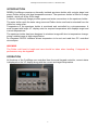
CONFIDENTIAL DOCUMENT – NOT FOR GENERAL RELEASE
Coolstage MK3 Specimen
Cooling Unit
Technical Manual
Version 3.11
November 2009
Deben UK Limited, Brickfields Business Park, Woolpit, Bury St. Edmunds, Suffolk IP30 9QS, UK.
Tel: +44 (0) 1359 244 870, Fax: +44 (0) 1359 244 879
E-mail: [email protected], Website: www.deben.co.uk
CoolStage Technical manual Version 3.11 November 2009
Contents
Description
Page number
Operation manual
2
Technical description
8
Service information
12
Circuit diagrams
14
Port plate cable connections
15
System wiring diagram
16
Control PCB schematic
17
Pump/valve control schematic
18
Microprocessor schematic
19
Coolstage controller
20
External wiring loom cable
21
Internal head unit cable
22
Internal RS-232 cable
23
Internal pump control cable
24
Revision history:
3.00 – March 2005
3.10 – November 2005
3.11 – November 2009, Delrin waterbox information added
1
CoolStage Technical manual Version 3.11 November 2009
Coolstage, specimen cooling unit operation manual scu3.01
CONTENTS
FUNCTION
Introduction
Operation
Setting temperature
Photo mode
Sample exchange
Command Summary
Appendix -A (storage)
Appendix -B (Water pipe connection)
Appendix -C (Refilling waterbox)
PAGE
3
3
4
4
4
5
6
6
7
2
CoolStage Technical manual Version 3.11 November 2009
INTRODUCTION
DEBEN CoolStage comprises a thermally isolated specimen holder with a single stage heat
pump (Peltier device) and dual temperature sensor. The specimen holder is fitted to a stage
adapter, which will fit the JEOL stage.
A vacuum feedthrough flange provides power and water connections to the specimen holder.
The water chiller cools the water using a second Peltier device and heat is extracted from the
chiller box using a fan.
Temperature of the specimen holder is monitored and controlled by a microprocessor. A
small keypad with bright VF display sets the required temperature and displays target and
current temperatures.
The specimen holder has been designed to minimise image drift due to temperature change,
giving a stable image at high magnification.
An integrated RS-232 interface allows temperature to be set and read from PC controlled
microscopes.
WARNING
The Peltier cold head is fragile and care should be taken when handling. If dropped the
performance may be degraded.
OPERATION
All functions of the CoolStage are controlled from the small keypad controller, current status
is displayed on the VF display along with the current and target temperature.
3
CoolStage Technical manual Version 3.11 November 2009
SETTING TEMPERATURE
When the system is switched on temperature control of the specimen will be off but the water
will be chilled, therefore the specimen holder will be chilled to about 8ºC below ambient
temperature.
At any time after heating or cooling the off button may be pressed which will switch off the
specimen Peltier device and the specimen holder will slowly reach 8ºC below ambient
temperature.
To set the specimen holder temperature press auto, required temperature is then adjusted
using the up/down arrow keys. As an alternative the goto key allows the target temperature
to be entered from the keypad (using the numeral keys). Maximum cooling rate is 35°C/min
and maximum heating rate is 25ºC/min. At the upper and lower end of the temperature range
cooling/heating rate will be much lower.
Temperatures in the range of -30ºC to +50ºC or -10ºF to +120ºF may be set.
Minimum temperature (-30ºC) will only be obtainable when operating under vacuum of at
least 50pa, at 300pa we guarantee at least -25ºC. Normally only approximately -20ºC will be
possible at atmospheric pressure (and then only with ambient of 15ºC or below).
When using the CoolStage to look at wet samples you should start to cool the specimen
holder just before pumping the chamber, the exact time will depend on the sample, the
microscope and environmental conditions (ambient temperature). An initial amount of
experimentation will be necessary to determine the exact timing required.
IMPORTANT NOTE
The CoolStage chassis should be switched on for around 30 minutes before use, to allow the
cooling water to reach the correct temperature.
PHOTO MODE
The photo button is for use when taking a photo on the SEM to ensure that no image shift is
seen on the resultant image. To use, select the required temperature and when the
temperature has been reached press the photo button and the current through the Peltier
device will be fixed. You will see a slight change in temperature of approximately 0.1º per
minute - (this is normal). After taking the photo press the auto button and the CoolStage will
switch back to controlling the temperature as normal.
IMPORTANT NOTE:
Do not press photo while the temperature is still increasing or decreasing, otherwise the
Peltier current will be fixed at this level and will not stop at the desired level but continue
rising or falling.
SAMPLE EXCHANGE
When exchanging the sample or bringing the vacuum chamber up to atmosphere pressure
after using the CoolStage at temperatures below ambient, you should first increase the
specimen holder temperature to ensure that condensation does not form on the
specimen/specimen holder.
The exch button will automatically take the specimen holder temperature to a programmable
temperature from between 5ºC to 20ºC.
4
CoolStage Technical manual Version 3.11 November 2009
COMMAND SUMMARY
off
- Switches Peltier device off (cooling or heating). Sample will slowly reach
ambient temperature.
auto - Sets the controller to control the sample temperature. The required temperature
is set using the up/down keys on the controller. Normally the increment is 0.5ºC
goto - Temperature can be entered from the keypad. The delete key acts as the
minus key. Acceptable values lie in the range of -25ºC to +50ºC or -10ºF to +120ºF.
step - Toggles the increment for temperature setting, 0.5º is the default but it can be
toggled to 0.1º.
up/down - Increases or decreases the set temperature.
cal
- Setup and display routines:
1 - displays the Peltier device current
2 - hides the Peltier device current
3 - displays the heatsink temperature
4 - sets the sample exchange
7 - sets the temperature control loop
8 - sets manual mode (only operates if
(default)
(typically 20-30ºC).
temperature (5-20ºC).
gain (default = 6).
Peltier device is switched off first).
photo - Switches off the closed loop temperature control. The Peltier device current will
remain constant, although the temperature may change slightly.
exch - sets the sample temperature to the pre-programmed exchange temperature.
ºC/ºF - changes the temperature display from degrees Centigrade to Fahrenheight.
del
- cancel or minus key
enter - accept
5
CoolStage Technical manual Version 3.11 November 2009
Appendix - A - storage of CoolStage
When CoolStage is not fitted to the Microscope it should be fitted to the supplied mounting
block to ensure safe keeping. The port plate will slot into a slot and a hole is provided for the
specimen holder. If required, the releasable tie-wraps (supplied) can be used to secure the
parts in place as shown below.
WARNING
The Peltier cold head is fragile and care should be taken when handling. If dropped the
performance may be degraded.
Appendix - B – Connecting/disconnecting water pipes and coolhead cable.
The unit is fitted with quick release connections for the coolhead water pipes and power
cable.
To connect up the water pipes simply push them on and the connectors should lock into
place Note: It does not matter which pipe is connected to which. To connect up the coolhead
power cable; line up the slot on the plug to the location pin at the top of the socket (mounted
on the front of the chassis) and then simply push the plug in and it should lock into place.
To disconnect the coolhead water pipes and cable simply pull on the quick release latches
and the connectors should easily come off. Note: Do not remove connections when system is
on. The valves will automatically shut off if the water pipes are disconnected when the
system is on. However, a small amount of water may be lost due to the time taken for the
valves to close fully. For this reason it is important that the system is switched off before
removing any connectors.
6
CoolStage Technical manual Version 3.11 November 2009
Appendix - C – Refilling waterbox
Over time there may be some water lost in the cooling unit through evaporation and the
removal of the water pipe connections. Because of this the chiller/PSU unit has been fitted
with a water level sensor. When the waterbox needs to be refilled the water level LED
(located on the front of the unit) will illuminate and the pump will automatically cut out. While
the unit is in this state cooling/heating of samples will not be possible. The waterbox will need
to be topped up before the unit will function again.
To refill the waterbox firstly remove water refill cover (using 2mm ball driver provided) located
on top of the chiller/PSU unit (see fig. 1). Then remove the silver top insulation cover (see fig.
2) – Not present on delrin version.
Undo the four screws holding on the waterbox lid with the 3mm ball driver provided. Remove
the brass waterbox lid. Note: If the lid will not come off easily then undo the pressure release
screw (see fig. 3) with the 2.5mm ball driver provided. Once the waterbox lid is off re-insert
screw and make sure the o-ring is still located under screw head. Refill waterbox (use deionised water only) as shown in fig. 4. Note: Do not over fill waterbox. Fill only up to top of the
edge where the o-ring is seated (see fig. 5). Replace brass waterbox lid, silver top insulation
cover and water refill cover.
Brass waterbox, 2004-2009:
Fig. 1
Fig. 2
Fig. 3
Fig. 4
Fig. 5
Delrin waterbox, 2009 onwards:
Fig. 1
Fig. 3
Fig. 4
7
Fig. 5
CoolStage Technical manual Version 3.11 November 2009
CoolStage MK3
Specimen Cooling Unit
Technical information
© Deben UK Ltd. 1999-2009
8
CoolStage Technical manual Version 3.11 November 2009
Coolstage MK3 water cooling block diagram
Basic system description
The system is microprocessor controlled and temperature can be set and read from a compact keypad
controller. The system can be controlled by RS-232 in parallel or in place of the keypad controller.
The water reservoir contains approximately one litre of water which is cooled by a high power peltier chip. The
hot side of the peltier is fixed to a large heatsink which is in turn air cooled by a mains powered fan.
A magnetically coupled mains powered water pump circulates the water from the reservoir to the cold head
where it is used to cool the hot side of the specimen cooling peltier. A level sensor monitors water level and
illuminates a red LED when the water tank requires filling. In case of a water leak the motorised valves will shut
off the water supply in less than one second. A filter is fitted in the water pipe after the pump to reduce vibration
being transmitted through the water to the specimen holder.
Two NTC thermistors monitor the temperature of the specimen and temperature of the water at the coolhead if
the temperature of the water at the coolhead goes above 30°C the power to the peltier will automatically
switched off and an over temperature warning displayed on the keypad display.
9
CoolStage Technical manual Version 3.11 November 2009
MK3 Coolhead is shown below:
Cross section of Coolhead:
10
CoolStage Technical manual Version 3.11 November 2009
Rear panel of Coolstage showing water level indicator LED, if this LED illuminated the water tank should be
refilled:
Electronics layout, 2004 - 2009:
11
CoolStage Technical manual Version 3.11 November 2009
Electronics layout, 2009 onwards:
12
CoolStage Technical manual Version 3.11 November 2009
Coolstage MK3 Service Information
The following information has been gathered to provide a basic understanding of the Coolstage
system and to allow a technical person to carry out some basic maintenance.
Problem
Solution
Noise from the pump
Sometimes when a system has been in transit an air pocket can
develop in the pump causing the pump to be noisy. Normally running
the system for around one hour will solve this problem. Switching the
system on and off a number of times will sometimes help to purge the
air.
Alarm sounds
If the cold head heatsink temperature exceeds 30ºC then the system
will display an over temperature warning and shut down automatically to
protect the peltier device from damage. This can be caused by the room
temperature being too high (>30ºC) or by the water flow being too low.
Check the water level – see instructions 2 pages ahead. Also check the
pump is working.
No characters
on keypad display
Check you have mains power, is the fan running?, check mains fuse.
If the system seems to work even though the display does not light up
then it may be just the display it’s self – we have had some failures,
contact Deben for an exchange keypad.
Vacuum level is bad
The systems are tested to 1x10⁻³ Pa and should achieve this vacuum
quickly. If this is not possible there may be a small leak on one of the
internal water pipes. The design of these pipes was modified in March
2002 to solve this problem. Contact Deben if you think you have a
problem with these pipes.
Fan not working
Check that both fan is operating. The lifetime of the fan will depend on
the operating voltage and operation time. 3 years of continuous
operation is average lifetime.
Unable to achieve low
Low temperature.
Room temperature should be <25ºC, at this ambient temperature you
Should achieve –25ºC at 300Pa. You should also make sure the cooling
unit is not sitting in a direct hot air flow (eg. Directly next to the SEM
electronics vent. Check the water is at a good temperature (press CAL,
3), normal temperature should be below 25ºC. If the temperature is
above this then you have a problem. You should allow the system to
stand for at least 30 minutes before operating to allow the water time to
cool. The Peltier on the cold head is fragile and will break if dropped, it
could look OK but be broken internally. If the heatsink temperature is
low (<25ºC) and ambient is <25ºC then you should get –25ºC at 300Pa,
if not then the Peltier may be damaged. Contact Deben for more help.
13
CoolStage Technical manual Version 3.11 November 2009
Coolstage Wiring connections & pipe lengths
Updated 15/09/05
Port plate cable connections:
Internal pipe length – This is the cut length allowing 10mm for clamping at the port plate
Hitachi S-3000/3500
Hitachi S-3400/4300
Hitachi S-3600
320mm
365mm
600mm
JEOL 6360/6480
290mm
(same for 5600/5900)
Zeiss 1400/EVO
Zeiss SUPRA
355mm
700mm
(same for LEO 440, 1420 & 1500)
Shimadzu
350mm
14
CoolStage Technical manual Version 3.11 November 2009
CoolStage
Specimen Cooling Unit
Circuit Diagrams
Please contact Deben with system serial number if additional circuit diagrams are required.
© Deben UK Ltd. 1999-2009
15