1
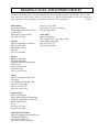
Agilent 16064B LED Display/Trigger Box
Operation and Service Manual
Agilent Part No. 16064-90010
Printed in JAPAN March 2000
Second Edition
Notice
The information contained in this document is subject to change without notice.
This document contains proprietary information which is protected by copyright. All rights are
reserved. No part of this document may be photocopied, reproduced, or translated to another
language without the prior written consent of the Agilent Technologies.
Agilent Technologies Japan, Ltd.
Component Test PGU-Kobe
1-3-2, Murotani, Nishi-ku, Kobe-shi,
Hyogo, 651-2241 Japan
Warranty
This Agilent Technologies instrument product is warranted against defects in material and
workmanship for a period of one year from the date of shipment, except that in the case of
certain components listed in this manual, the warranty shall be for the specied period. During
the warranty period, Agilent Technologies will, at its option, either repair or replace products
which prove to be defective.
For warranty service or repair, this product must be returned to a service facility designed by
Agilent Technologies. The Buyer shall prepay shipping charges to Agilent Technologies and
Agilent Technologies shall pay shipping charges to return the product to the Buyer. However,
the Buyer shall pay all shipping charges, duties, and taxes for products returned to Agilent
Technologies from another country.
Agilent Technologies warrants that its software and rmware designed by Agilent Technologies
for use with an instrument will execute its programming instruction when property installed on
that instrument. Agilent Technologies does not warrant that the operation of the instrument,
or software, or rmware will be uninterrupted or error free.
Limitation of Warranty
The foregoing warranty shall not apply to defects resulting from improper or inadequate
maintenance by the Buyer, Buyer-supplied software or interfacing, unauthorized modication
or misuse, operation outside of the environmental specications for the product, or improper
site preparation or maintenance.
No other warranty is expressed or implied. Agilent Technologies specically disclaims the
implied warranties of merchantability and tness for a particular purpose.
Certication
The Agilent Technologies certies that this product met its published specications at the
time of shipment from the factory. Agilent Technologies further certies that its calibration
measurements are traceable to the United States National Institute of Standards and
Technology, to the extent allowed by the Institute's calibration facility, or to the calibration
facilities of other International Standards Organization members.
Exclusive Remedies
The remedies provided herein are the buyer's sole and exclusive remedies. Agilent Technologies
shall not be liable for any direct, indirect, special, incidental, or consequential damages,
whether based on contract, tort, or any other legal theory.
Assistance
Product maintenance agreements and other customer assistance agreements are available for
Agilent Technologies products.
If you need assistance, contact your nearest Agilent Technologies Sales and Service Oce.
Addresses are provided at the back of this manual.
c Copyright 1991, 2000 Agilent Technologies Japan, Ltd.
Manual Printing History
The manual printing date and part number indicate its current edition. The printing date
changes when a new edition is printed. (Minor corrections and updates which are incorporated
at reprint do not cause the date to change.) The manual part number changes when extensive
technical changes are incorporated.
November 1991 : : : : : : : : : : : : : : : : : : : : : : : : : : : : : : : : : : : : : : First Edition (part number: 16064-90010)
March 2000 : : : : : : : : : : : : : : : : : : : : : : : : : : : : : : : : : : : : : : : : Second Edition (part number: 16064-90010)
iv
Safety Summary
The following general safety precautions must be observed during all phases of operation,
service, and repair of this instrument. Failure to comply with these precautions or with specic
WARNINGS given elsewhere in this manual violates safety standards of design, manufacture,
and intended use of the instrument.
The Agilent Technologies assumes no liability for the customer's failure to comply with these
requirements.
Do NOT operate in an Explosive Atmosphere
Do not operate the instrument in the presence of ammable gasses or fumes. Operation of any
electrical instrument in such an environment constitutes a safety hazard.
Keep Away from Live Circuits
Operating personnel must not remove instrument covers. Component replacement and
internal adjustments must be made only by qualied maintenance personnel. Do not replace
components with the power cable connected. Under certain conditions, dangerous voltages
may exist even with the power cable removed. To avoid injury, always disconnect power and
discharge circuits before touching them.
Do NOT Service or Adjust While Alone
Do not attempt internal service or adjustment unless another person, capable of turning o
power and capable of rendering rst aid and resuscitation, is present.
Do NOT Substitute Parts or Modify Instrument
Because of the danger of introducing additional hazards, do not substitute parts or perform
unauthorized modications to the instrument. Return the instrument to a Agilent Technologies
Sales and Service Oce for service and repair to ensure the safety features are maintained.
Dangerous Procedure Warnings
Warnings, such as the example below, precede POTENTIALLY DANGEROUS PROCEDURES
throughout this manual. Instructions contained in the warnings must be followed.
Warning
Dangerous voltages, capable of causing death, are present in this
instrument. Use extreme caution when handling, testing, and adjusting
this instrument.
v
Safety Symbols
General denitions of safety symbols used on equipment or in manuals.
Instruction manual symbol: the product will be marked with this symbol when
it is necessary for the user to refer to the instruction manual in order to
protect against damage to the instrument.
Indicates dangerous voltage (terminals fed from the interior by voltage
exceeding 1000 volts must be so marked).
Protective ground terminal. For protection against electrical shock in case of
a fault in the instrument. Used with wiring terminals to indicate the terminal
which must be connected to ground before operating equipment.
Low-noise or noiseless, clean ground (earth) terminal. Used for a signal
common, as well as providing protection against electrical shock in case
of a fault in the instrument. A terminal marked with this symbol must be
connected to ground in the manner described in the installation (Operation)
manual, and before operating the equipment.
Frame or chassis terminal. A connection to the frame (chassis) of the
equipment which normally includes all exposed metal structures.
Alternating current (power line).
Direct current (power line).
Alternating or direct current (power line).
Warning denotes a hazard. It calls attention to a procedure, practice, condition
or the like, which, if not correctly performed or adhered to, could result in
injury or death to personnel.
Caution sign denotes a hazard. It calls attention to a procedure, practice,
condition or the like, which, if not correctly performed or adhered to, could
result damage to or destruction of part or all of the product.
Note denotes important information. It calls attention to a procedure, practice,
condition or the like, which is essential to highlight.
vi
Contents
1. General Information
Introduction . . . . . . . . . .
Using the 16064B . . . . . . .
Product Description . . . . . .
Accessories Supplied . . . . . .
Operating and Safety Precautions
Operating . . . . . . . . . .
Service . . . . . . . . . . .
Specications . . . . . . . . .
.
.
.
.
.
.
.
.
.
.
.
.
.
.
.
.
.
.
.
.
.
.
.
.
.
.
.
.
.
.
.
.
.
.
.
.
.
.
.
.
.
.
.
.
.
.
.
.
.
.
.
.
.
.
.
.
.
.
.
.
.
.
.
.
.
.
.
.
.
.
.
.
.
.
.
.
.
.
.
.
.
.
.
.
.
.
.
.
.
.
.
.
.
.
.
.
.
.
.
.
.
.
.
.
.
.
.
.
.
.
.
.
.
.
.
.
.
.
.
.
.
.
.
.
.
.
.
.
.
.
.
.
.
.
.
.
.
.
.
.
.
.
.
.
.
.
.
.
.
.
.
.
.
.
.
.
.
.
.
.
.
.
.
.
.
.
.
.
.
.
.
.
.
.
.
.
.
.
.
.
.
.
.
.
1-1
1-1
1-1
1-2
1-2
1-2
1-2
1-3
Introduction . . . . . . . . . . . . . . .
Initial Inspection . . . . . . . . . . . . .
Environmental Considerations . . . . . .
Operating and Storage . . . . . . . . .
Connecting the Box for Use . . . . . . .
Repackaging the LED Display/Trigger Box .
.
.
.
.
.
.
.
.
.
.
.
.
.
.
.
.
.
.
.
.
.
.
.
.
.
.
.
.
.
.
.
.
.
.
.
.
.
.
.
.
.
.
.
.
.
.
.
.
.
.
.
.
.
.
.
.
.
.
.
.
.
.
.
.
.
.
.
.
.
.
.
.
.
.
.
.
.
.
.
.
.
.
.
.
.
.
.
.
.
.
.
.
.
.
.
.
.
.
.
.
.
.
.
.
.
.
.
.
2-1
2-1
2-2
2-2
2-3
2-3
Introduction . . . . . . . . . . . . . . . . . . . . . . . . . . .
Operation . . . . . . . . . . . . . . . . . . . . . . . . . . . .
How to Trigger a Measurement form the LED Display/Trigger Box
How to Use the LED Indicator related to the Comparator . . . .
How to Clear the LED Indicator related to the Comparator . . . .
How to Use the Contact Check LED Indicator . . . . . . . . . .
.
.
.
.
.
.
.
.
.
.
.
.
.
.
.
.
.
.
.
.
.
.
.
.
.
.
.
.
.
.
.
.
.
.
.
.
3-1
3-3
3-3
3-3
3-3
3-3
Introduction . . . . . . . . . . . . . . . . . . . . . . . . . . . . . . . . .
Replaceable Parts . . . . . . . . . . . . . . . . . . . . . . . . . . . . . .
Schematic Diagram . . . . . . . . . . . . . . . . . . . . . . . . . . . . .
4-1
4-2
4-6
2. Preparation for Use
3. Operation
4. Service
Contents-1
Figures
2-1.
2-2.
3-1.
4-1.
4-2.
4-3.
Product Overview . . . . .
Connecting the Cable . . .
16064B Features . . . . . .
Replaceable Parts Identier .
Component Locations . . .
Schematic Diagram . . . .
.
.
.
.
.
.
.
.
.
.
.
.
.
.
.
.
.
.
.
.
.
.
.
.
.
.
.
.
.
.
.
.
.
.
.
.
.
.
.
.
.
.
.
.
.
.
.
.
.
.
.
.
.
.
.
.
.
.
.
.
.
.
.
.
.
.
.
.
.
.
.
.
.
.
.
.
.
.
.
.
.
.
.
.
.
.
.
.
.
.
.
.
.
.
.
.
.
.
.
.
.
.
.
.
.
.
.
.
.
.
.
.
.
.
.
.
.
.
.
.
.
.
.
.
.
.
.
.
.
.
.
.
.
.
.
.
.
.
.
.
.
.
.
.
2-2
2-3
3-1
4-2
4-5
4-6
Furnished Accessories . . . . . . . .
Contents . . . . . . . . . . . . . .
Applicable Instrument to the Indicators
Replaceable Parts . . . . . . . . . .
Replaceable Parts on PC Board (1 of 2)
.
.
.
.
.
.
.
.
.
.
.
.
.
.
.
.
.
.
.
.
.
.
.
.
.
.
.
.
.
.
.
.
.
.
.
.
.
.
.
.
.
.
.
.
.
.
.
.
.
.
.
.
.
.
.
.
.
.
.
.
.
.
.
.
.
.
.
.
.
.
.
.
.
.
.
.
.
.
.
.
.
.
.
.
.
.
.
.
.
.
.
.
.
.
.
1-2
2-2
3-2
4-3
4-4
Tables
1-1.
2-1.
3-1.
4-1.
4-2.
Contents-2
1
General Information
Introduction
The purpose of this manual is to enable you to use your 16064B LED Display/Trigger Box
eciently and condently. This manual contains both general and specic information. To
use the 16064B to perform a specic function (without reading the entire manual), follow the
directions in \Using the 16064B".
Using the 16064B
The 16064B has been designed to operate specically with the 4263B LCR Meter, 4338B
Milliohmmeter and 4339B High Resistance Meter.
To install the 16064B, turn to Chapter 2.
To operate the 16064B, turn to Chapter 3.
To order replaceable parts for the 16064B, turn to \Replaceable Parts" in Chapter 4.
Product Description
The 16064B has been designed to operate specically with the 4263B LCR Meter, 4338B
Milliohmmeter and 4339B High Resistance Meter. The 16064B has the following four functions:
To display the results sent from the 4263B, 4338B, and 4339B comparator by LEDs through
the handler interface.
To display an indicator, which shows that the internal protection circuit of the instrument is
prohibiting a measurement to avoid erroneous operation.
To lock out the front panel keys of instrument.
To trigger a measurement.
General Information
1-1
Accessories Supplied
The following is a list of the accessories supplied with the 16064B:
Table 1-1. Furnished Accessories
Description
Part Number
Operation and Service Manual
P/N 16064-90010
Quantity
1
Operating and Safety Precautions
Operating
You need observe only normal precautions in handling and operating the 16064B.
Caution
Electrostatic discharge (esd) can damage the highly sensitive microcircuits in
the 16064B LED Display/Trigger Box. ESD damage is most likely to occur as
the boxes are connected or disconnected. Protect them by wearing a grounding
strap that provides a high resistance path to ground. Alternatively, ground
yourself by touching the outer shell of any grounded instrument chassis before
touching the test port connectors.
Never touch the center contacts of the connectors.
Use a work station equipped with an anti-static surface.
Service
The voltages levels in this product do not warrant more than normal caution for operator
safety. Nevertheless, service should be performed only by qualied personnel.
1-2
General Information
Specications
This section lists the complete 16064B specications. These specications are the performance
standards and limits against which the 16064B is tested. When shipped from the factory, the
16064B meets the specications listed in this section.
Applicable Instrument : : : : : : : : : : : : : : : : : : : : : : : : : : : : : : : : : : : : : : : : : : : : : : : : 4263B, 4338B, and 4339B
Parameter Displayed : : : : : : : : : : : : : : : : : : : : : : : : : : : : : : : : : : : : : : : : : : : : : : : : : : : : : : High, In, Lo (primary)
: : : : : : : : : : : : : : : : : : : : : : : : : : : : : : : : : : : : : : : : : : : : : : : : : : : : : : : : : : : : : : : : : : : : : : : : : : High, In, Lo (secondary)
: : : : : : : : : : : : : : : : : : : : : : : : : : : : : : : : : : : : : : : : : : : : : : No Contact 1 , Over Current 2, Over Voltage (Fail) 3
Input Signal Controlled : : : : : : : : : : : : : : : : : : : : : : : : : : : : : : : : : : : : : : : : : : : : : : : : : : : : : : : : : : : : : : : : EXT TRG
Maximum VA : : : : : : : : : : : : : : : : : : : : : : : : : : : : : : : : : : : : : : : : : : : : : : : : : : : : : : : : : : : : : : : : : : : 5 V, 120 mA max
Cable Length : : : : : : : : : : : : : : : : : : : : : : : : : : : : : : : : : : : : : : : : : : : : : : : : : : : : : : : : : : : : : : : : : : : : : : : : : : : : : : : 1.5 m
Operating Temperature : : : : : : : : : : : : : : : : : : : : : : : : : : : : : : : : : : : : : : : : : : : : : : : : : : : : : : : : : : : : : : : : 0 to 55 C
Operating Humidity : : : : : : : : : : : : : : : : : : : : : : : : : : : : : : : : : : : : : : : : : : : : : : : : 95% RH (@40 C, 24 hours)
Non-operating Temperature : : : : : : : : : : : : : : : : : : : : : : : : : : : : : : : : : : : : : : : : : : : : : : : : : : : : : : : : 040 to 70 C
Non-operating Humidity : : : : : : : : : : : : : : : : : : : : : : : : : : : : : : : : : : : : : : : : : : : 95% RH (@65 C, 24 hours)
Dimensions : : : : : : : : : : : : : : : : : : : : : : : : : : : : : : : : : : : : : : : : : : : : : 200 mm (w) 2 40 mm (h) 2 100 mm (d)
Weight : : : : : : : : : : : : : : : : : : : : : : : : : : : : : : : : : : : : : : : : : : : : : : : : : : : : : : : : : : : : : : : : : : : : : : : : : : : : : : : : : : : : : 0.8 kg
1
Result of Contact Check function of 4339B and 4263B.
2
This is displayed when the Current Limit function of 4339B detects that the current
through the DUT is over the limit.
3
This is displayed when the voltage limit function of 4338B detects that the voltage applied
to the DUT is over 20 mV peak.)
General Information
1-3
2
Preparation for Use
Introduction
This chapter explains how to install the 16064B LED Display/Trigger Box. The topics covered
include initial inspection, environment considerations, connecting the cable for use, and
repackaging the LED Display/Trigger Box.
Initial Inspection
The LED Display/Trigger Box has been carefully inspected electrically and mechanically before
being shipped from the factory. It should be in perfect physical condition, no scratches,
dents or the like, and it should be in perfect electrical condition. Verify this by carefully
performing an incoming inspection to check the box for signs of physical damage and missing
contents. If any discrepancy is found, notify the carrier and Agilent Technologies. Your Agilent
Technologies sales oce will arrange for repair and replacement without waiting for the claim
to be settled.
1. Inspect the shipping container for damage, and keep the shipping materials until the
incoming inspection is completed.
2. Verify that the shipping container contains everything shown in Figure 2-1 and listed in
Table 2-1.
3. Inspect the exterior of the 16064B for any signs of damage.
Preparation for Use
2-1
Figure 2-1. Product Overview
Table 2-1. Contents
Agilent Part Number
Description
1 LED Display/Trigger Box
2 Operation and Service Manual2
1 Agilent
16064-600031
16064-90010
Quantity
1
1
internal-only part number.
2 Operation
and Service Manual is not shown in Figure 2-1.
Environmental Considerations
Operating and Storage
The 16064B should be operated within an ambient temperature range of 0 C to 55 C and
relative humidity up to 95% at 40 C (non-condensing).
The 16064B may be stored within a temperature range of 040 C to +70 , and at a relative
humidity of up to 95% at +65 C (non-condensing).
2-2
Preparation for Use
Connecting the Box for Use
Note
When 16064B is used, the handler interface of 4263B, 4338B, and 4339B should
be the factory setting as follows:
Factory Setting of the Handler Interface
Ext DCV2 is from 5 volt through 6 volt
No pull-up resistors
See 4263B Operation Manual, 4338B Operation Manual, and 4339B Operation
Manual for more information on how to set up the handler interface board.
Figure 2-2. Connecting the Cable
Repackaging the LED Display/Trigger Box
If shipping to a Agilent Technologies service center is required, each box should be repackaged
using the original factory packaging materials.
Alteratively, comparable packaging materials may be used. Wrap the box in heavy paper and
pack in anti-static plastic packing material. Use sucient shock absorbing material on all sides
of the 16064B to provide a thick, rm cushion and to prevent movement. Seal the shipping
container securely and mark it FRAGILE.
Preparation for Use
2-3
3
Operation
Introduction
This chapter illustrates the features of the 16064B(Figure 3-1) describes what the indicators
show, how to lock out the front keys of instrument, and how trigger to a measurement.
Figure 3-1. 16064B Features
1. Primary result indicator (LOW). Turns ON when the primary parameter measurement
result, sent from the comparator, is LOW.
2. Primary result indicator (IN). Turns ON when the primary parameter measurement result,
sent from the comparator, is IN.
3. Primary result indicator (HIGH). Turns ON when the primary parameter measurement
result, sent from the comparator, is HIGH.
4. Secondary result indicator (LOW). Turns ON when the secondary parameter measurement
result, sent from the comparator, is LOW.
Operation
3-1
5. Secondary result indicator (IN). Turns ON when the secondary parameter measurement
result, sent from the comparator, is IN.
6. Secondary result indicator (HIGH). Turns ON when the secondary parameter measurement
result, sent from the comparator, is HIGH.
7. Over current indicator. Turns ON when the current owing through the DUT is over the
limit and the instrument can not measure the DUT.
8. Over voltage indicator. Turns ON when the measurement voltage across the DUT is over
the limits and the instrument can not measure the DUT.
9. No contact indicator. Turns ON when the contact check function detects a broken cable or
a bad connection.
10. Key lock switch. Turning this ON disables the front panel key input.
11. Trigger key. Pressing this triggers a measurement.
Warning
When the 16064B is connected to the 4339B, DO NOT touch the
UNKNOWN connector when you pressing the trigger key. The trigger key
causes that the 4339B supplies high voltage up to 1000 Vdc maximum to
the UNKNOWN connector when the sequence measurement is turned to
ON. The High Voltage Indicator of the 4339B is lit while the high voltage
is supplied. You must operate connecting the test xture to the 4339B
after turning o the voltage output and making conrmation of the high
voltage indicator is turned OFF.
12. Connection Cable. This should be connected to the handler interface terminal on the rear
panel of the instrument.
Each instrument connected to 16064B can only use the LED indicators related to the functions
that the instrument provides. In the following table, each instrument can use the LED
indicators marked by \".
Table 3-1. Applicable Instrument to the Indicators
LED Indicator
4338B
4339B
4263B
(1) Primary LOW
(2) Primary IN
(3) Primary HIGH
(4) Secondary LOW
(5) Secondary IN
(6) Secondary HIGH
(7) Over Current
(8) Over Voltage
(9) No Contact
Note
3-2
Operation
When the Key Lock switch of the 16064B is turned on, front panel key input
is disabled even if the Key Lock key on the front panel of the instrument is
pressed or the GPIB command SYST:KLOC OFF (Key Lock OFF) is sent by GPIB.
Operation
How to Trigger a Measurement form the LED Display/Trigger Box
Warning
When the 16064B is connected to the 4339B, DO NOT touch the
UNKNOWN connector when you pressing the trigger key. The trigger key
causes that the 4339B supplies high voltage up to 1000 Vdc maximum to
the UNKNOWN connector when the sequence measurement is turned to
ON. The High Voltage Indicator of the 4339B is lit while the high voltage
is supplied. You must operate connecting the test xture to the 4339B
after turning o the voltage output and making conrmation of the high
voltage indicator is turned OFF.
1. Set the trigger mode to the EXT Trig mode from the front keys of the instrument.
2. Press the trigger key of the 16064B.
Note
In EXT Trig mode, you can use both the trigger key of 16064B or the EXT
Trigger terminal on the rear panel of the instrument to trigger it. The
instrument is triggered by a fast pulse input, either from the trigger key of the
box or from the EXT Trigger terminal.
How to Use the LED Indicator related to the Comparator
Turn on the comparator function from the front panel key of the instrument.
How to Clear the LED Indicator related to the Comparator
Turn OFF the comparator function using the front panel keys of the instrument.
How to Use the Contact Check LED Indicator
Turn ON the contact check function using the appropriate front panel key of the instrument.
Operation
3-3
4
Service
Introduction
This chapter gives service information for the 16064B. The Replaceable Parts List and the
Schematic Diagram are included.
Service
4-1
Replaceable Parts
Figure 4-1 and Table 4-1 identify the replaceable parts. Figure 4-2 and Table 4-2 identify the
replaceable parts on the PC board. The parts listed can be ordered from your nearest Agilent
Technologies oce. Ordering information should include the Agilent Part number and the
quantity required.
Figure 4-1. Replaceable Parts Identier
4-2
Service
Reference
Designator
1
2
3
4
5
6
7
8
9
10
11
Table 4-1. Replaceable Parts
Agilent Part
Number
Qty.
Description
16064-04403
16064-66503
16064-04004
0403-0424
16064-61611
0515-1550
0515-0914
0515-0914
16064-00602
0515-2079
1400-0014
1400-0493
1
1
1
4
1
4
4
2
1
1
1
1
Cover Top
PC Board Assembly
Cover Bottom
Cushion 20.627.6
Cable Assembly
Screw Pan Head M320.5 L8
Screw Flat Head M320.5 L6
Screw Flat Head M320.5 L6
Angle
Screw Pan Head M4 L8
Cable Clamp
Cable Tie
Service
4-3
Reference
Designator
A1
A1C1
A1C2
A1C3
A1C4
A1C5
A1DS1
A1DS2
A1DS3
A1DS4
A1DS5
A1DS6
A1DS7
A1DS8
A1DS9
A1J1
A1R1
A1R2
A1R3
A1R4
A1R5
A1R6
A1R7
A1R8
A1R9
A1R10
A1R11
A1R12
A1R13
A1R14
A1R15
A1R16
A1R17
A1R18
A1R19
A1R20
A1R21
4-4
Service
Table 4-2. Replaceable Parts on PC Board (1 of 2)
Agilent Part C
Number
D Qty.
Description
16064-66503
0160-4835
0160-6561
0160-6561
0180-3597
0160-4832
1990-0534
1990-0521
1990-0534
1990-0534
1990-0521
1990-0534
1990-0487
1990-0487
1990-0487
1251-5653
0698-3155
0698-3155
0698-3155
0698-3155
0698-3155
0698-3155
0698-3155
0698-3155
0698-3155
0698-0082
0698-0082
0698-0082
0698-0082
0698-0082
0698-0082
0698-0082
0698-0082
0698-0082
0698-3155
0757-0280
0698-3454
1
7
0
0
8
4
5
0
5
5
0
5
7
7
7
3
1
1
1
1
1
1
1
1
1
7
7
7
7
7
7
7
7
7
1
3
3
1
1
1
1
1
1
1
1
1
1
1
1
1
1
1
1
1
1
1
1
1
1
1
1
1
1
1
1
1
1
1
1
1
1
1
1
1
PC BOARD ASSEMBLY
CAP-FXD 0.1F 610% 50 V
CAP-FXD 0.1F 620% 50 V
CAP-FXD 0.1F 620% 50 V
CAP-FXD 47F 620% 25 V
CAP-FXD 0.01F 610% 100 V
LED-LAMP
LED-LAMP
LED-LAMP
LED-LAMP
LED-LAMP
LED-LAMP
LED-LAMP
LED-LAMP
LED-LAMP
CONNECTOR-POST TYPE
RESISTOR 4.64K 61% 0.125W
RESISTOR 4.64K 61% 0.125W
RESISTOR 4.64K 61% 0.125W
RESISTOR 4.64K 61% 0.125W
RESISTOR 4.64K 61% 0.125W
RESISTOR 4.64K 61% 0.125W
RESISTOR 4.64K 61% 0.125W
RESISTOR 4.64K 61% 0.125W
RESISTOR 4.64K 61% 0.125W
RESISTOR 464 61% 0.125W
RESISTOR 464 61% 0.125W
RESISTOR 464 61% 0.125W
RESISTOR 464 61% 0.125W
RESISTOR 464 61% 0.125W
RESISTOR 464 61% 0.125W
RESISTOR 464 61% 0.125W
RESISTOR 464 61% 0.125W
RESISTOR 464 61% 0.125W
RESISTOR 4.64K 61% 0.125W
RESISTOR 1K 61% 0.125W
RESISTOR 215K 61% 0.125W
Reference
Designator
A1SW1
A1SW2
A1U1
A1U2
A1U3
A1MP1
A1MP2
A1MP3
A1MP4
Replaceable Parts on PC Board (2 of 2)
Agilent Part C
Number
D Qty.
Description
3101-3064
3101-2334
1820-3707
1820-3145
1820-1423
0371-3804
94819-04210
5040-3328
5040-3322
1
for A1DS1 through A1DS6
2
for A1DS7 through A1DS9
1
6
1
1
4
5
4
2
6
1
1
1
1
1
1
1
6
3
SWITCH-PUSH
SWITCH-SLIDE
IC DRVR TTL/ALS BUS OCTL
IC DRVR TTL/ALS BUS OCTL
IC MV TTL/LS MONOSTBL RETRIG DUAL
KEY CAP \TRIGGER"
SUPPORT SWITCH
INSULATOR-LED1
INSULATOR-LED2
Figure 4-2. Component Locations
Service
4-5
Schematic Diagram
Figure 4-3 shows the schematic diagram of the 16064B.
4-6
Service
Figure 4-3. Schematic Diagram
REGIONAL SALES AND SUPPORT OFFICES
For more information about Agilent Technologies test and measurement products, applications, services, and
for a current sales office listing, visit our web site: http://www.agilent.com/find/tmdir. You can also contact one
of the following centers and ask for a test and measurement sales representative.
11/29/99
United States:
Agilent Technologies
Test and Measurement Call Center
P.O.Box 4026
Englewood, CO 80155-4026
(tel) 1 800 452 4844
Canada:
Agilent Technologies Canada Inc.
5150 Spectrum Way
Mississauga, Ontario
L4W 5G1
(tel) 1 877 894 4414
Europe:
Agilent Technologies
Test & Measurement
European Marketing Organization
P.O.Box 999
1180 AZ Amstelveen
The Netherlands
(tel) (31 20) 547 9999
Japan:
Agilent Technologies Japan Ltd.
Call Center
9-1, Takakura-Cho, Hachioji-Shi,
Tokyo 192-8510, Japan
(tel) (81) 426 56 7832
(fax) (81) 426 56 7840
Latin America:
Agilent Technologies
Latin American Region Headquarters
5200 Blue Lagoon Drive, Suite #950
Miami, Florida 33126
U.S.A.
(tel) (305) 267 4245
(fax) (305) 267 4286
Australia/New Zealand:
Agilent Technologies Australia Pty Ltd
347 Burwood Highway
Forest Hill, Victoria 3131
(tel) 1-800 629 485 (Australia)
(fax) (61 3) 9272 0749
(tel) 0 800 738 378 (New Zealand)
(fax) (64 4) 802 6881
Asia Pacific:
Agilent Technologies
24/F, Cityplaza One, 1111 King’s Road,
Taikoo Shing, Hong Kong
(tel) (852)-3197-7777
(fax) (852)-2506-9284