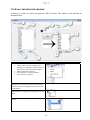
1
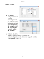
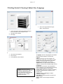
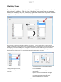
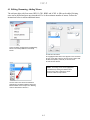
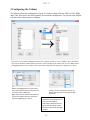
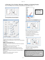
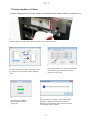
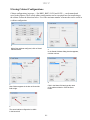
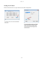
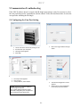
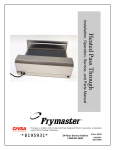
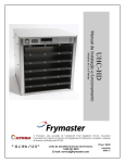
UHC-P
Mini Computer-Based Software Instructions
Frymaster, a member of the Commercial Food Equipment Service Association, recommends
using CFESA Certified Technicians.
*8196790A*
24-Hour Service Hotline 1-800-551-8633
Email: [email protected]
Price: $6.00
819-6790A
FEBRUARY 12
NOTICE
IF, DURING THE WARRANTY PERIOD, THE CUSTOMER USES A PART FOR THIS MANITOWOC
EQUIPMENT OTHER THAN AN UNMODIFIED NEW OR RECYCLED PART PURCHASED DIRECTLY
FROM FRYMASTER/DEAN, OR ANY OF ITS AUTHORIZED SERVICE CENTERS, AND/OR THE
PART BEING USED IS MODIFIED FROM ITS ORIGINAL CONFIGURATION, THIS WARRANTY WILL
BE VOID. FURTHER, FRYMASTER/DEAN AND ITS AFFILIATES WILL NOT BE LIABLE FOR ANY
CLAIMS, DAMAGES OR EXPENSES INCURRED BY THE CUSTOMER WHICH ARISE DIRECTLY
OR INDIRECTLY, IN WHOLE OR IN PART, DUE TO THE INSTALLATION OF ANY MODIFIED PART
AND/OR PART RECEIVED FROM AN UNAUTHORIZED SERVICE CENTER.
THE UHC-P IS NOT SUITABLE FOR OUTDOOR USE. WHEN OPERATING THIS UNIT, IT
MUST BE PLACED ON A HORIZONTAL SURFACE.
THE UHC-P IS NOT SUITABLE FOR INSTALLATION IN AN AREA WHERE A WATER JET CAN
BE USED. THIS APPLIANCE MUST NOT BE CLEANED WITH A WATER JET.
FOR YOUR SAFETY
DO NOT STORE OR USE GASOLINE OR OTHER FLAMMABLE VAPORS AND LIQUIDS IN
THE VICINITY OF THIS OR ANY OTHER APPLIANCE.
DO NOT OPERATE OR SERVICE THE UHC-P WITHOUT FIRST READING THIS MANUAL.
DO NOT OPERATE THE UHC-P UNLESS IT HAS BEEN PROPERLY INSTALLED AND
CHECKED.
DO NOT OPERATE THE UHC-P UNLESS ALL SERVICE AND ACCESS PANELS ARE IN
PLACE AND PROPERLY SECURED.
DO NOT ATTEMPT TO REPAIR OR REPLACE ANY COMPONENT OF THE UHC-P UNLESS
ALL POWER TO THE UNIT HAS BEEN DISCONNECTED.
USE CAUTION WHEN SETTING UP, OPERATING, OR CLEANING THE UHC-P TO AVOID
CONTACT WITH HEATED SURFACES.
UHC-P
Table of Contents
Chapter
Warranty/Software/Hardware Availability
Before You Start
Getting Started: Choosing Cabinet Size, Language
Software Interface Annotation
Building Menus
Configuring Cabinets
Entering/Editing Products
Transferring Data to the Cabinet
Saving Cabinet Configurations
Communication Troubleshooting
Page
i
1-1
2-1
3-1
4-1
5-1
6-1
7-1
8-1
9-1
Please note, the mini computer, the UHC-P software and the IR dongle are all
specially configured by Frymaster for communication with the UHC-P cabinet. The
computer and the dongle ARE NOT available from their original manufactures or
other suppliers configured for the cabinet. Replacements must be ordered from
Frymaster.
Warranty
The mini computer is warranted for 10 months from date of receipt by its
manufacturer. You must register it at upon receipt. Computer issues should be
coordinated with the computer manufacturer. Do not return the computer to
Frymaster.
The dongle is warranted for 10 months from date of receipt by Frymaster.
i
UHC-P
1 Before You Start
• All cabinet
configuration work
with the
minicomputer and
the software should
be done in the back
office. Only bring
the computer into
the kitchen when
ready to update
the cabinets.
• Cabinets should be
labeled — UHC1, UHC2 — to ensure the
menus/configurations and cabinets are properly matched
when updating UHC-P’s.
1-1
UHC-P
2 Getting Started: Choosing Cabinet Size, Language
2
1.
Click in the Login window and type admin. Click Continue. 1
1.
2.
3.
Launch the UHC‐P software by double clicking on the icon found on your computer screen. The login screen appears. Click Login 3
4
1.
2.
3.
The setup screen appears. Click on View. In the pulldown, select Cabinet. *NOTE: Serial port number is
displayed only if dongle is attached.
The number displayed with the
dongle attached is assigned by the
computer and may not match
number shown here.
2-1
1 Language: Choose a language for the software
interface and the cabinet’s menu from the
pulldown.
2 Size: Choose the size of the cabinet to be
programmed: 4-slot wide, 2- slot wide or narrow.
3 Units: Choose the temperature scale to be
displayed F for Fahrenheit, C for Celsius.
4 Serial Port:* Com port selection; handled by
software. Communication troubleshooting covered
in Chapter 9.
5 Prod Time: The amount of time the product
name is displayed on the cabinet before switching
to the remaining hold time for the product.
6 Timer Time: The amount of time the remaining
hold time is displayed before switching to the
product name.
7 Offsets: Used in calibrating the cabinet.
Covered in Chapter 8.
8: Re-Addr: A technical function covered in the
service manual.
9 Done: Used to save changes and exit the
screen.
UHC-P
3 Software Interface Introduction
A number of screens are used to navigate the UHC-P software. The features of the software are
annotated below:
Setup Screen Feature
1View: Click here to view:
• Cabinet, where cabinet is configured for
language, size, temperature range. Interface is
in this section. Also described in Chapter 2.
• Menus, described in Chapter 4.
• Saved Cabinets, covered in Chapter 8.
• Info, software version data.
Image
2 Food Library: Food items and their holding
parameters are entered and stored here. They must be
moved to a menu on the opposite side to be accessible
on the cabinet.
3 Cabinet: Used to display cabinet configured for
chosen menu or to display for reconfiguring of selected
menu.
4. Menu: Use to select menu to build in the menu
window.
3-1
UHC-P
5 Copy: 1 Highlight an item in the Food Library. 2 Click
on Copy. 3 It moves to the displayed menu.
6 Menu: View items in the menu for use on a cabinet
configuration.
7 Edit: Use to edit the holding parameters for an existing
product or to establish the parameters for a new product.
Featured covered in Chapter 6
8 Add: Click to begin the process of adding a new
product.
9 Menu: Displays existing menus and allows for the
creation of additional menus. Five is the maximum.
Feature covered in Chapter 4.
10 Remove: Click after highlighting an item in the Menu
window.
3-2
UHC-P
Cabinet Configuration Feature
1: Language
2: Size
3: Units
4: Serial port*
5: Timer Time
6: Prod Time
7: Offsets
8: Re-Addr
9: Done
Explanation
Select language for software graphics and menu.
Set size of cabinet, two, three slots or narrow.
Set temperature scale displayed, Celsius or Fahrenheit.
Establishes the computer port being used by the IR device.
The length of time, in seconds, the remaining hold time is
displayed on an active timer before displaying the product
name.
The length of time, in seconds, the product name is
displayed on an active timer before displaying the
remaining holding time.
Used to calibrate the cabinet.
Used by a technician when a board or display is changed.
Used to exit the screen.
*NOTE: Serial port number is displayed only if dongle is attached.
The number displayed with the dongle attached is assigned by the computer and may not match number shown here.
3-3
UHC-P
4 Building Menus
The cabinet has four menu configurations, which are assembled from food items created and stored
in the software’s food library. Below is a view of the cabinet’s setup screen. Items are created and
stored in the food library and moved, as necessary, to the menu column where they will be available
to populate row positions on the cabinet as it is configured.
Food items are created and stored in the Food Library (left above). Items are made available for menu-specific
cabinet configurations by placing them in menus with the desired name. Food items can be placed in multiple menus,
meaning they can be used in multiple menu configurations. Food items are not available for placement in cabinet
menu configurations in which they are not listed in the menu of the same name. For example, if 10-1 patties are not
listed in the menu for LCH2, they are not available when configuring the cabinet for LCH2.
With the desired menu chosen under the Menu pulldown, highlight the item in the Food Library to move to that menu. Click the copy key and the item appears in the menu window. Repeat to add more items. All items in the right menu column will be available for placement in the cabinet configuration of the same name. Repeat for all desired items and menus. With the pulldown under the Menu setting on the right (see arrow), choose the menu you wish to add items to. 4-1
UHC-P
4.1 Editing, Renaming, Adding Menus
The software ships with four menu: BFK1, LCH1, BFK2 and LCH2. A fifth can be added. Existing
ones can be deleted and new ones introduced. Five is the maximum number of menus. Follow the
instructions below to add an additional menu.
Access the Menu Configuration by highlighting Menu in the View pulldown on the Setup Screen. 1: Click the new button. 2. A highlighted New Menu item appears in the menu box. 3. Type a four‐digit name for the new menu in Abbr. field. 4. Add a description, if desired, of the new menu. 5. Click the Save button. NOTE: An existing menu can be highlighted and deleted by clicking the delete button. A new menu, with a new name, can be created. Follow the steps above. The new menu item will be accessible for populating in the Menu pulldown above the Menu window on the setup screen. Building menus is described in Section 4. 4-2
UHC-P
5 Configuring the Cabinet
The software allows the configuration of up to five menus. It ships with four: BFK1, LCH1, BFK2
and LCH2. Each item is selected separately for each menu configuration. The process starts with the
selection of the cabinet menu to configure.
In the Select View pulldown, highlight the menu to be configured. In the view above, BFK1 is chosen. Remember
only items in the Menu column with the same name will be available for the cabinet when it is set to BFK1. When
the highlighted Select View is double clicked, the cabinet configuration for that menu is displayed (see below).
Release the highlighted menu choice under Select View and the cabinet configuration for the chosen menu is displayed. Right click on the top left item and choose an item for that position from the drop‐down menu by highlighting your choice. Continue for each row position until all the desired cabinet positions are populated with food items. NOTE: The left most item establishes the temperature for a row. Items with holding temperatures different than the item in the left position cannot be placed in the middle and right positions. 5-1
UHC-P
6 Entering a New Product, Deleting or Editing an Existing Product
Items can be added to the Food Library and then moved to the relevant menus.
NOTE: New items must have a holding temperature shared by other products. 1
In the setup window, click on the Add button (see arrow) below the Food Library window. 2
Scroll to find the item named New Item in the Food Library and click on it, which highlights the item. Click the Edit button. 4
To move a newly added item to a menu for use in the cabinet follow these instructions: 1: In the Setup view, choose the menu you want the new item to appear in. 2: Highlight the new item in the Food Library. 3: Click on the Copy button. 3
In the Edit Food Item window, enter the following details: 1 ABBR: A four‐letter abbreviation for the item, which will be displayed on the cabinet. 2 Delete: Click here to delete item. 3 Descr: A short description of the item. 4 Temp Top: The top plate temperature (the temperature the product will be held). 5 Temp Bott: Bottom plate temperature (same as top). 6 Time: Holding time for product (in minutes). 7 Cook More: Time when the Cook More display will be shown. 8 Yellow: Time when Yellow light will be displayed, indicating little holding time is left. 9 Red: Time when Red light will be displayed, indicating holding time is nearly expired. 10 Cancel: Cancels operation without saving data. 1
11 OK: Click to save entered data. 1
6-1
5
The new item (see arrow) is available for placement in a cabinet configuration and transfer to the cabinet. Change or Delete Items Change: Existing items can be edited in the same manner. Highlight the item to be edited and start at step 2. Adjust the necessary parameters in step 3 and click OK. Delete: Start at step 2; highlight item to delete and click delete in step 3. Click OK. UHC-P
7 Transferring Data to Cabinet
Cabinet configurations built in the software are transferred to the cabinet with the external IR device.
1
Hold the IR device in front of the cabinet lens (dark circle at right on the front).
3
2
In the chosen cabinet view, hit the transfer button
with the IR device positioned in front of the
cabinet’s lens. See above.
From the setup screen, navigate to the cabinet view
by selecting a cabinet from the Cabinet pulldown
menu.
4
5
The computer will display a
transfer dialog box with a
progress bar.
When the transfer is complete, a Successful Transfer
dialog box is displayed. Click OK. The cabinet’s
Breakfast, Lunch and other menus will now match the
cabinet displays on the software.
7-1
UHC-P
8 Saving Cabinet Configurations
Cabinet configurations, in groups — like BKF1, BKF2, LCH1 and LCH2 — can be named and
saved in the software. These saved cabinet configurations can be reacquired later for transferring to
the cabinet. Follow the directions below. Five is the maximum number of menus that can be saved in
a cabinet configuration.
1
With all the cabinets configured, click on Saved
Cabinets button.
2
In the Saved Cabinets dialog box that appears,
click the new box.
4
3
Click in the Name field and type the name
of the cabinet collection. Click the Save
button.
New Cabinet appears in the box at left and the
field at right.
5
The saved cabinet configuration is visible
in the box at left.
8-1
UHC-P
Loading Saved Cabinets
Follow the directions below to acquire and load saved cabinet configurations.
1
In a cabinet view, click on the Saved Cabinet
radio button.
2
In the Saved Cabinet dialog box, highlight
the desired cabinet and click Open. The
cabinet configurations for BFK1, BKK2,
LCH1 and LCH2 will be changed to the
selected cabinet.
8-2
UHC-P
9 Communication Troubleshooting
If the UHC-P software doesn’t recognize the IR dongle upon startup, it may be necessary to select
the com port being used to communicate with the cabinet. Follow the directions below to select the
com port after attaching the IR dongle.
9.1 Configuring the Com Port Setting
2
1
1.
2.
3.
4.
Launch the UHC‐P software by clicking on the icon found on your computer. The login screen appears. Click Login 1.
Click in the Login window and type admin. 1.
The Cabinet Configuration screen appears. Choose the Com Port established in the setup of the IR software. 3
1.
2.
3.
The setup screen appears. Click on View. In the pulldown, select Cabinet. 4
2.
*NOTE: Serial port number is displayed
only if dongle is attached.
The number displayed with the dongle
attached is assigned by the computer and
may not match number shown here.
9-1
Shipping Address: 8700 Line Avenue, Shreveport, Louisiana 71106
TEL 1-318-865-1711
FAX (Parts) 1-318-219-7140
PRINTED IN THE UNITED STATES
FAX (Tech Support) 1-318-219-7135
SERVICE HOTLINE
1-800-551-8633
Price: $6.00
819-6790A
FEB 12