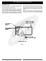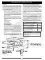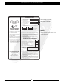
1
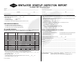
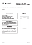
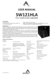
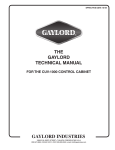
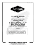
EFFECTIVE DATE 4-05
THE
GAYLORD VENTILATOR
TECHNICAL MANUAL
FOR THE GRAND “GX2” SERIES
NON WATER-WASH VENTILATORS
GAYLORD INDUSTRIES
10900 S.W. AVERY STREET • TUALATIN, OREGON 97062-1149 U.S.A.
800-547-9696 • 503-691-2010 • FAX: 503-692-6048 • email: [email protected]
GAYLORD INDUSTRIES, INC.
“Undisputed World Leader in
Engineered Systems for
Commercial Kitchens”tm
World Headquarters: 10900 S.W. Averry Street • Tualatin, Oregon 97062-1149 U.S.A.
To Our Customers. . .
Congratulations on your recent purchase of a Gaylord
kitchen exhaust hood system. We are proud to be able
to provide you with a quality product that incorporates
the latest engineering concepts and is a result of over
50 years of experience in the foodservice kitchen
exhaust industry.
If you have other Gaylord equipment such as a Gaylord
Utility Distribution System, Quencher Fire Protection System, or Roof Top Air Handling Equipment, etc., please
refer to the corresponding supplementary equipment
manuals.
If you have further questions, please call us toll free at
1-800-547-9696 or email:[email protected]. We are
more than happy to help.
Sincerely,
Gaylord Industries
STREET ADDRESS: 10900 S.W. Avery Street, Tualatin, Oregon 97062-8549 U.S.A.
PHONE: 503-691-2010 • 800-547-9696 • FAX: 503-692-6048 • email: [email protected] • www.gaylordusa.com
COMMERCIAL KITCHEN EXHAUST SYSTEMS • FIRE PROTECTION • UTILITY DISTRIBUTION • ROOF TOP UNITS • POLLUTION CONTROL
TABLE OF CONTENTS
“GX2” SERIES PRINCIPLE OF OPERATION ........................................................ 3
STANDARD MODELS ............................................................................................ 6
MAINTENANCE AND CLEANING INSTRUCTIONS.............................................. 7
TROUBLESHOOTING ........................................................................................... 8
MEASURING INLET SLOT VELOCITY ................................................................. 10
WIRING DIAGRAMS .............................................................................................. 13
PARTS LIST ........................................................................................................... 17
START-UP INSPECTION REPORT ....................................................................... 20
WARRANTY ................................................................................. Inside back cover
PATENT NUMBERS
U.S.A.:
4,266,529
4,281,635
4,356,870
CANADA:
1,139,151
1,155,366
GERMANY: 8,034,240
ALL RIGHTS RESERVED. NO PART OF THIS BOOK MAY BE REPRODUCED, STORED
IN A RETRIEVAL SYSTEM, OR TRANSMITTED IN ANY FORM BY AN ELECTRIC, MECHANICAL, PHOTOCOPYING, RECORDING MEANS OR OTHERWISE WITHOUT PRIOR
WRITTEN PERMISSION OF GAYLORD INDUSTRIES, INC. COPYRIGHT 2003.
© Copyright 2005, Gaylord Industries
The manufacturer reserves the right to modify the materials and
specifications resulting from a continuing program of product improvement or the availability of new materials.
ADDITIONAL COPIES $10.00
“GX2” SERIES PRINCIPLE OF OPERATION
The Gaylord “GX2” Series Non Water-Wash Ventilator
offers simplicity, economy and performance that no other
ventilator can offer. The unique “extractor insert” gives a
grease extraction efficiency far superior to that of a typical
baffle filter. The Gaylord “GX2” Series Ventilators are UL
Listed and meet all the requirements of NFPA #96 and the
International Mechanical Code.
through it. Grease extraction is accomplished by unique,
removable stainless steel “extractor inserts” which incorporates a series of horizontal baffles. As the air moves
through the extractor at high speed, it is forced to make a
series of turns around these baffles, forcing the heavierthan-air particles of grease, dust, and lint to be thrown out
of the airstream by centrifugal force. The sticky grease
collects in the extractor and the liquified grease drains
down into the main grease gutter which slopes to the
grease cup. Note: Some ventilators may be equipped with
optional “Custom Air” baffles (shown dotted) to reduce the
exhaust volume over specific light duty cooking appliances. The extractor inserts come in two sizes15½" (5.6
lbs.) and 19½" (6.75 lbs.). IMPORTANT NOTE: Never
operate ventilator without extractor inserts in place.
EXHAUST FAN OPERATION
The exhaust fan is controlled by the Gaylord C-150
“Exhaust Fan Start/Stop Switch”, an optional switch, or a
standard wall switch. The switch is usually located on a
wall near the ventilator. When the switch is flipped up to the
on position, the damper begins opening to the exhaust
position (refer to Fig. 1). After the damper opens (approximately 80 seconds) the exhaust fan will come on.
GREASE EXTRACTION
The Gaylord “GX2” Series Ventilator extracts 90% of the
grease, dust, and lint particles from the airstream passing
FIG. 1
3
“GX2” SERIES PRINCIPLE OF OPERATION
CLEANING
At the end of the cooking day the exhaust fan is turned off
by the “Exhaust Fan Start/ Stop Switch.” In addition to the
fan going off, the two position damper moves to the fan off
position (See Fig 2.). This prevents conditioned air from
going up the exhaust system during off hours. After the fan
has been turned off, the extractor inserts are removed and
can be washed either in a dishwasher or soaked and
rinsed off. The grease cup is also removed and emptied at
this time. To ease in the removal of the extractor inserts,
an “Extractor Removal Tool” is available which eliminates
the need for kitchen personnel to climb up on the cooking
equipment, or up a ladder.
FIG. 2
4
“GX2” SERIES PRINCIPLE OF OPERATION
FIRE PROTECTION
the ductwork and spreading to other parts of the building. The
fire is contained in the kitchen area where it can be properly
fought. After the thermostat cools below 250°F, the damper
automatically opens to the exhaust position and the fan
re-starts.
NFPA #96 requires the use of surface, duct and plenum
protection on all hoods. It is these systems that are the first
line of defense against equipment fires.
The “GX2” Series ventilator incorporates a two position
damper, a fail safe damper control and a fail safe thermostat.
In the event of a fire, should the thermostat located at the duct
collar reach 250°F, the damper control is de-energized
closing the damper to the fire position (See Fig. 3) and the
exhaust fan shuts off. This prevents the flames from entering
Surface, duct collar and plenum fire protection utilizing The
Gaylord Quencher System or other fire protection systems
currently on the market can be factory installed as an option.
FIG. 3
5
STANDARD VENTILATOR MODELS
Model GX2-BDL
Model GX2-BDL-CL
Application - Wall mounted canopy
style for all types of equipment.
Application - For single island
arrangements
Model GX2-BDL-DS
Model GX2-BDL-BB
Application - For island style
cooking arrangements where one side
of the cooking line is light duty equipment
and the other side medium duty equipment.
Application - For island style
cooking arrangements over all duties
of equipment.
STANDARD MAKE-UP AIR OPTIONS
The make-up air options shown below are available on all BDL Series Ventilators
except the MAI Series is not available on the GX2-BDL-CL.
MODEL “MAW” SERIES
MODEL “MAI” SERIES
FRONT FACE DISCHARGE
INTERNAL DISCHARGE
This method of introducing make-up air into the
kitchen is flexible and has many advantages.
Make-up air is discharged through stainless steel
perforated panels as illustrated (MAW Series) or
optional registers (MAR Series). Typical supply
volume is 80% of the exhaust or more, depending on air balance desired. Supply air temperatures should range from 60 to 65°F (16 to 18°C),
but may be as low as 50°F (10°C) depending on
air volume, distribution, and internal heat load.
This method of introducing air into the hood is
typically referred to as the “short circuit” method.
This design has very limited applications and the
amount of supply air able to be introduced varies
considerably with the type of cooking equipment.
This air may be untempered air in most areas
depending upon climatic conditions and the type
of cooking equipment. The difference between
the quantity of air being introduced and the
amount of air being exhausted must be supplied
through a traditional make-up air system.
6
MAINTENANCE AND CLEANING INSTRUCTIONS
CLEANING
At the end of each cooking day, the exposed interior
surfaces of the ventilator should be wiped down and the
grease cup emptied. During the course of operation, grease
particles are gradually collecting inside the extractor inserts.
Daily, or at periodic intervals, depending on the type of cooking, the extractor inserts must be removed and cleaned.
To clean, proceed as follows:
1.Remove extractor inserts by hand or by using the
extractor removal tool. CAUTION: Care should be
taken when removing extractors, especially over fryers. It is recommended that the cooking equipment be
cooled down and the fryers be covered prior to removing
extractors. To remove, lift up slightly on extractor insert
and pull straight out.
2.Extractor inserts may be cleaned either by using a dishwasher or by washing in a sink using hot water and a
degreasing detergent. Formula G-510 is highly
recommended for this application. For information
contact:
20/10 Products Inc.
P.O. Box 7609
Salem, OR 97303
Phone: 800-286-2010
Fax: 503-363-4296
E-mail: [email protected]
3.With the extractor inserts removed, wipe and clean the
back wall and the grease gutter with hot detergent water. NOTE: If a steam or hot water pressure washer is
used for periodic cleaning of the interior, connect a hose
to the gutter drain and lead it to a floor sink or large
bucket to drain off the water.
4.To replace the extractor inserts, care must be taken to
insure that point “A” rests in the rear clip as illustrated
in Fig. 4.
5.If the ventilator(s) has a fuse link operated supply duct
fire damper NFPA-96 requires inspection of the fuse
link every 6 months and replacement annually.
INSPECTION AND CLEANING REQUIREMENTS
The 2001 edition of NFPA-96 (Standard for Ventilation Control and Fire Protection of Commercial Cooking Operations)
require that hoods, ducts and exhaust fans be inspected
by a properly trained, qualified and certified company or
person(s) in accordance with the following table.
Upon inspection, if found to be contaminated with deposits
from grease- laden vapors, the entire exhaust system shall
be cleaned by a properly trained, qualified, and certified
company or person(s) acceptable to the authority having
jurisdiction.
When a vent cleaning service is used, a certificate showing date of inspection or cleaning shall be maintained on
the premises. After cleaning is completed, the vent
cleaning contractor shall place or display within the kitchen
area a label indicating the date cleaned and the name of
the servicing company. It shall also indicate areas not
cleaned. Factory trained service agencies are certified by
Gaylord Industries, Inc. to perform these inspections. For
the name and phone number of your nearest agent call
800-547-9696 or www.gaylordusa.com and go to service.
EXHAUST SYSTEM INSPECTION SCHEDULE
Systems serving solid fuel cooking operations
Monthly
Systems serving high-volume cooking operations such as
24-hour cooking, charbroiling or wok cooking
Quarterly
Systems serving moderate-volume cooking operations
Semiannually
Systems serving low-volume cooking operations, such as
churches, day camps, seasonal businesses, or senior
centers
Annually
CAUTION: Care should be taken when removing extractors,
especially over fryers. It is recommended that the cooking
equipment be cooled down and the fryers be covered prior to
removing extractors.
FIG. 4
7
TROUBLE-SHOOTING
SYMPTOM
SMOKE LOSS
1. Smoke Loss- Ventilator is not
exhausting properly.
POSSIBLE PROBLEM
CORRECTIVE ACTION
A. L o w a i r v e l o c i t y - Av e r a g e a i r v e l o c i t y
through the air entr y slot should be in
accordance with the Air Velocity Char t on
page 10. For proper method of measuring
t h e a i r ve l o c i t y, r e fe r t o p a g e 1 1 . I f t h e
velocity is low check the following.
1. Broken or slipping belt on the exhaust fan.
2. Proper rotation of the exhaust fan wheel.
3. P r o p e r s i z e o f e x h a u s t f a n ( f a n m u s t
deliver nameplate rating).
4. Ductwork inspection panel left open.
5. Damper not open or in proper position.
B. The Gaylord Ventilator must have its own
ex h a u s t s y s t e m a n d n o o t h e r ex h a u s t ,
such as dishwasher hoods, should be tied
into it.
1. Inspect duct system and verify that there
are no type II ventilator systems tied in. If
so they must be removed.
C. Improperly placed make-up air diffusers.
1. Make-up air directed at the ventilator will
likely create cross drafts disrupting the air
flow into the ventilator. Adjust the louvers
to direct the make-up air away from the
ventilator.
2. Make-up air should be delivered through
full length perforated diffusers or registers
at ceiling height distributed throughout the
kitchen area.
3. M a k e - u p a i r r e g i s t e r s l o c a t e d n e a r t h e
ventilator, the louvers should be adjusted
to direct the air away from the ventilator.
D i r e c t i n g o r fo r c i n g m a k e - u p a i r a t t h e
ve n t i l a t o r t y p i c a l l y c r e a t e s c r o s s d r a f t s
resulting in smoke loss.
D. Inadequate make-up air.
1. M a k e - u p a i r m u s t b e s u p p l i e d f o r
replacement of air exhausted through all
kitchen exhaust systems.
2. A general "rule of thumb" is that 75% to
80% of the replacement air should be
fresh, conditioned, (heated or cooled) air
brought into the kitchen area, with the
remaining 20% to 25% allowed to flow into
the kitchen from adjacent areas.
E. Exhaust fan discharge.
1. T h e r e s h o u l d b e n o s c r e e n o v e r t h e
d i s c h a r g e . I f o n e i s fo u n d , i t s h o u l d b e
removed.
2. The direction of discharge should not be
into the prevailing winds nor downward
onto the roof. A ver tical discharge is highly
recommended.
GREASE EXTRACTION
1. Poor Grease Extraction.
A. T h e G a y l o r d " G X 2 " S e r i e s Ve n t i l a t o r
extracts up to 90% of the grease, dust and
lint par ticles from the airstream passing
through it, when operated and maintained
in accordance with design specifications.
I f i t a p p e a r s t h a t t h e ve n t i l a t o r i s n o t
extracting properly, typically the exhaust
volume is low.
8
1. Check the inlet slot velocity as described
on pages 10 through 12. If the velocity is
not within the required range, increase or
reduce the fan speed as required.
TROUBLE-SHOOTING
SYMPTOM
EXHAUST FAN
POSSIBLE PROBLEM
CORRECTIVE ACTION
1. The fan switch is turned on but damper
does not move to the open position and
exhaust fan does not star t but you can
hear the fan running.
A. Fan on/off switch has not been wired
through the ventilator.
1. R e f e r t o w i r i n g d i a g r a m i n t h i s
manual and re-wire.
2. If when the fan switch is turned on the
damper moves to the exhaust postion
but the exhaust fan does not come on.
A. Overload protector on magnetic star ter
tripped.
1. P u s h t h e " R e s e t " b u t t o n o n t h e
magnetic star ter and the push the
"Star t Fan" button on the command
center.
B. If an HOA (Hands On/Automatic) type
m a g n e t i c s t a r t e r sw i t c h i s u s e d , t h e
selector switch may have been moved
from the automatic position
1. Check switch and turn selector to the
automatic position.
C. Exhaust fan circuit breaker tripped.
1. Re-set circuit breaker
D. I f t h e s y s t e m i s e q u i p p e d w i t h a n
disconnect switch for the exhaust fan, a
fuse or fuses may have blown out.
1. C h e c k c o n t i n u i t y o f f u s e s a n d
replace if necessar y.
E. Fan on/off switch has not been wired
properly through the ventilator.
1. R e f e r t o w i r i n g d i a g r a m i n t h i s
manual and re-wire.
9
MEASURING INLET SLOT VELOCITY
MEASURING INLET SLOT VELOCITY
Smoke capture and grease extraction efficiency are dependent upon the proper air velocity at the inlet slot of the
ventilator.The required average slot velocities are shown
on the “Air Velocity Chart” below. If the slot velocity is
below the required average, the exhaust fan must be adjusted accordingly.
NOTE: The height of the inlet slot can vary depending
upon the design of the ventilator. It is, therefore, important to first measure the inlet slot and compare it to the
chart below to determine the required average inlet slot
velocity. The designed CFM per lineal foot is related to
the velocity as shown on the chart below. The total CFM
for the ventilator can be found on the ventilator nameplate. (See Figure 6).
AIR VELOCITY CHART
FOR ALL "GX2" SERIES EXCEPT "DS" SERIES
Without Custom
Air Baffles
Nominal
Height
Designed
of
Inlet Slot CFM per
Lineal Ft.
With Custom
Air Baffles
Average Inlet
Slot Velocity (FPM)
Designed
CFM per
Lineal Ft.
Min. Optimum Max.
3"
4"
Average Inlet
Slot Velocity (FPM)
Min. Optimum Max.
250
1300
1380
1450
150
760
800
880
270
1360
1435
1500
160
790
830
870
285
1425
1500
1575
170
810
855
900
300
1465
1545
1625
180
845
880
935
400
1690
1780
1870
250
1040
1095
1150
FOR "DS" SERIES VENTILATORS*
Designed CFM Per
Lineal Ft.
Required Average Inlet
Slot Velocity (FPM)
Total
Both
Slots
Front
Slot
Rear
Slot
300
150
150
760
800
880
595
625
655
400
250
150
1375
1450
1520
595
625
655
Front Slot
Rear Slot
Min. Optimum Max. Min. Optimum Max.
Air velocity readings less than what is specified on the
“Air Velocity Chart” may allow smoke and grease to escape the confines of the ventilator and/or reduce grease
extraction efficiency. This can result in grease deposits
which lead to sanitation problems or fire hazards if left
uncorrected. If air velocity readings are higher than those
specified, it will require more energy to operate the exhaust fan and excessive noise levels will result. Higher
or lower velocities than the required average will normally
put the entire heating and ventilating system out of balance. When measuring the air velocity it is very important
to take an average reading across the inlet slot plane as
described on Page 11. Positioning the sensing head incorrectly will give velocity readings that cannot be compared to the “Air Velocity Chart”.
10
MEASURING INLET SLOT VELOCITY
The standard instrument used for measuring the inlet velocities on a
Gaylord Ventilator is a Pacer, Model DA40 or DA4000 Digital Anemometer.
This instrument is the easiest, most accurate and the best suited for
measuring ventilator inlet slot velocities. To take accurate air velocity
readings, follow the instructions below.
Instructions
FIG. 5A
FIG. 5B
1. It is first necessary to determine if the ventilator includes Custom Air
baffles as shown in Fig. 5B. If shop drawings are available, and if equipped,
the custom baffles and their location will be noted on the front elevation. If
not available, to determine if Custom Air baffles are provided run your hand
along the bottom inlet slot and feel for the Custom Air baffle as illustrated
in Fig. 5B.
2. If the ventilator includes Custom Air baffles, it will be necessary to take
two sets of readings - one for the section of ventilator that includes Custom
Air baffles and one where it does not.
3. Attached the sensing head guide bracket, Gaylord Part Number 18408,
to the sensing head.
4. Attach the cable from the sensing head to the meter and the handle
sections to the sensing head.
5. Place the sensing head guide bracket against the lower lip of the inlet slot
as illustrated.
6. Using the 16 second averaging feature on the meter, slide the sensing
head along the slot, back and forth, for a 3'-0" to 4'-0" distance, and record
the velocity at the end of the 16 second mark. Continue this process for the
full length of the ventilator.
Important Note: If the ventilator includes custom air baffles as illustrated
in Fig. 5B, always take separate readings on the section of the ventilator that
includes custom air from the section that does not have the baffles. Non
custom air and custom air readings must be recorded separately. Do not
average them together.
Important Note: On the rear slot of a Model BDL-DS Series, do not use the
guide bracket. Refer to Figure 5C.
7. Record the velocity (fpm) on the start up inspection report form. A sample
report form, which can be photocopied, is provided on page 16.
8. The designed, or optimum velocity, is noted on the shop drawings and
the Air Velocity Chart on page 10. Two velocities will be noted if the
ventilator includes custom air baffles.
9. Compare the recorded air velocity to the designed air velocity shown on
the shop drawings or the Air Velocity Chart on page 10. The recorded
velocity may be slightly lower or higher providing that it is within the minimum
and maximum range as shown on the Air Velocity Chart .
If the air velocity is outside the minimum/maximum range, the performance
of the ventilator will be affected and therefore the exhaust fan must be
adjusted.
FIG. 5C
CROSS SECTION OF TYPICAL
VENTILATOR INLET SLOTS
11
MEASURING INLET SLOT VELOCITY
ENGINEERING DATA
LISTED
370Y
EXHAUST HOOD WITH
EXHAUST DAMPER
THIS EXHAUST HOOD HAS BEEN TESTED
TO STANDARD UL 710 "EXHAUST HOODS
FOR COMMERCIAL COOKING
EQUIPMENT"
THIS EXHAUST HOOD IS LISTED UNDER UL
FILE NUMBER MH11403
THIS EXHAUST HOOD MEETS ALL REQUIREMENTS OF THE LATEST EDITION OF NFPA96 AND THE IMC (INTERNATIONAL MECHANICAL CODE)
o
1. MINIMUM TOTAL EXHAUST
VOLUME FOR THIS HOOD SECTION
C.F.M.
2. MAXIMUM TOTAL SUPPLY
VOLUME FOR THIS HOOD SECTION
C.F.M.
3. EXHAUST STATIC PRESSURE AT
DUCT COLLAR
W.G.
4. SUPPLY STATIC PRESSURE AT
DUCT COLLAR
W.G.
°F
FOR
LINEAL FT. OF HOOD
°F
FOR
LINEAL FT. OF HOOD
6. REFER TO GAYLORD VENTILATOR TECHNICAL MANUAL FOR INLET
VELOCITY REQUIREMENTS AND METHOD OF CHECKING VELOCITY
8. ON "GX2" and "PG" SERIES VENTILATORS EQUIPPED WITH FUSE LINK
OPERATED EXHAUST FIRE DAMPER USE ONLY 280° F , RATED 30 LBS. MIN. UL
LISTED FUSIBLE LINK FOR REPLACEMENT
9. IF HOOD IS EQUIPPED WITH INTEGRAL MAKE-UP AIR WITH FUSE LINK OPERATED FIRE DAMPER USE ONLY 165° F, RATED 30 LBS. MIN. UL LISTED FUSIBLE
LINKS FOR REPLACEMENT
10.DUCTWORK AND EXHAUST FAN
A. STATIC PRESSURE OF DUCT SYSTEM MUST BE ADDED TO VENTILATOR
STATIC FOR TOTAL SYSTEM STATIC
B. ALL DUCTWORK MUST BE WELDED LIQUIDTIGHT
MINIMUM DISTANCE FROM COOKING SURFACE TO FRONT
LOWER EDGE OF HOOD
MAXIMUM DISTANCE FROM COOKING SURFACE TO FRONT
LOWER EDGE OF HOOD
MINIMUM OVERHANG FROM FRONT OF HOOD CAVITY TO
FRONT OF COOKING SURFACE
MINIMUM OVERHANG FROM SIDE OF HOOD TO EDGE OF
COOKING SURFACE
WORLD HEADQUARTERS
GAYLORD INDUSTRIES, INC.
10900 S.W. AVERY STREET
TUALATIN, OR 97062-8549 USA
PHONE: 1-503-691-2010
FAX: 1-503-692-6048
EMAIL: [email protected]
UL-GX2/PG 1000
FIGURE 6
7. ELECTRICAL RATING OF LIGHT FIXTURES: 120 VOLT, 60 HZ. OR 220 VOLT,
50 HZ. OVERALL RATING - 12 AMPS OR LESS
MAXIMUM SETBACK FROM FRONT OF HOOD CAVITY TO
FRONT OF COOKING SURFACE
PATENT PENDING
TOTAL SUPPLY CFM HERE
5. THIS HOOD SECTION SUITABLE FOR APPLIANCES WITH MAXIMUM COOKING
SURFACE TEMPERATURE OF:
HOOD MOUNTING REQUIREMENTS
SUPPLIED WITH FACTORY INSTALLED UL LISTED
GRINNELL CORP. EA-1, 1/4" ORIFICE, 65 DEGREE
DEFLECTOR SPRINKLER(S) FOR THE PROTECTION OF UNLIMITED LENGTH OF GREASE DUCT
HAVING A MAXIMUM DUCT PERIMETER OF 50
INCHES PER SPRINKLER. CONNECT TO NFPA 13
SPRINKLER SYSTEM WATER SUPPLY ONLY.
TOTAL EXHAUST CFM HERE
SERIAL NO:
MODEL NO:
MAINTENANCE INSTRUCTIONS
1. REMOVE, INSPECT AND CLEAN FILTERS OR GAYLORD EXTRACTOR
CARTRIDGES AS REQUIRED
2. REMOVE AND EMPTY GREASE CUP AS REQUIRED
3. CAUTION - DO NOT OPERATE VENTILATOR WITHOUT FILTERS OR EXTRACTOR
CARTRIDGES IN PLACE
4. REPLACE FILTERS IN "PG" SERIES ONLY WITH UL CLASSIFIED GREASE FILTERS.
IN "PGX" AND "GX2" SERIES REPLACE WITH GAYLORD INDUSTRIES
EXTRACTOR CARTRIDGES.
5. IF THE VENTILATOR(S) HAS A FUSE LINK OPERATED EXHAUST OR SUPPLY
DUCT FIRE DAMPER THE NATIONAL FIRE PROTECTION ASSOCIATION'S
PAMPHLET NFPA-96 REQUIRES INSPECTION OF THE FUSE LINK EVERY 6
MONTHS AND REPLACED ANNUALLY. REFER TO THE GAYLORD VENTILATOR
TECHNICAL MANUAL FOR DETAILS.
12
The total required exhaust volume can be
found stamped on the UL nameplate located
on each hood section.
WIRING DIAGRAM
13
WIRING DIAGRAM
GX2 Wiring With Electric Damper
(Multi-Section First or Intermediate)
14
WIRING DIAGRAM
GX2 Wiring With Electric Damper
(Single Section or Last Section)
15
WIRING DIAGRAM
16
PARTS LIST
GAYLORD
PART NO.
DESCRIPTION
ILLUSTRATION
18380
18385
15-1/2" Extractor Inser t
19-1/2" Extractor Inser t
(250 CFM/Lin. Ft. Extractors)
18745
18746
15-1/2" Extractor Inser t
19-1/2" Extractor Inser t
(400 CFM/Lin. Ft. Extractors)
10321
165°F Fuse Link for Supply Ducts
18806
18466
Exhaust Duct Thermostat (N.C.)
6" Length 250°F. (For 250 Extractor)
15" Length 250°F. (For 400 Extractror)
18400
Extractor Removal Tool
(For 250+ 400 CFM/Lin.Ft. Extractors)
10119
Light Globe - Clear
13211
Incandescent Light Lens & Frame
12" x 12" Recessed Light Lens & Retainer
13210
10111
10112
Fluorescent Light Lens & Frame
2 Ft. Recessed Light Lens & Retainer
3 Ft. Recessed Light Lens & Retainer
4 Ft. Recessed Light Lens & Retainer
13075
Grease Cup 3-1/4" x 6" x 4"
18314
C-150 Star t/Stop Switch Control
17
DAMPER CONTROL
MODEL C-99 SERIES
PC.
NO.
1.
DESCRIPTION
Damper Control With Linkage (120 Volt) ----------------------------------
18
GAYLORD
PART NO.
18451
VENTILATOR
START-UP INSPECTION REPORT
For Model “GX2” Series Ventilators
Job Name ______________________________________________________________________________
Gaylord Representative ____________________________________________________________
Address ________________________________________________________________________________
Representative Company Name ______________________________________________________
______________________________________________________________________________________
City/State
Zip
File Number _______________________________________________ Date _________________
Facility Contact Name _________________________________________ Phone # ____________________
CSA Contacted __________________________________________________________________
MAKE-UP AIR
3. If the “GX2” Series ventilator(s) is interconnected with any “CG3” water wash series, perform the following
test:
A. With the exhaust fan on, open the electrical compartment on the control cabinet and push the “FIRE
TEST” button. The following should occur:
1. Exhaust fan shut off ___Yes ___No
2. Damper fully closed ___Yes ___No
B. At conclusion of the test push the “CANCEL” button. The following should occur:
1. The damper stayed closed ___Yes ___No
2. Fan stayed off ___Yes ___No
C. Push the “START FAN” button. The following should occur:
1. Damper moves to the fully open position ___Yes ___No
1. Kitchen make-up air supply is turned on______Yes______No
2. Type of make-up air
¨ Ceiling Registers
¨ Built into Hood
¨ Ceiling Linear Diffusers
¨ Other
3. If ceiling register or linear diffusers approximate distance from face of hood
_____________________________________________________________
FIRE DAMPER INFORMATION
¨ Ventilator has electric fire damper (GX2 Series)
¨ Ventilator has fuse link fire damper (GX2-FLD Series)
¨ Ventilator does not have a fire damper (GX2-ND Series)
2. Exhaust fan comes on ___Yes ___No
AIR VOLUME READINGS
Push “Start Fan” and take velocities. Record as follows: Exhaust record in the “EX” row, Exhaust at Custom
Air baffles (if applicable) record in the “CA” row, and Make-up Air record in the “MA” row.
ITEM NO.
AIR VELOCITIES (FPM) FROM LEFT TO RIGHT
HOOD SLOT OR MAKE-UP AIR DISCHARGE
HOOD SERIAL NO.
AVERAGE
INSTALLATION INCLUDES THE FOLLOWING:
¨ Gaylord Rooftop Unit (GRT)
¨ Gaylord Clearair Pollution Control Unit (RSPC)
¨ The Gaylord “Quencher” Fire Protection System
¨ Gaylord Distributor (UDS)
¨ Wet Chemical Fire Protection System
EX
CA
Personnel provided with ventilator technical manual________Yes________No
MA
Inspection Witnessed By (Print Name) ______________________________________________________
Signature ________________________________________________ Date _______________________
EX
CA
MA
Comments ____________________________________________________________________________
____________________________________________________________________________________
____________________________________________________________________________________
EX
____________________________________________________________________________________
CA
MA
ELECTRIC DAMPER TEST (If equipped):
1. Remove one or more extractors so damper is visible. Push the “START FAN” button.
A. The damper should move to the fully opened position in approx. 1 minute 15 seconds. _____Yes ___No
B. The exhaust fan came on ___Yes ___No
2. Push “STOP FAN” button.
A. The damper should move to the fully closed position in approx. 15 seconds_____Yes_____No
B. The exhaust fan shut off ___Yes ___No
Form No. GX2SUR200
____________________________________________________________________________________
__________________________________________________________________________________________________
__________________________________________________________________________________________________
Distribution: WHITE-Gaylord Industries, Inc. YELLOW-Customer PINK-Dealer
GOLDENROD-Sales Rep Litho U.S.A.
GAYLORD INDUSTRIES
10900 S.W. Avery Street • Tualatin, OR 97062-1149
PHONE:1-503-691-2010 • FAX: 1-503-692-6048 • email:[email protected]
LIMITED WARRANTY
THE GAYLORD NON WATER-WASH VENTILATOR
LIMITED WARRANTY
August 2000
The Gaylord Ventilator and component parts furnished with The Gaylord Ventilator by the
Licensed Gaylord Manufacturer are warrantied by the Licensed Gaylord Manufacturer
producing the ventilator to be free from defects of material and workmanship under normal
use when installed, operated and serviced in accordance with factory recommendations.
The Licensed Gaylord Manufacturer's obligation under this warranty and any warranties
implied by law shall be limited to repairing or replacing at its option any part of said
equipment when the Licensed Gaylord Manufacturer's examination shall disclose to its
satisfaction to be thus defective, for a period of one (1) year from the date of beneficial use,
or eighteen months from date of shipment, whichever occurs first, provided proper and
acceptable evidence of such is recorded at the factory. THE LICENSED GAYLORD MANUFACTURER SHALL NOT BE RESPONSIBLE FOR INCIDENTAL OR CONSEQUENTIAL
DAMAGES RESULTING FROM A BREACH OF THIS WARRANTY.
In the United States the labor required to make repairs and replacements under this warranty shall be furnished by Gaylord Industries Inc. or the Licensed Gaylord Manufacturer or
its authorized representative. Such labor shall only be provided Mondays through Fridays
between the hours of 8 a.m. and 4 p.m. Requests for repairs or replacement parts should
be made to GAYLORD INDUSTRIES INC., P.O. Box 1149, Tualatin, Oregon 97062-1149.
Outside the United States, all replacement parts furnished under this warranty shall be
F.O.B. Gaylord Industries, Inc., Tualatin, Oregon U.S.A. The owner shall pay the necessary freight delivery charges, and the necessary labor for removal and installation of parts,
and any tariffs, duties or taxes.
This warranty does not cover routine maintenance or malfunctions or improper operation
caused by fluctuating electrical power or power surges, and improper exhaust fan operation.
This is the sole warranty with respect to the aforesaid items. NEITHER THE GAYLORD
LICENSEE NOR ANY OTHER PARTY MAKES ANY OTHER WARRANTY OF ANY KIND
WHATSOEVER, EXPRESSED OR IMPLIED, AND ALL IMPLIED WARRANTIES OF
MERCHANTABILITY AND FITNESS FOR A PARTICULAR PURPOSE WHICH EXCEED
THE AFORESAID OBLIGATIONS ARE HEREBY DISCLAIMED AND EXCLUDED FROM
THIS AGREEMENT.
WORLDWIDE SALES, MANUFACTURING AND SERVICE
FOR THE NAME AND LOCATION OF THE NEAREST
CERTIFIED SERVICE AGENCY, VISIT OUR WEB SITE:
WWW.GAYLORDUSA.COM
OR CONTACT US AT:
GAYLORD INDUSTRIES
10900 S.W. AVERY STREET
TUALATIN, OREGON 97062-1149 U.S.A
Phone: 503-691-2010
1-800-547-9696
Fax: 503-692-6048
email: [email protected]
LOCAL SERVICE AGENCY
FORM NO. TM-GX2 203 / 30401
© COPYRIGHT 2005, GAYLORD INDUSTRIES
LITHO IN U.S.A.