1
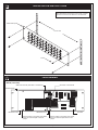
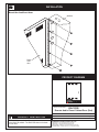
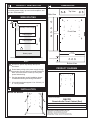
INSTALLATION
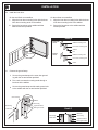
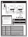
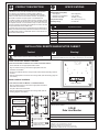
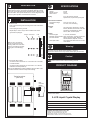
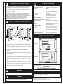
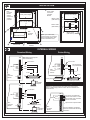
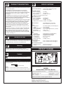
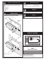
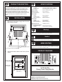
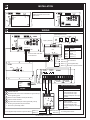
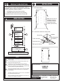
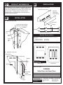
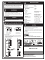
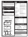
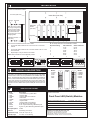
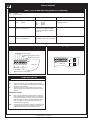
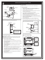
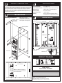
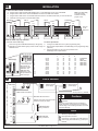
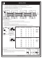
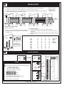
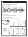
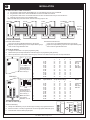
2 Make the ribbon cable connections.
A.
B.
C.
D.
Plug the ribbon cable assembly (P/N 250080) from P1 of the SAN-CPU into P2 of the 2-SANCOM.
Plug the ribbon cable from P1 of the 2-SANCOM to P2 of the next SAN series module.
Plug the ribbon cable from P1 of each SAN module to P2 of the next SAN module until you reach the last one.
Install the continuity jumper on the last SAN module.
SWU-8(/3)
JP1
P1
SRU-8
P2
SHO-4
P1
P2 JP1
Note: If the SIN-16 is
the last module,
install the continuity
jumper on JP1.
2-SANCOM
P1
P1
P2
P2
From P1
on the
SAN-CPU
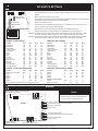
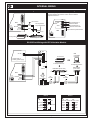
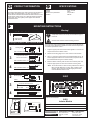
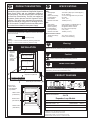
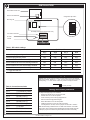
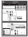
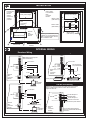
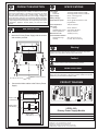
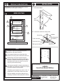
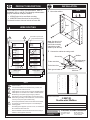
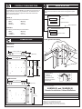
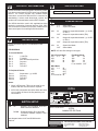
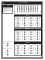
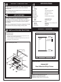
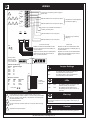
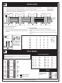
3 Set the SRU-8 dip switches.
To set the dip switches:
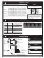
Cannot occupy the 2-SANCOM addresses (01 through 09). A. Configure the SAN-CPU in the system programming utility.
Requires one output address group, which consists of eight B. Note the start output address of the SRU-8 in the programming utility (09
to 89).
addresses.
C. Set the dip switches on S1 to the group number of the SRU-8’s start output
address.
Remember that the SRU-8:
ON 1
2
3
4
Group number
S1
SRU-8
S1
In this example, the
start address is 17
and the dip switches
are set to a binary 3.
1
2
3
4
5
6
7
8
9
10
11
12
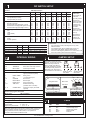
Output addresses S1 dip switch settings
1
2
3
4
01-08
09-16
17-24
25-32
33-40
41-48
49-56
57-64
65-72
73-80
81-88
89-96
off
off
off
off
off
off
off
on
on
on
on
on
on
off
on
off
on
off
on
off
on
off
on
off
off
on
on
off
off
on
on
off
off
on
on
off
Module
off
off
off
on
on
on
on
off
off
off
off
on
2-SANCOM
SHO-4
SRU-8
SWU-8(/3)
SWU-(8/3)
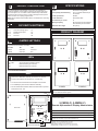
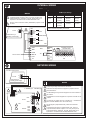
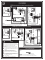
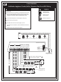
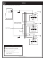
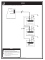
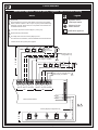
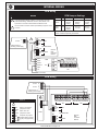
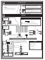
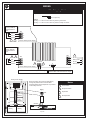
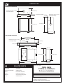
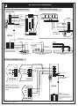
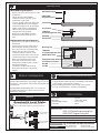
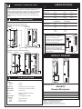
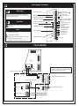
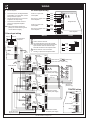
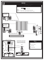
FIELD WIRING
Note: Power-limited if the source is power-limited. If the source is
nonpower-limited, maintain a space of 1/4 inch from power-limited wiring.
Otherwise, use FPL, FPLP, FPLR, or an equivalent in accordance with
the National Electric Code.
TB1
K1
K2
K3
K4
TB2
1
1
2
2
3
3
4
4
5
5
6
6
7
7
8
8
9
9
10
11
10
11
12
12
K5
K6
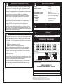
SRU-8 Relay Table
Terminal Relay
Description
Terminal Relay
Description
TB1-1
TB1-2
TB1-3
TB1-4
TB1-5
TB1-6
TB1-7
TB1-8
TB1-9
TB1-10
TB1-11
TB1-12
NC
COM
NO
NC
COM
NO
NC
COM
NO
NC
COM
NO
TB2-1
TB2-2
TB2-3
TB2-4
TB2-5
TB2-6
TB2-7
TB2-8
TB2-9
TB2-10
TB2-11
TB2-12
NC
COM
NO
NC
COM
NO
NC
COM
NO
NC
COM
NO
K1
K1
K1
K2
K2
K2
K3
K3
K3
K4
K4
K4
K5
K5
K5
K6
K6
K6
K7
K7
K7
K8
K8
K8
Detail
K7
K8
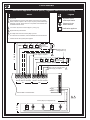
To the control circuit
24 Vdc, 4A max.
rated for pilot duty
P/N: 387207 REV: 2.0 Page 2 of 2
Typical layout for a
single pole double
throw (SPDT) relay
terminal
NC
COM
NO