1
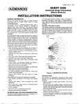
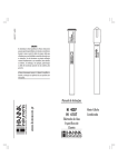
IN,TERNATIONAL 144T CULTIVATOR SETTING UP INSTRUCTIONS OPERATOR'S MANUAL ® To The Owner Your new InternaHonal Harvester cultivator is designed to meet today's exacting opera t ing requirements. The ease of operation, and ability to adjust to field conditions lighten yourwork and shorten your hours on the job. You are urged to consult your local Interna tional Harvester dealer concerning unusual conditions or special applications. let the experience of your dealer and the organiza tion associated with him serve you. Be sure to read the instructions for Adjusting and Operating in this manual'. Check each item referred to and acquaint yourself with the adjustments required to obtain effici'ent operation and maximum trouble-free service. Remember, a cultivator which is properly lubricated and adjusted saves time, labor, and fuel. Afterthe operaHng season, thoroughly clean your cuilivator and inspect it. Preve ntive maintenance pays dividends. Your dealer has original-equipment parts which assure properfit and best performance. He is able to recondition your equipment to a like-new condition. When in need of parts for the cu Itivator basic unit, always specify the serial number in c'luding any prefix or suffix letters. The serial number of the cultivator is located on the lift arm on right side. Write this serial number in the space provided bellow. A standard of metric measurement known as International System of Units (SI) has been adopted for world- w ide use. English Units followed by Metric Equivalents are used throughout this manual. (Metric Equivalents are given in parenthesis.) 1 - Cultivator serial number _ _ _ _ __ TECHNICAL PUBLICATIONS AVAILABLE !--------------------------------- Cu t Along This Line ------------------------------ Tit le Your International Harvester Dealer and his f actory t rained servicemen are best qual if ied to service your equipment . Up t o-date instructions and ad equate special tools are also a part of your Dealer's service facil ities. Number Price Each Qty. Operat or' s Ma nual Cultivator, 14 4 T .... __ . . . .. .. ... 1.70 1 696563 R Parts Catalog Cu rrent Cultivators .. . .. ... . . . .. CU-s 4.90 I This Operator's Manual was prepared to instruct you in proper operation and maintenance of your equipment. If y ou desire additional information you may purchase Service Manuals and/or Parts Catalo gs. Additional copies of the Operator's Manual are also available. Servi c e Ma n ual I Not Available ~ TOTAl ____________ ·S Fill out the order blank and forward -I together with your ch eck or money ~ order in the appropriat e amount (U.S. ~ Funds) to: .£? <:( ..... Intern ational Harvester Company PRINTING AND DISTRIBUT ION SERVICES d Please Print Nlme _________________________________________ 807 Blackhawk Dri ve Street Address _ _ _ _ _ _ _ _ _ _ _ _ _ _ _ _ __ Westmont , Illinois 60559 A ttention : Cashier City ________________ s ~~ ~~ ________________ ________________________ Zip Code Date S~ned Do not send cash or SUmps Prices subject to change without notice. CONTENTS INTRODUCTION 2, 3 WORK SAFELY - FO LLOW THESE RULES 4 ENERGY CO NSERVATION - FOLLOW THESE RECOMME NDATIONS 5 ADJUSTING AN D OPERATING Three Point Hitch Position Control Lever Auxilliary Hydraulic Control Lever General Gang Beam Take-up Bolts Pressure Springs Ground Tools Height of Lift Shield Adjustable Rear Gang Beams Wedge Bolt Clamps Road Transport Preparation 6 to 10 6 6 7 7 7, 8 9 8 9 10 10 10 STORAGE 11 SETTING UP 1 2 to 15 OPTIONAL EQUIP MENT Rear Section 21 Disk Hiller 22 Disk Hiller 122 Shield 16, 17 16 17 17 17 A CAUTION 1 INTRODUCTION Cultivator on tractor 6 16 tool equipment and opt ional rea r sect ion show n The International 144T Cultivator is a one row cultivator deSigned for use on the Inter national 274 Tractor with hydraulic lift sys tem. Cotton, corn, potatoes, and other crops may be cultivated when plant ed in rows spaced from 40" to 58" (1016 to 1473 mm) apart. The operator has a clear, unobstru cted view of the row due to the offset of the tractor seat. Small crops are followed accurate ly and where conditions permit, cultiv ating speedsupt04-1/2(7.2 km/h) miles per hour can be maintained. All adjustments for depth and lifting at the ends of the field are accomplished from th e driver's seat by means of the hydraulic lift system control levers. The three-point hitch pOSit ion control lever controls the rear section and the auxiliary hydraulic control lever raises or lowers the front section. Instant and pos it ive depth control enables the driver to cu ltivate hard and soft spots in the field to a uniform depth. Th e universal mounting frame consists of two parallel-action gang assemblies mounted one o n each side at the front of the tractor. Each assembly includes a frame, push pipe wit h pressure spring, parallel-acting gangs, and a tool bar attachi ng bracket. The at taching bracket is provided with a keyhole slot to facilitate attaching and detaching the grou nd w orking tools without disturbing their adjustm e nt. The cultivator gangs are easily and quickly attached or detached without distu rbing any of the set adjustments when the tractor is to be used for some other purpose. This assures the cultivator working at the same depth and in th e sam e relation to the row when it is reat tached as it did when last used. 2 INTR ODUCTION The ground working tools have 1-1/4" round standards. The standard clamps are the s'i ngle wedg&bolt type which are easily and quickly adjusted. The clamp is designed so that a single wedge bolt secures the vertical adjustment of the standard and, at the same time the position of the clamp along t he tool bar. Too.1bar extensions are provided for the sweep runn ing next to the row an d t hese have ample adjustment so the sweep may be set closer to or farther from the row, as desired. Front section tool equipments having the 16 Style Spring Trips are available as follows: The 4 16 Front Section Tool Eq uip ment includes tool bars, standard clamps four spring trip standards, two 8" (203 m ~) full sweeps, and two 10" (254 mm) half-sweeps. The 616 Front Section Tool Equipm ent incl u des t ool bars, st andard clamps six spri ng t rip standards, four 8" (203 mm) full sweeps, an d two 10" (254 mm) half-sweeps. The cultivator is available with 16 Style Spring Trip tooling equipment. The following attachments are available to meet the requirements imposed by the var ious crop and soil conditions. Disk Hillers - for throwing dirt to the row or for barring off. 122 Shields - prevents dirt from covering the crops. Rear Section - to remove tire t racks. ,, ~ . CAUTIONI Whenever dismounting from a vehicle stop all power sources, lower equipment to the ground, shut off engine, use park brake or lock, and remove key. A MA·' .... 3 WORK SAFELY - FOLLOW THESE RULES A Instructions given with this symbol are for personal safety. Be sure you and your workers follow them . A CAREFU L OPERATOR 1$ THE BEST INSURANCE AGAINST AN ACCIDENT A.ft~r servic~ng, be sure all tools, parts, or ser VICing equipment are removed from the machine. Misuse or modification of this machine can cause: - mechanical breakdown - property damage, - injury or death. Make sure that there is no one near the machine before starting it. Always use proper safety precautions. Tell your workers how to wor,k safely. Use only metric tools on metric fasteners. DURI NG OPERATION BEFO RE OPERAnNG No one other than the operator should ride on the tractor. Do not wear loose-fitting clothing; it may catch in moving parts. Do not attempt to remove any obstructions from while the cultivator is in motion. Use extreme care when making adjustments. Keep hands, feet, clothing and objects away from movi ng parts. When working under or arou nd the cu Itivator, always support the cultivator frame and row units. Do not ride on the cultivator during operation. Use extreme care when operating close to ditches, fences, or on hillsides. ON-H IGHWAY OPERATION Comply with your state and local laws gov erning highway safety, and with regulations when moving machinery on a highway. Drive at a reasonable speed to maintain complete control of the machine at all times. The S. M. V. reflector emblem should be used at all times on public roads. Also turn on the tractor flas hing yellow lights. A. _ CAUTION I aefore handling ANY equipment, READ the OPERA TOR'S MANUAL -..t..71 4 ENERGY CONSERVATION FOLLOW THESE RECOMMENDAT IONS [~1 An Energy Conservation Plan Is your best insurance against was te. Energy is Money. Don't Waste It I! An Energy Conservation Plan consists of: 1. Being sure the equipment is. properly adjusted to the task being performed . Review Opera tors Manual thoroughly . 2. Being sure the operator is thoroughly trained in the operation of the equipment. Review Operators Manual thoroughly . 3. Being sure that proper lubrication and maintenance procedures are followed . Review Operators Manual thoroughly . 4. Matching as closely as possible the tractor size (horsepower) to the implement size and soil conditions. The following additional recommendations are ma de by Product and Test Engineers to assist you in operating your equipment at maximum efficiency. To do so will allow you to get the most out of your dollars spent on energy. 1 - Keep sweeps sharpened. 2 - Operate up to 4-1/2 M. P. H. 5 ADJUSTING AND OPERATING THREE POINT HITCH POSITIO N CONTROL LEVER AUXILIARY HYDRAULIC CONTROL LEVER 1 2 3 4 5 1 - Three poi nt hitch position co ntrol lever 2 - Maximum rai sed position 3 - Maximum lowered position 4 - Lever lock latch The lever is used to raise or lower the equip ment mou nted to the three point hitch. A CAUTI ON ! When transporting the tractor on t he road with the equi ~ ment mounted on the three point hitch, always lock the control lever w ith the latc h at the highest position. • . • . Auxiliary hydraulic control lever Raise pos ition Lower position Neutral latch Lever lock latch The double acting auxil iary control valve is provided on the three point hitch position control valve and operated by the lever. The au xiliary control valve actuates the auxiliary hydrau lic cylinder and raises or lowers th e mid-mounted cultivator. A n adjustable stop collar on the ~ylinder rod w ill automatically stop the cylinder at a pre-set depth. A CAUTION! Never park equipment in the raised position. Mov ing the co ntro l lever w ill lower the equi ~ me nt even tho ugh th e en g ine is not running. If it is necess ary to service the equipm ent in th e ra ised position, use jackstands to safely bl ock the equipment in place. When the lever is moved to the rear, the auxiliary hydraulic cylinder retracts to raise the cultivator. 6 ADJ USTING AND OPERATING GEN ERA L Extra weight on the tractor wheels is reco m mended for cultivating hillside fields and to better stabilize the tractor. For this purpose, liquid in the tires (such as calcium chlori de solution) or wheel weights (avai lable on special order) may be used. NOTE: Before operating the cult ivator, be sure all bolts and set screws are perfectly tight, and all cotters are spread to keep them from falling out. A GANG BEAM TAKE-UP BOLTS The gang beam bearings and the tool bar clamps on the front section are provided with split bearings with take-up bolts "A". These bolts are provided to remove any side play in the gangs. Keep them d rawn up as the bearings wear but not so tight as to cause the gangs to bind. CAunoNI No riders. . .' .... a PRESSURE SPRI NGS For ordi nary working conditions, the pressure springs "B" should be set so aslight pressure is exerted on the g angs. In hard ground, it may be necessary to increase the spring pressure. Front Section: To increase the pressure on t he gangs, rai se the cu lt ivator, loosen set screw "G", st retch the spring to give the desired tension, and tighten t he set screw securely. 7 ADJUSTI NG AND OPERATING Rear Section: To increase the pressure on the gangs, raise the cultivator, loosen set screw" D", compress the spring to give the desired tension, and tighten the set screw securely. Be sure that set collars" F" are also secure. For normal working conditions, coillar "F" works best if set next to cotter pin. NOTE: If the gangs do not penetrate properly after making these adjustments, check the settings of the shovels. ~- 25" (Maximum) 23-1/2" (Minimum) __ , ~. l. _ cd · 6~~~.:r~.ft~~~~~~~,~<,~?~?>:~·~~.~-~~.d ) 6. I The height of lift may be controlled by the length at which the lift rods are set or by the auxiliary hydraulic control lever stop. Which ever method is used to determine the height of lift, be sure the machine does not strike the tractor when raised. Lift Rod Adjustment 1. Loosen the set screw" E" on both rods. 2. Push the auxiliary hydraulic control lever to the extreme forward position. 3. Raise t he right gang until the lift arm strikes the gear housing and then lower it slightly and tighten the set screw" E" in this position. AUTION I R•• d Op .rator'. Uan...1before dll.s.embly of a 4. Raise the left gang until it is level with the right and tighten the set screw" E". loaded spring. 5. Tighten the jam nuts so the set screws cannot come loose. ~ .....·111850 HEI GHT OF LIFT The height of lift for the front section will neo essar'ily be limited by the under side of the tractor. The amount of space provided for lift ing will vary with the different styles of equip ment and the various attachments. Ample adjustment is provided to give maximum lift to any of t he various ground tools th at may be used, but a careful check must be made as each machine is set u p or re mounted to see that it does not strike the tractor when raised . Minimu m Lift Rod Setting: If the lift rods are set shorter than the minimum length, damage to the mounting frame may occur if the gangs are lowered to the lowest possible position. Maxi mu m Li ft Rod Setting: If the lift rods are set longer than the maximum length, damage to the mounting frame or tractor may occur if the gangs are raised as high as possible. 8 ADJUSTING AND OPERATING GROUND TOOLS Standard Adj ustment It i,s important to operate the cultivator wit h the standards adjusted to a vertical position, and the shovels or sweeps poi nting directly forward. When t his is do ne, more accurate spaci ng of the tools is obtained, and t he standard shanks will function properly when an obstruction is encountered in t he fi eld. The shan ks are all adjustable to give the proper pitch to the sweeps or shovels. Spring Trips Spring trips are adjusted at t he factory t o t rip properly and will work until all ordinary con di tions. Adjustment should not be c hang ed unless absolutely necessary. The pitch of the sweeps (or shovels) may be changed on the 16 Spring Trips by turning the adjusting bolt indicated at" N". SHIELD The height of the shield above the row is controlled by adjusting the clip " J". To adjust the shield, loosen the rear bolt in the shield support, set the shield as desired, bring the clip to bear against the pivot link, and tighten th e bolt securely. To move the shield toward or away from the row, loose n t he U-bolt" K" holding the shield to the tool bar extension and adjust as desired. Spring trips may be made to trip harder by tightening the spring nut " J" . To do this, simply grasp the spring and turn it by hand, which in turn will usually turn the nut unless the nut has become rusty during use. Awood packing block will be fou nd betw een the adjusting bar and the sprin g bracket at "K" on the 16 Spri ng Trip. Make certain these wood blocks are removed before using the cultivator. 16 Spring Trip. 9 ADJUSTING AND OPERATING ADJUSTABLE REAR GANG BEAM S The gang beams forthe rear sections may be set so the sweeps run direcHy behind the tractor rear wheels for wheel treads ranging from 40" to 58" (1016 to 1473 mm). To Loosen the Clamps: Back off the nut until it is near the end of the wedge bolt and strike the end of the wedge bolt with a hammer. Use care not to strike the corners of the nut orthe threads may become damaged. Do not pull other implements with the rear sections attached. ROAD TRANSPORT PREPARATION Be sure that the cult ilv ator is in the fully raised position before transporting. MA-19103 WEDGE BOLT C LAMPS It is important that the wedge bolt clamps be tightened securely so that the spring trip does not come loose. This is easily done by .using a hammer and wrench as shown. To Tighten the Clamps: Drive the wedge bolt in place with a hammer. Tighten the nut with a wrench and, at the same time strike the head of the wedge bolt with the hammer. Continue to do this until the wedge bolt i1s tight. Drive at a reasonable speed to maintain complete cantra ll of the machine at all times. Comply wi th your state and local laws and regu l1ations governing highway safety when moving machinery on a highway. Be sure that all safety reflectors, and SMV emblem are wiped clean before transporting. Be sure that all safety reflectors and the S. M. V. emblem are not obscured from traffic. The S.M.V. emblem should be used at all times on public roads. Also turn on the tractor flashing yellow lights. 10 STORAGE Inspect the machine for any worn or broken parts and replace. Shelter the machine in a dry place. Clean the machine of all dirt, trash, etc. If left on, it will hold moisture and thus cause serious damage from rust. Lubricate the machine completely following the instructions under "Lubrication". Repaint any bare or rusted spots. 11 SETTING UP STE P 1. GENERAL NOTE: The cultivato r is designed for use on International®274 Tractor havi ng rear wheels equipped with maximum t ire size of 12.4- 24 tires. Remove all wires and arrange the parts ~onveniently. Lubricate all moving parts and see that they work freely. Whenever the terms " left" and "right" are used, it should be understood to mean from a position behind and facing the tractor. Bolts and pins must be used in the holes in which they are found, or in the parts to which they are attached, unless otherwise shown. During assembly, tighten the bolts to the nu mber of foot-pounds or (Newton Meters) as indicated in the table unless otherwise specified. Use only met ric tools on metric fasteners. ENGLISH BOLT TORQUE IN FOOT POUrt,JDS AND NEWTO N METERS Bolt Dia. Inches 1/4 5/16 3/8 7/16 1/2 5/8 3/4 7/8 1 Type 1 Ft. (N-m) Ibs. TypeS Ft. (N-m) Ibs. 6 13 23 37 55 104 185 315 445 10 20 35 57 85 170 305 445 670 (8) (18) (31 ) (50) (75) (141 ) (251) (427) (603) (14) (27) (47) (77) (115) (230) (414) (603) (908) Type 8 Ft. (N-m) Ibs. 13 (18) 29 (39) 48 (65) 80 (108) 123 (167) 235 (319) 425 (567) 690 (936) 1050 (1424) M ETRIC BOLT T ORQUE IN N EWTON METERS Nominal Thread Diameter ( mm) M6 M7 M8 M10 M12 M14 M16 M18 M20 M22 M24 NOTE: For plated bolts use 85% of chart figures. U- BOLT TORQUE Use type 1 torque of comparabl e size bolts. 12 Class 5.8 Class 8.8 Class 9.8 - Mi n. Max. Mi n. Max. Min. Max. 7 12 17 34 59 94 146 1202 1 285 389 493 8 13 19 38 66 106 164 227 321 437 554 11 19 27 54 94 150 233 323 456 622 788 13 21 31 61 106 169 263 363 513 699 886 13 21 30 60 105 168 261 14 24 34 68 118 189 293 - _. - - - SETTI NG UP STEP 2. UNIVERSAL MOUNTING FRAME Right side of tractor. 1. Sl ide the left frame bar into the square housing base and tighten the hex. head bolts. 2. Slide th e right frame bar into the square hous.ing base and tighten the hex. head bolts. NOTE: International 274 Tractors with seri al numbers 8329 and below may requ ire a shim, part No. 1 264 077 C1, to remove looseness between the square hou sing and the cultiva tor frame bars. Order from se rvice parts. MA·19105 3. Attach the lift rods to the lift arms and to the auxiliary hydraulic arms as shown. NOTE: See"HEIGHTOF LIFT" i,ntheAdjust ing and Operating Instructions before at tempting to ope rate the machine. 1 - Square housing 2 • Shim 13 SETIING UP STE P 3 . FOUR-SWEE P FRON T SECTION 4 16 T ool Equipment 1. Attach the tool bar assemblies to the mounting frame. 2. Bolt the sweeps to the standards, with the half sweeps on the short standards. 4. Loosen the tool bar extension clamps and adjust the standards closer to or farther from the row, as desired. Tighten the clamp securely after making an adjustment. 3. Attach the standards to the tool bars, with the long standards in the rear and the short standards, with the half sweep, next to the row. 14 SEnl NG UP STEP 3 . SIX-SWEE P FRONT SECTION 6 16 Tool Equipme nt MA-19107 1. Attach the tool bar assemblies to the mounting frame. 2. Bolt the sweeps to the standards. 4. Loosen the tool bar extension clamps and adjust the standards closer to or farther from the row, as desired. Tighten the clamp secu re ly afte r making an adjustment. 3. Attach the standards to the tool bars, with the short standards next to the row. 15 OPTIONAL EQUIPMENT REAR SECTION MA-19108 NOTE: For rear sections, the fixed drawbar must be removed. If the tractor has a three point hitch, the stabilizer and lower li nks must be removed before attaching the rear section gangs. beam so that lift rod clears t he power take-off sh ield. Also, ma ke sure that at fu ll lift, the clamps" B" do not strike the tire. 4. Attach th e pressure rod with spring to the lift rod bracket and secu re with set collar and cotter pin. Attach t he other end of the lift rod to the t ractor rockshaft arm and secure with t he klik pin. Refer to " Pressure Springs" in " ADJUSTING A D OPERATING" section. 1. Attach the bearing mounting bracket to the rear attaching pad on t he rear axle housing. 2. Insert the gang beams into t he mounting bracket. Secure with washer (1 .28 x 2.0 x 054 ga.) and klik pin. 5. Bolt the sweeps to the standards. 6. Raise the gangs and attach the stan dards to the gangs with the wedge-bolt clamps. 3. Bolt the lift rod bracket to the gang beam with U-bolt and nuts. NOTE: Position th e brackets" A" close to the bend of the gan9 16 OPTIONAL EQUIPMENT 21 DI SK HILLER 1. Remove the standards next to the row and clamp the disk hillers in place as shown. 22 DISK H ILLER 1. Remove th e standards next to the row and cl am p the disk hillers in place as shown. 122 S H IELD Spring Trip T ool Equipment 1. Attach the shield to the tool bar extens ion as shown, and adjust it in relation to the row as desired. 17 MEMORANDA 18 MEASUREMENT UNITS Metric Equivalent (51) Engli sh Un it Area 1 square inch (in 2 ) 1 acre 6.45 square centimetre (em 2) 0.405 hectare(ha) Force 4.45 newton (N) 1 pound-force (lbf) Leng th 304 .8 millimetre (mm), 30.5 centimetre (em), 0.305 metre (m) 25.4 millimetre (mm), 2.54 centimetre (em) 1609 metre (m) , 1.61 kilometre (km) 1 foot (tt) 1 inch (in) 1 mile Mass 0.454 kilogram (kg) 1 pou nd (lb) Power 0 .746 kilowatt (kW) 1 horsepower (hp) Pressure 1 pound-force per square inch, psi (lbf lin 2 ) 6.89 ,k ilopascal (kPa), 0.0068 9 mega pascal (MPa) Temperature t degree Fahrenheit (OF) (t - 32) degree Celsius (·C) 1.8 Torque 1 pound-torce foot (lbf·ft) 1.356 newton metre (N' m) Velocity 1 mile per hour (mph) 1.61 kilometre per hour (km/h) Volume 1 US bushel 1 US gal.lon (US gal) 1 US quart (US qt) 0 .035 cubic metre (m 3 ) 3 .79 IHre (L) 0 .946 litre (U , INTERNATIONAL HARVESTER COMPANY 401 NORTH MICHIGAN AVE. / CHICAGO, ILLINOIS 60611/ U.S.A. 1 096 563 R2. 9-81. PAINTED IN UNITED STAT£S OF AMERICA