1
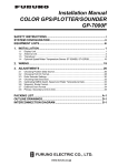
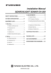
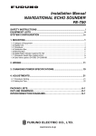
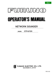
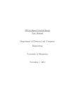
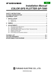
COLOR LCD SOUNDER
MODEL
FCV-582L
SAFETY INSTRUCTIONS
CAUTION
WARNING
ELECTRICAL SHOCK HAZARD
Ground the equipment to
prevent electrical shock and
mutual interference.
Do not open the equipment
unless totally familiar with
electrical circuits and
service manual.
Observe the following compass safe
distances to prevent deviation of a
magnetic compass:
Only qualified personnel
should work inside the
equipment.
Display
unit
Turn off the power at the switchboard
before beginning the installation.
Fire or electrical shock can result if the
power is left on.
Standard
Steering
0.6 m
0.6 m
When handling the transducer cable,
keep in mind following points.
. eep the cable away from oil and
fuel.
. Keep the cable away from the
place where it may be damaged
during the installation.
. Do not paint the cable.
The sheath of the transducer cable is
made of chlorophrene rubber (or vinyl
chloride). Therefore, do not paint the
sheath with organic liquid (such as
toluene) since it may harm the sheath.
Do not install the equipment where it
may get wet from rain or water splash.
Water in the equipment can result in fire,
electrical shock or equipment damage.
Be sure no water leaks in at the transducer installation site.
Water leakage can sink the vessel. Also
confirm that the transducer will not loosen
by ship’s vibration. The installer of the
equipment is solely responsible for the
proper installation of the equipment.
FURUNO will assume no responsibility for
any damage associated with improper
installation.
Be sure that the power supply is
compatible with the voltage rating of
the equipment.
Connection of an incorrect power supply
can cause fire or equipment damage. The
voltage rating of the equipment appears
on the label above the power connector.
i
i
TABLE OF CONTENTS
EQUIPMENT LISTS ......................................................................................................iii
SYSTEM CONFIGURATION .................................................................................... iv
MOUNTING
1.1 Display Unit ........................................................................................................................ 1
1.2 Thru-hull Mount Transducer 520-5PSD, 520-5MSD ......................................................... 3
1.3 Transom Mount Transducer 520-5PWD,
Optional Transom Mount Triducer 520ST-PWD................................................................ 6
1.4 Inside-hull Mount Transducer 520-5PSD, 520-5MSD ....................................................... 8
1.5 Optional Water Temperature/Speed Sensors..................................................................... 11
1.6 Optional Water Temperature Sensors ............................................................................... 12
1.7 Optional Triducer 524ST-MSD, 525ST-MSD .................................................................. 14
WIRING
2.1 Wiring ............................................................................................................................... 15
2.2 Optional Sensors ............................................................................................................... 17
2.3 Optional 50 kHz and 200 kHz Transducers ...................................................................... 19
EXTERNAL EQUIPMENT SETUP
3.1 External Equipment Setup ................................................................................................ 20
APPENDIX TRIDUCER 525ST-PWC/PWD ................................................. AP-1
PACKING LIST ............................................................................................................. A-1
OUTLINE DRAWING ................................................................................................. D-1
INTERCONNECTION DIAGRAM ........................................................................ S-1
ii
EQUIPMENT LISTS
Standard Supply
No.
Name
Type
Code No.
Qty
—
1
1
Display Unit CV-582L
2
Installation
Materials
CP02-06100
000-015-468
1 set
3
Spare Parts
SP02-03900
001-389-000
1 set
4
Accessories
FP02-04800
000-015-406
1 set
520-5PSD
000-015-125
520-5MSD
000-015-127
520-5PWD
000-015-126
5
Transducer
Remarks
See packing list at end of
manual.
Inside-hull
Select
Inside-hull, w/8 m cable
one
Transom mount, w/8 m cable
Optional Supply
No.
Name
1
Rectifier
2
Cable Assy.
3
Cable Assy.
4
5
Triducer
Temperature
Sensor
Type
PR-62
Code No.
—
MJ-A6SPF0012-050
000-134-424
6P-6P, 5 m
MJ-A6SPF0012-100
000-133-817
6P-6P, 10 m
MJ-A6SPF0011-050
000-132-244
6P-4P, 5 m
MJ-A6SPF0011-100
000-132-336
6P-4P, 10 m
524ST-MSD
000-015-224
525ST-MSD
000-015-263
520ST-PWD
000-015-128
525ST-PWD
000-015-261
T-02MTB
000-040-026
With 8 m cable, transom mount
T-02MSB
000-040-040
Thru-hull type
T-03MSB
000-040-027
With 8 m cable, thru-hull type
ST-02MSB
000-137-986
Thru-hull type
ST-02PSB
000-137-987
With 8 m cable, thru-hull type
6
ST Sensor
7
Inside Hull
Kit S
22S0191-0
000-802-598
8
Distributor Kit
MB-1000
000-040-809
50B-6
000-015-042
50B-6G
000-015-016
200B-5
000-015-027
200B-5S
000-015-029
9
Transducer
Remarks
Thru-hull type
Transom mount type
Requires Distributor MB-1000.
10
Converter
Connector
02S4089
000-133-622
8P→10P
11
Converter
Connector
02S4147
000-141-082
Water temperature/Speed
sensor
12
Converter
Connector
02S4093
000-134-901
Transducer of AIRMAR
CORP.
13
Converter
Connector
02S4167
000-142-503
Extends standard transducer
cable 10m.
iii
SYSTEM CONFIGURATION
STANDARD SUPPLY
OPTIONAL SUPPLY
MJ-A3SPF
3P
6P
DISPLAY UNIT
CV-582L
Navigator
6P
Speed/water temperature:
ST-02MSB, ST-02PSB
OR
Water temperature sensor:
T-02MSB, T-02MTB,
T-03MSB
MJ-A15A3F0013-035-3A
10P
3.5m
12-24 VDC
Transducer
520-5MSD
520-5PWD
520-5PSD
10P
8P
8P
DISTRIBUTOR
MB-1000
50B-6/6G
200B-5/5S
10P
Triducer
524ST-MSD
520ST-PWD
iv
MOUNTING
1.1 Display Unit
Mounting considerations
The display unit can be installed on a tabletop or on the overhead.
When selecting a mounting location for the display unit keep the
following in mind:
• Keep the display unit out of direct sunlight.
• The temperature and humidity should be moderate and stable.
• Locate the unit away from exhaust pipes and vents.
• The mounting location should be well ventilated.
• Mount the unit where shock and vibration are minimal.
• Keep the unit away from electromagnetic field-generating equipment such as motors and generators.
• For maintenance and checking purposes, leave sufficient space
at the sides and rear of the unit and leave slack in cables.
• A magnetcompass will be affected if placed too close to the
display unit. Observe the following compass safe distances to
prevent disturbance to the magnetcompass:
Standard compass: 0.8 meters
Steering compass: 0.6 meters
Cover
Tabletop
Overhead
Figure 1-1 Display unit mounting methods
1
Removing cover
While pressing the center of the cover with your thumbs as illustrated, pull the cover towards you to remove it.
Mounting procedure
Attach blind film
to unused knob
holes.
Figure 1-2 How to set the display unit to the hanger
2
1.2 Thru-hull Mount Transducer 520-5PSD, 520-5MSD
Transducer mounting location
This type of mounting provides the best performance of all, since
the transducer protrudes from the hull and the effect of air bubbles
and turbulence near the hull skin is reduced. When the boat has a
keel, the transducer should be at least 30 cm away from it. Typical
thru-hull mountings are shown in the figure on the next page.
The performance of this sounder is directly related to the mounting location of the transducer, especially for high-speed cruising.
The installation should be planned in advance, keeping the standard cable length (8 m) and the following factors in mind:
• Air bubbles and turbulence caused by movement of the boat
seriously degrade the sounding capability of the transducer. The
transducer should, therefore, be located in a position where water flow is the smoothest. Noise from the propellers also adversely affects performance and the transducer should not be
mounted nearby. The lifting strakes are notorious for creating
acoustic noise, and these must be avoided by keeping the transducer inboard of them.
• The transducer must always remain submerged, even when the
boat is rolling, pitching or up on a plane at high speed.
• A practical choice would be somewhere between 1/3 and 1/2 of
the boat’s length from the stern. For planing hulls, a practical
location is generally rather far astern, so that the transducer is
always in water regardless of the planing attitude.
Transducer outline drawings
22
24
120
120
31
All dimensions 28
in millimeters
Ship's
bow
74
68
520-5PSD
90
520-5MSD
Figure 1-3 Dimensions of transducers 520-5PSD, 520-5MSD
3
Acceptable transducer mounting locations
Deep-V hull
• Position 1/2 to 1/3 length of the hull from stern
• 15 to 30 cm off center line (inside first lifting strakes).
Figure 1-4 Transducer mounting location on deep-V hull
High speed V-planing hull
• Within the wetted bottom area
• Deadrise angle within 15°
Figure 1-5 Transducer mounting location on high speed
V-planing hull
Typical thru-hull mount transducer installations
Fairing block
Flat washer
Rubber washer
Hull
bottom
Hull
bottom
Deep-V Hull
Flat Hull
Figure 1-6 Typical thru-hull mount transducer installations
4
Procedure for installing the thru-hull mount
transducer
1. With the boat hauled out of the water, mark the location selected for mounting the transducer on the bottom of the hull.
2. If the hull is not level within 15° in any direction, fairing blocks
made out of teak should be used between the transducer and
hull, both inside and outside, to keep the transducer face parallel with the water line. Fabricate the fairing block as shown
below and make the entire surface as smooth as possible to
provide an undisturbed flow of water around the transducer.
The fairing block should be smaller than the transducer itself
to provide a channel to divert turbulent water around the sides
of the transducer rather than over its face.
Hole for
stuffing tube
Upper
half
BOW
Lower
half
Saw along slope of hull.
Figure 1-7 Construction of fairing block
3. Drill a hole just large enough to pass the threaded stuffing tube
of the transducer through the hull, making sure it is drilled vertically.
4. Apply a sufficient amount of high quality caulking compound
to the top surface of the transducer, around the threads of the
stuffing tube and inside the mounting hole (and fairing blocks
if used) to ensure watertight mounting.
5. Mount the transducer and fairing blocks and tighten the locking nuts. Be sure that the transducer is properly oriented and its
working face is parallel to the waterline.
Note: Do not over-stress the stuffing tube and locking nuts through
excessive tightening, since the wood block will swell when the
boat is placed in the water. It is suggested that the nut be tightened
lightly at installation and retightened several days after the boat
has been launched.
5
1.3 Transom Mount Transducer 520-5PWD,
Optional Transom Mount Triducer 520ST-PWD
This type of mounting is very commonly employed, usually on
relatively small I/O or outboard boats. Do not use this method on
an inboard motor boat because turbulence is created by the propeller ahead of the transducer.
There are two methods of installation: flush with hull (for flat hulls)
and projecting from hull (for deep V-hulls).
D
D>50 cm
Flat Hull
Deep V-hull
Figure 1-8 Transom mount transducer mounting locations
Installing the transom mount transducer flush with
hull (for flat hulls)
A suitable mounting location is at least 50 cm away from the engine and where the water flow is smooth.
1. Drill four pilot holes in the mounting location.
2. Attach the transducer to the bracket with tapping screws (supplied).
3. Adjust the transducer position so the transducer faces right to
the seabed.
Note: If necessary, to improve water flow and minimize air
bubbles staying on the transducer face, incline the transducer
about 5° at the rear. This may require a certain amount of
experimentation for fine tuning at high cruising speeds.
4. Fill the gap between the wedge front of the transducer and transom with epoxy material to eliminate any air spaces.
6
M5 x 20
M5 x 20
5°
Tape
No. 1 M5 x 14
Figure 1-9 Transom mount transducer, mounting flush with hull
Installing the transom mount transducer projecting
from hull (for deep-V hulls)
This method is employed on deep-V hulls and provides good performance because the effects of air bubbles are minimal. Install
the transducer parallel with water surface; not flush with hull. If
the boat is placed on a trailer care must be taken not to damage the
transducer when the boat is hauled out of the water and put on the
trailer.
M5 x 20
M5 x 20
No. 2
M5 x 14
Figure 1-10 Transom mount transducer, projecting from hull
Transducer preparation
Before putting the boat in water, wipe the face of the transducer
thoroughly with a detergent liquid soap. This will lessen the time
necessary for the transducer to have good contact with the water.
Otherwise the time required for complete “saturation” will be
lengthened and performance will be reduced.
Do not paint the transducer. Performance will be affected.
7
1.4 Inside-hull Mount Transducer 520-5PSD, 520-5MSD
Necessary tools
You will need the following tools:
• Sandpaper (#100)
• Silicone sealant
• Silicone grease
Remarks on installation
• Turn off the engine and anchor the boat while installing the equipment.
• Install the transducer in the engine room.
Selecting the mounting location
Keep the following points in mind when selecting a mounting location:
• The mounting location should be where the hull is of singlehull thickness and is void of air or flotation materials other than
solid fiberglass between the transducer face and the water.
• Do not place the transducer over hull struts or ribs which run
under the hull.
• Avoid a location where the rising angle of the hull exceeds 15°,
to minimize the effect of the boat’s rolling.
• You will finalize the mounting location through some trial and
error. The procedure for this is shown later.
Center line
50cm
50cm
1/2
1/3
15cm
15cm
Mounting location
for transducer
Figure 1-11 Inside-hull transducer mounting location
8
Attaching the transducer
1. Clean the transducer face to remove any foreign material.
Lightly roughen the transducer face with #100 sandpaper. Also,
roughen the inside of the hull where the transducer is to be
mounted.
2. Warm the silicone sealant to 40°C before usage to soften it.
Coat the transducer face and mounting location with silicone
sealant.
Transducer face
Silicone sealant
Figure 1-12 Coating the transducer face with silicone sealant
3. Press the transducer firmly down on the hull and gently twist it
back and forth to remove any air which may be trapped in the
silicone sealant.
Squeeze out
air bubbles.
Hull
Silicone
sealant
Figure 1-13 Attaching transducer to hull with silicone sealant
9
Checking the installation
1. Connect the battery to the display unit as shown on page 15.
2. Turn on the display unit.
3. Operate the MODE control to select LF or HF.
4. Press the GAIN control to select OFF (if it is not already selected).
5. Set the gain to “5” with the GAIN control.
6. Operate the RANGE control to set the range to 30 feet.
7. If the bottom is displayed in red and the depth indication appears the mounting location is suitable. You can leave the transducer in position.
--.-°C
---kt
50k
0.0
0
2
Transmission
line
4
6
Reddishbrown
Bottom
8
Depth
6.5
10
Figure 1-14 Sounder display
8. If the bottom is not displayed in red, the mounting location is
unsuitable. Do the following:
1) Press the POWER key to turn off the power.
2) Gently dismount the transducer with a piece of wood.
3) Reattach the transducer elsewhere as shown in “Attaching
the transducer.”
4) Check the installation again.
Final preparation
Support the transducer with a piece of wood to keep it in place
while it is drying. Let the transducer dry 24–72 hours.
10
1.5 Optional Water Temperature/Speed Sensors
Through-hull mount water temperature/speed sensor
ST-02MSB, ST-02PSB
Select a suitable mounting location considering the following:
• Select a mid-boat flat position. The sensor does not have to be
installed perfectly perpendicular. The sensor must not be damaged in dry-docking operation.
• Select a place apart from equipment generating heat.
• Select a place in the forward direction viewing from the drain
hole, to allow for circulation of cooling water.
• Select a place free from vibration.
1. Dry-dock the boat.
2. Make a hole of approx. 51 mm diameter.
3. Unfasten locknut and remove the sensor section.
4. Apply high-grade sealant to the flange of the sensor.
5. Pass the sensor casing through the hole.
6. Face the notch on the sensor toward boat’s bow and tighten the
flange.
7. Set the sensor section to the sensor casing and tighten the locknut.
8. Launch the boat and check for water leakage around the sensor.
Locknut
Face "notch"
toward bow.
51
Flange nut
Coat with
silicone sealant.
123
Brim
ø77
Figure 1-15 Water temperature/speed sensor ST-02MSB,
ST-02PSB
11
1.6 Optional Water Temperature Sensors
Transom mount water temperature sensor T-02MTB
• Fix the cable at a convenient location with cable clamp.
• When the cable is led in through the transom board, make a
hole of approx. 17 mm diameter to pass the connector. After
passing the cable, fill the hole with a sealing compound.
D
D>50 cm
M5 x 20
Mount sensor
flush with hull bottom.
Figure 1-16 How to install transom mount water temperature
sensor T-02MTB
12
Thru-hull mount water temperature sensor
T-02MSB, T-03MSB
• Select a mid-boat flat position. The sensor does not have to be
installed perfectly perpendicular. The sensor must not be damaged in dry-docking operation.
• Select a place apart from equipment generating heat.
• Select a place in the forward direction viewing from the drain
hole, to allow for circulation of cooling water.
• Select a place free from vibration.
T-02MSB
T-03MSB
Sensor Holder
Sensor
cable
Locknut
Locknut
Washer
Gasket
Locknut
Washer
Gasket
φ25 mm
φ21 mm
Coat with
sealant.
Mounting procedure
1. Drill a hole of 21 mm in diameter in
the mounting location.
2. Pass the sensor cable through the
hole.
3. Pass gasket, washer and locknut
onto cable in that order.
4. Coat the sensor flange with high
quality sealant and then fasten the
sensor with the locknut.
(Torque: max. 59N·m)
5. Launch the boat to check for water
leakage around the sensor.
Coat with
sealant.
Holder Guide
Plate thickness
within 25 mm
Mounting procedure
1. Drill a hole of 25 mm in diameter in the mounting
location.
2. Coat holder guide with high quality sealant, and
pass gasket, washer and locknut onto holder
guide in that order and then tighten the locknut.
3. Set the sensor holder to the holder guide from
inside the boat and then tighten the locknut.
4. Launch the boat to check for water leakage
around the sensor.
Figure 1-17 Thru-hull mount water temperature sensors
T-02MSB, T-03MSB
13
1.7 Optional Triducer 524ST-MSD, 525ST-MSD
The triducer is designed for thru-hull mounting.
Mounting considerations
When selecting a mounting location keep the following points in
mind:
• Air bubbles and turbulence caused by movement of the boat
seriously degrade the sounding capability of the transducer. The
transducer should, therefore, be located in a position where water flow is the smoothest. Noise from the propellers also adversely affects performance and the transducer should not be
mounted nearby. The lifting strakes are notorious for creating
acoustic noise, and these must be avoided by keeping the transducer inboard of them.
• The transducer must always remain submerged, even when the
boat is rolling, pitching or up on a plane at high speed.
• A practical choice would be somewhere between 1/3 and 1/2 of
the boat’s length from the stern. For planing hulls, a practical
location is generally rather far astern, so that the transducer is
always in water regardless of the planing attitude.
∅79 mm
133 mm
2.00"-12 UN
threads
7 mm
∅51 mm
27 mm
140 mm
Figure 1-18 Dimensions of triducer 524ST-MSD
14
WIRING
2.1 Wiring
All wiring are terminated at the rear of the display unit.
DISPLAY UNIT
Ground terminal
External equipment
Black
Ground
White
Shield
TRANSDUCER
BATTERY
Figure 2-1 Display unit, rear view
Power cable
Connect the power cable to the power connector. Connect the leads
to the battery (12 or 24 VDC); white to plus(+) terminal and black
to minus(-) terminal.
Cable connector
Power cable
w/fuse (3A)
Lead wire
Black
White
BATTERY
Figure 2-2 Connecting the power cable to the battery
15
Transducer, optional triducer
Connect the transducer cable to the XDR connector.
Ground
Connect the ground wire (KIV 2.0sq, 2 m, supplied) to ship’s ground
to prevent interference to the picture. Shorten the ground wire as
much as possible. For FRP vessels, install a ground plate that measures about 20 cm by 30 cm on the outside of the hull bottom to
provide a ground point.
CAUTION
Ground the equipment
to prevent mutual
interference.
Note: Use a “closed” lug to make the ground connection at the
).
display unit. Do not use an “open-type” lug (
Attaching EMI cores
Attach EMI cores to the power cable and transducer cable to prevent noise.
1. Tape the power cable and transducer cable where the EMI core
is to be attached, to fix the core.
2. Attach cores where tape is placed on respective cables.
EMI core
Figure 2-3 How to attach EMI cores
16
2.2 Optional Sensors
Water temperature sensor
Connect the transducer cable to the XDR connector. Connect the
water temperature sensor (option) or water temperature/speed sensor (option) to the XDR connector with the converter connector
(Type : 02S4147, Code No. : 000-141-082, option).
MJ-A6SRMD
MJ-A10SPF
SHIELD
TEMP
TEMP0V
NC
NC
NC
1
4
7
3
2
5
6
8
9
10
1
2
3
4
5
6
MJ-A10SRMD
NC
NC
NC
NC
NC
NC
NC
XDR+
XDR SHIELD
XDR-
1
2
3
4
5
6
7
8
9
10
NC
TEMP
TEMP0V
NC
NC
NC
NC
XDR+
XDR SHIELD
XDR-
Figure 2-4 Connection of water temperature speed sensor
Connection of water temperature/speed sensor
MJ-A6SRMD
SHIELD
TEMP
TEMP0V/SPD0V
SPD
+V
NC
MJ-A10SPF
1
2
3
4
5
6
MJ-A10SRMD
1
2
NC
NC
NC
NC
NC
NC
NC
XDR+
XDR SHIELD
XDR-
4
7
3
1
2
5
6
8
9
10
TEMP
TEMP0V
SPD0V/ SHIELD
SPD
+12.7V
NC
NC
XDR+
XDR SHIELD
XDR-
3
4
5
6
7
8
9
10
Figure 2-5 Connection of water temperature/speed sensor
17
Connect to XDR connector
at rear of display unit
MJ-A10SPF
MJ-A6SRMD
MJ-A10SRMD
Tape connector with
self-vulcanizing tape
and then vinyl tape
to waterproof
connector. Bind tape
end with cable tie.
Water temp., water temp/speed
sensor connector
Transducer connector
Figure 2-6 Connection of transducer, water temperature sensor,
water temperature/speed sensor
NMEA data sentences
18
Input/Output
Data Sentence
INPUT: L/L, Course, Speed,
Waypoint Range/Bearing,
Water Temperature,
Cross-Track Error
RMA, RMB, RMC,
BWC, GLL, MTW,
VTG, VHW, XTE
OUTPUT: Depth, Water
Temperature, Speed
Output every 2 sec.
DBT (Ver. 1.5)
DPT (Ver. 2.0)
MTW, VHW
2.3 Optional 50 kHz and 200 kHz Transducers
To connect optional transducer 50B-6, 50B-6G, 200B-5 or 200B5S, the optional Distributor Kit (MB-1000, code no. 000-040-809)
is required. Additionally, an 8P-10P converter connector (02S4089,
code no. 000-133-622) is required to connect to the display unit.
Fasten the cable from the Distributor to the XDR connector on the
display unit.
TRANSDUCER
02P6168
50kHz
J2
50B-6/50B-6G
SHIELD
RED
200kHz
Jumper block setting
J2: No output restriction
J1: Output restriction
RED
BLK
BLK
J1
TB2
1
2
3
4
TB1
Shield
WHT
3
2
1
BLK
5
200B-5/200B-5S
To display unit
(cable is fitted with
8P connector.
8P-10P converter
connector is required.)
Figure 2-7 Distributor MB-1000
Name
Type
Code No.
Qty
Distributor
MB-1000
000-040-805
1
Crimp-on Lug
FV1.25-3 Red 000-538-113
6
Cord Lock
NC-1
1
000-516-650
Remarks
Cable w/8P connector supplied for
connection to display unit
For use with separate transducer
19
EXTERNAL EQUIPMENT SETUP
This chapter shows you how to set up the FCV-582L when external equipment is connected. If a water temperature/speed sensor is
installed, you should complete this section with the boat in the
water and running, to confirm speed/water temperature readout.
Display the system menus as shown below, and then follow appropriate procedure(s) on the next page. Finish by resetting the power
and checking for proper display of data.
3.1 External Equipment Setup
Displaying the system menu 1, system menu 2
1. Select MENU by operating the MODE control.
2. Press the [▼] key to select GO TO SYSTEM MENU.
SYSTEM MENU 1
MENU 1 2 3
DEPTH UNIT m ft fa pb
SPEED UNIT kt MPH km/h
TEMP UNIT ° C ° F
ZOOM MARK OFF ON
F/A LEVEL WEAK MED STRG
TEMP GRAPH
OFF ON
LANG English
DISP SEL GRA1 GRA2 DAT
DRAFT 0.0 [-20 +20]
TX OUTPUT MIN MAX
▲▼ :
To select item
- + : To set condition
SIG LEV : ESCAPE
SYSTEM MENU 2
MENU
1
2
3
[+] at
NAV DSP OFF L/L R/B CSE
"MENU 1"
NMEA Ver1.5 Ver2.0
BEARING TRUE MAG
SPD SEL OFF
OWN NMEA
[–] at
TMP SEL OFF
OWN NMEA
"MENU 2"
SPD ADJ
0 %
[-50 +50]
TMP ADJ
0.0
°F [-20 +20]
(ADJUSTABLE OWN SENSOR ONLY)
OWN SENSOR
OWN SENSOR
TEMPERATURE
SPEED
– –. – kt
– –. – °F
To select item
- + : To set condition
SIG LEV : ESCAPE
▲▼ :
Figure 3-1 System menu 1, System men
3. Press the [+] key at GO TO SYSTEM MENU.
The System menu 1 appears. You can switch between these
menus with the [+] and [–] keys when the MENU field is
selected.
4. Follow appropriate procedure(s) on the next page.
20
Draft setup
1. At the System menu 1 press the [▼] key to select DRAFT.
2. Press the [+] or [–] key to set draft. For example, if the depth
readout is 5 feet lower than actual depth, enter +5 feet.
Navigator setup
1. At the System menu 2, press the [▼] key to select NMEA.
2. Press the [+] or [–] key to select NMEA input format of navigator; Ver. 1.5 or Ver. 2.0. (If you are unsure of the version no.,
try both and select the one which successfully inputs nav data
to the sounder.)
3. To display nav data on the sounder displays, press the [▲] key
to select NAV DSP.
4. Press the [+] or [–] key to select which nav data to display; L/
L (Position), R/B (Range and Bearing to a Waypoint), or CSE
(Course).
Speed data setup
1. At the System menu 2, press the [▼] key to select SPD SEL.
2. Press the [+] or [–] key to select source of speed data; OWN
(speed sensor) or NMEA.
3. For speed sensor-equipped sets, you may offset the speed readout if it is wrong. Run the boat at various speeds and watch the
speed readout at the bottom of the screen. If it is unreasonably
wrong, press the [▼] key to select SPD ADJ.
4. Press the [+] or [+] key to correct speed readout. For example,
if the readout is 10% higher than actual speed, enter -10.
Water temperature data setup
1. At the System menu 2, press the [ ▼] key to select TMP SEL.
2. Press the [+] or [–] key to select source of water temperature
data; OWN (water temperature sensor) or NMEA.
3. For water temperature sensor-equipped sets, you may offset
the water temperature readout if it is wrong. Watch the water
temperature readout at the bottom of the screen. If it is unreasonably wrong, press the [▼] key to select TMP ADJ.
4. Press the [+] or [–] key to correct water temperature readout.
For example, if the readout is 2° higher than actual temperature, enter -2°.
5. To display a water temperature graph (shows present water temperature), press the [▲] key to select MENU and press the [–]
key to select 1. The System menu 1 appears.
6. Press the [▼] key to select TEMP GRAPH.
7. Press the [+] key to select ON.
21
Confirming indications
1. Reset the power.
2. Confirm that appropriate data appears on the display.
Speed
Water temperature
Nav data (position)
22.6°C 12kt
35°15.000’N
135°07.500’E
200k
0.0
0
30
Water temperature
scale
Water temperature
marker (orange)
20
20
10
0
49.6
40
60
80
Figure 3-2 Location of speed, water temperature and nav data
indications
22
APPENDIX
TRIDUCER 525ST-PWC/PWD
This appendix provides a copy of the installation instructions for AIRMAR triducer. If you
loose the original supplied with the triducer, use this appendix.
INSTALLATION INSTRUCTIONS
Transom Mount Transducer or TRIDUCER
Multisensor with Integral Release Bracket
Model P66
R
Record the information found on the cable tag for future
reference.
Part No._______ Date_______ Frequency_______kHz
U.S. Patents: 4,555,938; 4,644,787; 5,606,253; Des. 334,335
Canadian Patent 1,233,341
TRIDUCER R
multisensor
IMPORTANT: Please read the instructions
completely before proceeding with the
installation. These instructions supersede any
other instructions in your instrument manual if
they differ.
CAUTION: NEVER USE SOLVENTS
Cleaners, fuel, paint, sealants, and other products may
contain strong solvents, such as acetone, which attack
many plastics greatly reducing their strength.
Applications
• Not recommended for boats with large or twin screw
inboard engine(s)
• Good operation up to 44 kn (50 MPH)
• Vertically orients sound beam on hull with deadrise
angle up to 30°
Adjusts to transom angles from 2°- 22°
Bracket protects sensor from frontal impact only
•
•
Tools and Materials
Scissors
Masking tape
Safety goggles
Dust mask
Electric drill
Drill bits:
Bracket holes
Fiberglass hull
4 mm, #23, or 9/64”
chamfer, countersink, 6 mm,
or 1/4”
Transom hole (optional) 20 mm or 13/16”
Cable clamp holes
3 mm or 1/8”
Marine sealant
Screwdrivers
Straight edge
Pencil
Zip-ties
Water-based antifouling paint (mandatory in salt
water)
Transducer
Pretest Speed and Temperature Functions
Connect the multisensor to the instrument and spin the
paddlewheel. Check for a speed reading (and the
approximate air temperature if applicable). If there is no
reading or it is inaccurate, return the instrument to your
place of purchase.
Mounting Location
To ensure the best performance, the sensor must be in
contact with aeration-free and turbulence-free water.
Mount the sensor on the transom as close to the
centerline (keel) of the boat as possible. On slower
heavier displacement hulls, positioning it farther from
the centerline is acceptable.
Headroom – Allow adequate space above the bracket
for it to release and rotate the sensor upward (see
Figure1).
Caution: Do not mount in an area of turbulence or
bubbles:
Near water intake or discharge openings;
Behind strakes, struts, fittings, or hull irregularities;
Behind eroding paint (an indication of turbulence).
Caution: Avoid mounting the sensor where the boat
may be supported during trailering, launching, hauling,
or storage.
• Single drive boat – Mount on the starboard side at
least 75 mm (3”) beyond the swing radius of the
propeller (see Figure2).
• Twin drive boat – Mount the sensor between the
drives.
min.: 127 mm (5")
headroom
max. with speed sensor:
213 mm (8-1/2")
max. no speed sensor:
191 mm (7-1/2")
Figure1. Stepped hull - headroom required at mounting location
Figure2.
Mounting
location
on single
drive boat
75 mm (3")
minimum beyond
swing radius
AP-1
APPENDIX TRIDUCER 525ST-PWC/PWD
Installation
Hole Drilling
Figure 3. Template
for starboard side of boat
Drill at locations labeled "B"
for transom angles 16° through 22°
(most small aluminum boats)
B
B
B
A
A
A
Drill at locations labeled "A"
for transom angles 2° through 15°
(most boats)
Align arrow with bottom of transom
Align template vertically
1. Cut out the template (see Figure3).
2. At the selected location on the starboard side
of the hull, position the template, so the arrow
at the bottom is aligned with the bottom edge
of the transom (see Figure4). Being sure the
template is parallel to the waterline, tape it in
place.
Warning: Always wear safety goggles and a
dust mask.
3. Using a 4 mm, #23, or 9/64” bit, drill three
holes 22 mm (7/8”) deep at the locations
indicated. To prevent drilling too deeply, wrap
masking tape around the bit 22 mm (7/8”)
from the point.
Fiberglass hull – Minimize surface cracking
by chamfering the gelcoat. If a chamfer bit or
countersink bit is not available, start drilling
with a 6 mm or 1/4” bit to a depth of 1 mm
(1/16”).
Plastic Shim
• Standard transom (13°transom angle) – The
bracket is designed for a standard 13°transom
angle. The shim is not needed for this installation.
Skip to “Mounting the Bracket”.
• Stepped transom and jet boats
(3°transom angle) – Use the shim with the
tapered end down.
• Small aluminum and fiberglass boats
(20°transom angle) – Use the shim with the
tapered end up.
• If you are unsure about using the shim,
do one of the following:
• Measure the transom angle of your boat using a
digital level or bubble level and protractor. Then
follow the instructions above for your transom
angle.
• Experiment with the shim. Follow the
instructions: “Mounting the Bracket”, “Attaching
the Sensor to the Bracket”, and “Checking the
Sensor Angle and Projection”.
Mounting the Bracket
slope of hull
parallel to
waterline
Align template arrow with
bottom edge of transom
Figure4. Template position
bracket
screw
self-tapping
screw
1. Apply marine sealant to the threads of the three,
#10 x 1-3/4”, self-tapping screws to prevent
water seepage into the transom (see Figure5).
Screw the bracket (and shim if needed) to the
hull. Do not tighten the screws.
2. Using the vertical adjustment space on the
bracket slots, slide the bracket up or down until
the distance between the bottom left corner and
the bottom of the transom equals 41 mm (1-5/8”).
Tighten the screws.
mounting ears
closed
actual size
screws
(self-tapping
#6 x 5/8")
actual size
co
ve
r
ho
us
in
g
speed
sensor
opened
tab in slot
slope
of hull
cover
flush with
housing
cover
41 mm (1-5/8")
insert screwdriver here to
remove cover
transducer
housing
Figure5. Distance between
corner of bracket and
bottom of transom
AP-2
Figure6. Speed sensor or blank
some installations
Figure7. Cover
some installations
Figure8. Bracket
retaining cover
APPENDIX TRIDUCER 525ST-PWC/PWD
Stepped Hull Installation Only
If there is insufficient headroom under the step for the
multisensor to fully release, remove the cover before
proceeding (see Figure1, maximum headroom). This
is necessary to access the bracket screws at a later
time.
1. Remove the two screws that hold the speed
sensor onto the transducer housing (see Figure6).
2. The paddlewheel assembly is a loose slip fit.
Carefully, slide the speed sensor upward while
keeping the paddlewheel assembly inside (see
Figure13).
3. Insert a blade screwdriver between the cover and
the transducer housing (see Figure7). Pry each
side apart, in turn.
4. Lift the cover up and off.
slot (2)
A
B
close &
latch
retaining
cover
pivot
post (2)
Attaching the Sensor to the Bracket
Caution: The retaining cover must be closed and
latched to prevent the sensor from coming off the
bracket when the boat is underway.
1. If the retaining cover is closed, open it by
depressing the latch and rotating the cover
downward (see Figure8).
2. Insert the sensor’s pivot posts into the slots in the
top of the bracket (see Figure9). Push down until
the posts click into place.
3. Rotate the sensor downward until it snaps onto the
bracket.
4. Close the retaining cover by rotating it upward until
it latches.
Figure9. Attaching the sensor to the bracket
2° - 10° transom angle
shim with
taper down
11° transom angle
NO SHIM
YES
19° - 22° transom angle
shim with
taper up
YES
YES
Checking the Sensor Angle and Projection
Caution: Do not position the bow of the sensor lower
than the stern because aeration will occur.
Caution: Do not position the sensor farther into the
water than necessary to avoid increasing drag, spray
and water noise, and reducing boat speed.
1. Using a straight edge, sight the underside of the
sensor relative to the underside of the hull (see
Figure10). The stern of the sensor should be
1-3 mm (1/16 – 1/8”) below the bow of the sensor
or parallel to the bottom of the hull.
2. Check that the bottom left corner of the sensor
projections 3 mm (1/8”) below the bottom of the
hull (see Figure11).
3. If the sensor needs adjustment, release it upward
(see “Releasing the Sensor” below). Adjust the
bracket. Tighten the screws.
parallel
Attaching the Cover & Blank or Speed
Sensor (some installations)
1. Spread the sides of the cover horizontally (see
Figure7).
2. Slide the cover up and over the mounting ears.
3. Push the cover down until it sits flush on the
transducer.
4. Squeeze the sides of the cover until the tabs snap
into the slots.
5. Insert the side rails of the speed sensor or blank
into the channels on the back of the transducer
housing (see Figure6). Slide it downward. Fasten
the speed sensor or blank in place with the two,
#6 x 5/8”, self-tapping screws.
Testing on the Water
1. Become familiar with your echosounder’s
performance at a speed of 4 kn (5 MPH).
2. Gradually increase the boat speed and observe the
gradual decline in performance due to turbulent
water flowing over the transducer’s active surface.
parallel
12° - 18° transom angle
NO SHIM
NO
YES
NO
slight
angle
angle
reversed
Releasing the Sensor
Do one of the following (see Figure12):
• Using the palm of your hand, give a sharp upward
blow to the underside of the transducer housing.
Do not hit the speed sensor.
• Insert a blade screwdriver between the transducer
housing and the bottom of the bracket (either side).
Push up on the screwdriver while lifting up on the
sensor.
parallel
angle
too steep
Figure10. Sensor angle adjustment
cable screw
actual size
insert
screwdriver
at bevel
(either side)
cable
cover
cable
clamps
50 mm
(2")
Hull projection
3 mm (1/8")
Figure11. Vertical adjustment
and cable routing
give sharp
blow with
palm of hand
Figure12. Releasing
the sensor
AP-3
APPENDIX TRIDUCER 525ST-PWC/PWD
3. If the degradation is sudden (not gradual), identify the
boat speed at which the onset occurred. Return the
boat to this speed, then gradually increase speed
while making moderate turns in both directions.
4. If the performance improves while turning, the
transducer’s position probably needs adjustment. It is
probably in aerated water. Move the transducer
farther down into the water in increments of 3 mm
(1/8”). If the performance does not improve
satisfactorily, move the sensor closer to the centerline
of the boat. Full unused screw holes with marine
sealant.
High-speed operation (above 40 MPH) may require
less projection in the water to improve performance
and reduce the chance that water pressure will cause
the bracket to release.
speed
sensor
housing
shaft
insert shaft
through
short side
hole B in
of blade
retaining
bar (2)
Cable Routing
Route the sensor cable over the transom, through a
drain hole, or through a new hole drilled in the transom
above the waterline.
Caution: Never cut the cable or remove the connector;
this will void the warranty.
Warning: Always wear safety goggles and a dust mask.
1. If a hole must be drilled through the transom,
choose a location well above the waterline (see
Figure11). Check for obstructions such as trim tabs,
pumps, or wiring inside the hull. Mark the location
with a pencil. Drill a hole using the appropriate size
bit to accommodate the connector.
2. Route the cable over or through the transom.
3. On the outside of the hull secure the cable against
the transom using the cable clamps. Position a
cable clamp 50 mm (2”) above the bracket and
mark the mounting hole with a pencil.
4. Position the second cable clamp halfway between
the first clamp and the cable hole. Mark this
mounting hole.
5. If a hole has been drilled in the transom, open the
appropriate slot in the cable cover. Position the
cover over the cable where it enters the hull. Mark
the two mounting holes.
6. At each of the marked locations, use a 3 mm or 1/8”
bit to drill a hole 10 mm (3/8”) deep. To prevent
drilling too deeply, wrap masking tape around the bit
10 mm (3/8”) from the point.
7. Apply marine sealant to the threads of the #6 x 1/2”
self-tapping screws to prevent water from seeping
into the transom. If you have drilled a hole through
the transom, apply marine sealant to the space
around the cable where it passes through the
transom.
8. Position the two cable clamps and fasten them in
place. If used, push the cable cover over the cable
and screw it in place.
9. Route the cable to the instrument being careful not
to tear the cable jacket when passing it through the
bulkhead(s) and other parts of the boat. To reduce
electrical interference, separate the sensor cable
from other electrical wiring and the engine(s). Coil
any excess cable and secure it in place with zip-ties
to prevent damage.
10. Refer to you echosounder owner’s manual to
connect the sensor to the instrument.
Antifouling Paint
Marine growth can accumulate rapidly on the sensor’s
surface reducing performance within weeks. Surfaces
exposed to salt water that do not interlock, must be
coated with antifouling paint. Use water-based
antifouling paint only. Never use ketone based paint,
since ketones can attack many types of plastic possibly
causing damage to the transducer. Apply paint every 6
months or at the beginning of each boating season.
AP-4
side view
BOW
Figure13. Servicing the speed sensor
Checking for Leaks
Warning: When the boat is placed in the water,
immediately check for leaks around the screws and
any holes drilled in the hull. Never install a sensor and
leave the boat in the water unchecked for several days.
Maintenance, Repair, & Parts
Cleaning
Clean the sensor with a soft cloth and mild household
detergent. If fouling occurs, use a stiff brush or putty
knife to remove the growth being careful to avoid
scratching the bottom of the transducer. In severe
cases, wet sand the sensor (and paddlewheel) with fine
grade wet/dry paper.
Servicing the Speed Sensor
If the paddlewheel becomes fouled or inoperable, it can
be cleaned. Remove the two screws from the speed
sensor (see Figure13). Slide it upward to remove it from
the transducer housing. Grasp the two retaining bars
and pull to access the shaft.
After cleaning, slide the paddlewheel onto the shaft.
Orient the short side of the paddlewheel blade as
shown on the side view. It must be oriented correctly to
measure the boat’s speed. Fit the shaft into the holes
marked “B” in the retaining bars. Note: There is a left
retaining bar marked with an L and a right retaining bar
marked with an R. Slide the assembly into the speed
sensor housing. Note: The interior of the housing is
marked with a corresponding L and R. Re-attach the
speed sensor.
Parts
Replace broken or worn parts immediately. The
water-lubricated paddlewheel bearings have a life of up
to 5 years on low-speed boats [less than 10 kn
(11 MPH)] and 2 years on high-speed vessels. Some
depth/temperature units can be upgraded by adding a
speed sensor. Purchase parts from you marine dealer
or instrument manufacturer.
Part Number
Part
Paddlewheel Kit
33-473-01
Bracket and Wedge Kit
33-475-01
Speed Sensor Kit
33-346-03
Sensor Replacement
The information needed to order a replacement sensor
is printed on the cable tag. Do not remove this tag.
When ordering, specify the part number, date, and
frequency in kHz.
A−1
02FG-X-9851 -7
PACKING LIST
1/1
FCV-581L/582L
N A M E
ユニット
O U T L I N E
DESCRIPTION/CODE №
Q'TY
UNIT
CV-581L-J-50KHZ
指示器
1
DISPLAY UNIT
000-015-464 **
予備品
SPARE PARTS
SP02-03900
FGBO-A 3A AC125V
ヒューズ
3
FUSE
000-549-063
付属品
ACCESSORIES
FP02-04800
03-118-1103-0
ブラインドフィルム(K)
1
DUMMY FILM(K)
100-185-380
FP02-04802
ハードカバー
1
HARD COVER
001-389-020
5X20 SUS304 1シュ
+トラスタッピンネジ
4
+TAPPING SCREW
000-802-081
工事材料
INSTALLATION MATERIALS
CP02-06110
ESD-SR-150
フィルタ(EMI)
2
FILTER
000-149-159
その他工材
OTHER INSTALLATION MATERIALS
MJ-A15A3F0013-035-3A
ケーブル組品MJ
1
POWER CABLE
000-145-880
図書
DOCUMENT
IMJ-23580-*
装備要領書(和)
1
INSTALLATION MANUAL
000-808-269 **
OMJ-23580-*
取扱説明書(和)
1
OPERATOR'S MANUAL
000-808-267 **
1.コ-ド番号末尾の[**]は、選択品の代表型式/コードを表します。
CODE NUMBER ENDED BY "**" INDICATES THE NUMBER OF TYPICAL MATERIAL.
(略図の寸法は、参考値です。
DIMENSIONS IN DRAWING FOR REFERENCE ONLY.)
02FG-X-9851
C
B
IV-8SQ
*1
MB-1000
50B6/6G
200B5/5S
5 2 1 4 3
注記
*1)現地手配
*2)工場にて取付済み
*3)オプション
*4)変換ケーブル組品が必要。
*5)どちらか一方のみ。
*6)両端コネクタ付ケーブル。
NOTE
*1. LOCAL SUPPLY.
*2. FITTED AT FACTORY.
*3. OPTION
*4. THREE-WAY CONVERSION CABLE NEEDED (OPTION).
*5. EITHER ONE CAN BE CONNECTED.
*6. CABLE W/ CONNECTOR BOTH ENDS.
50B-6/6G
200B-5/5S
56
(−)
整流器 (+)
RECTIFIER *3
PR-62
12
*1
*2
FUSE
3A MJ-A3SPFD
FOR FCV-582L
CV-582L
MJ-A10SPF 10P
02S4089
8P
8P
FM-214-8P
DPYC-1.5
FOR FCV-581L
CV-581L
MJ-A10SPF 10P
02S4089
8P
8P
02S4069
4P
4P
100/110/
220/230VAC,
1φ,50/60Hz
12/24 VDC
MJ-A15A3F0013-035-3A
φ6, 3.5m
シロ WHT
クロ BLK
DWG.No.
SCALE
APPROVED
CHECKED
C2362-C01- D
kg
Takahashi T.
1
2
3
4
5
6
8m±0.5m
*2
MJ-A10SPFD
*2
MJ-A10SRMD
P
P
*2
MJ-A6SPFD
*2
MJ-A10SPF3A
520-5PSD
520-5MSD
520-5PWD *3
送受波器
TRANSDUCER
K.MIYAZAWA
MASS
NMEA
J3
TD-H
TD-C
RD-H
NMEA0183
(Ver1.5/2.0) RD-C
NC
FG
*3
02S4167-0
10m
Y. Hatai
Jan. 8 '04
GND
*1
IV-1.25SQ
(+)
(-)10.2-31.2VDC
FG
DRAWN
1
2
3
POWER
J1
XDR
NMEA
*3 *6
64S4073-1,5m,6P-6P
64S4071-1,10m,6P-6P
03S9202-1,5m,6P-4P
03S9226-1,10m,6P-4P
SPD
+12.7V
SPD0V/SHIELD
TEMP
NC
NC
TEMP0V
XDR+
XDR SHIELD
XDR-
NAME
名称
TITLE
水温・船速センサー付
送受波器
TRANSDUCER W/ SENSOR
*3
520ST-PWD
524ST-MSD
1
2
3
4
5
6
7
8
9
10
指示器 DISPLAY UNIT
CV-600L
CV-581L
CV-582L
MJ-A6SRMD
A
GND
50K
FG
GND
200K
J2
SPD
+12.7V
SPD0V/SHIELD
TEMP
NC
NC
TEMP0V
XDR+
XDR SHIELD
XDR1
2
3
4
5
6
7
8
9
10
1
2
3
4
5
6
7
8
9
10
航法装置など
NAVIGATION DEVICE, ETC.
4
MJ-A10SPFD
XDR
3
MJ-A6SRMD
*4
相互結線図
COLOR LCD SOUNDER
INTERCONNECTION DIAGRAM
FCV-600L/581L/582L
カラーLCD魚探
T-02MTB
520ST-PWD
T-03MSB
*5 524ST-MSD
*3
T-02MSB *3
水温センサー
水温・船速センサー
TEMP SENSOR
TEMP/SPEED SENSOR
1
2
3
4
5
6
2
1
TEMP
TEMP0V
4
7
1
2
3
4
5
6
J2
SPD
+12.7V
SPD0V/SHIELD
TEMP
NC
NC
TEMP0V
XDR+
XDR SHIELD
XDR1
2
3
4
5
6
7
8
9
10
MJ-A10SRMD
520-5PSD
520-5MSD
520-5PWD
送受波器
TRANSDUCER
8
9
10
1
c
n
=
Y
o
s
D
N
:
H
a
t
a
i
Y
o
s
h
i
t
o
s
h
i
:
電
子
署
名
者
H
a
t
a
i
Y
o
s
h
i
t
o
s
h
i
署
名
は
検
証
さ
れ
て
い
ま
せ
ん
。
S-1
The paper used in this manual
is elemental chlorine free.
Your Local Agent/Dealer
9-52 Ashihara-cho,
Nishinomiya 662-8580, JAPAN
Telephone :
0798-65-2111
Fax
0798-65-4200
:
All rights reserved.
Printed in Japan
FIRST EDITION : APR
APR.. 1998
H2
Pub. No. IME-23590-H2
( HIMA ) FCV-582L
: MAR.
MAR. 16, 2005
*00080827400*
*00080827400*
*00080827400*
*IME23590H20*
*IME23590H20*
*IME23590H20*