1
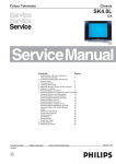
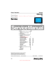
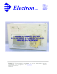
TV4K-NICAM / A2 STEREO
COLOUR TELEVISION RECEIVER
SERVICE MANUAL
SECIFICATIONS
z
SYSTEM
z
z
z
z
z
POWER INPUT
POWER CONSUMPTION
AERIAL IMPEDANCE
TUNER
RECEICING CHANNELS
z
z
z
z
z
PROGRAMME
PICTURE TUBE
SOUND OUTPUT
SPEAKER
AV JACKS
PAL/SECAM,B/G,D/K, I
GERMAN STEREO,NICAM
AC 170-260v(50/60Hz)
100W
75OHM UNVALANCED
VOLTAGE SYNTHESIZER TUNING
VHF-L E2-S10
VHF-H E5-S41
UHF E21-E69
MAX.99 PROGRAM MEMORIES
28”,110°
5W X2
8W 8 OHM ×2
AV SCART ×1
FULL SCART ×1
CAUTION: Before servicing the chassis, read the “Safely Precaution”.
“X -Ray radiation Precaution” and “Product Safety Notice” on Page 2 of
this manual.
X-RAY RADIATION PRECAUTION
1. Excessive high voltage can produce potentially hazardous X-RAY RADIATION. To
Avoid such hazards the high voltage must not be specified limit. The normal value of
the high voltage of this receiver is App. 28.5KV at zero beam current (minimum
brightness) under 230V AC power source. The high voltage must not under any
circumstances exceed 30KV.
2. Each time a receiver requires servicing the high voltage should be checked following
the HIGH VOLTAGE CHECK procedure in this manual. It is recommended the
reading of the high voltage be recorded as a part of the service record. It is
important to use an accurate and reliable high voltage meter.
3. The primary source of X -RAY RADIATION in this TV receiver is the picture tube. For
continued X-RAY RADIATION protection, the replacement tube must be exactly the
same type tube as used in this TV receiver.
4. Some parts in this receiver have special safety-related characteristics for X-RAY
RADIATION protection. For continued safety, parts replacement should be
undertaken only after referring the PRODUCT SAFETY NOTICE below.
SAFETY PRECAUTION
WARNING: Service should not be attempted by anyone unfamiliar with the necessary
Precautions on this receiver.
The following are the necessary precautions to be observed before servicing this
chassis.
1. Since the power supply circuit of this receiver is directly connected to the AC
power line. An isolation transformer should be used during any dynamic service to
avoid possible shock hazard.
2. Always discharge the picture tube anode to the CRT conductive coating before
handling the picture tube. The picture tube is highly evacuated and if broken, glass
fragments will be violently expelled. Use shatterproof goggles and keep picture tube
away from the unprotected body while handling.
3. When replacing a chassis in the cabinet, always be certain that all the protective
devices are put back in place, such as: nonmetallic control; knobs, insulating covers,
shields, isolation resistor-capacitor, network, etc.
4. When replacing parts or circuit boards, disconnect the power cord.
5. When replacing a high voltage resistor (metal oxide resistor) on circuit hoard,
keep the resistor 10mm(1/2 in.) away from circuit board.
6. Connection wires must be kept away from components with high voltage or high
temperature.
7. If any fuse in this TV receiver is blown, replace it with the FUSE specified in the
chassis parts list.
8. The receiver is designed to operate with 230V(50Hz) AC mains.
PRODUCT SAFERY NOTICE
Many electrical and mechanical parts in this chassis have special safety-related
characteristics are often passed unnoticed by a visual inspection and the X-RAY
RADIATON protection afforded by them cannot necessarily be obtained by using
replacement components rated for higher voltage. The use of substitute replacement
parts that do not have the same safety characteristics as specified in the parts list may
create shock, fire, X-RAY RADIATION or other hazards.
GENERAL ADJUSTMENT
AUTOMATIC DEGAUSSING
An automatic degaussing coil is attached around the picture tube, degaussing the tube
properly in about one second after the set is switched on. If the receiver is moved or
faced on a different direction, the power must be switched off at least 15 minutes in
order that the automatic degaussing circuit operated properly. External is necessary if
the automatic degassing proves ineffective when the set is moved.
B+ ADJUSTMENT
CAUTION: To avoid X-ray hazards, B+ voltage must be set in the scale of 140V+/0.5V.
1.
2.
3.
4.
5.
Make sure the AC power supply is 230V, 50Hz.
Switch on the TV receiver, tune in an active channel.
Measure the voltage between C641 on Main P.C. Board DC voltmeter.
Set contrast, brightness, color to maximum.
Adjust VR631 on Main P. C. Board for B+140V+/-0.5V voltage reading.
HIGH VOLTAGE CHECK
CAUTION: There is no high voltage adjustment in this chassis, B+140V voltage
directly relates to the high voltage. The high voltage does not exceed 30KV under any
conditions.
1. Connect an accurate high voltage meter to the second cap of the picture tube.
2. Turn on the receiver, set brightness and contrast to minimum (Zero beam current).
3. Make sure the high voltage does not exceed 30KV.
4. NO matter whether the luminance, contrast and chrominance controls are set to
maximum or minimum, the high voltage must be kept under 30KV.
FOCUSING
Receive a TV test pattern signal; adjust controls for optimum picture. Adjust Focus
Control for a well-defined, sharpest display in the center area of the screen.
ADJUSTMENT AND SERVICING THE VHASSIS
SERVICE MODE
To enter the service mode, a special remote control which contains an additional
SERVICE key must be used to setup the chassis in producing. See the illustration.
Press the ‘SERVICE’ key on remote control, TV will display service menu as following
table 1. To select the parameter requiring adjustment, use the ‘P+/P-’ keys. To adjust
the selected parameter, use the ‘V+/V-’ keys. To quit the service mode, press the ‘P.P.’
key on remote control when in the service mode.
Table 1
Parameter
Red Gain
DC Red
Green Gain
DC Green
Blue Gain
DC Blue
Apr Threshold
Logo
Value
45
063
45
063
45
063
15
6------------
Fix value
Fix value
Fix value
Fix value
Fix value
Fix value
Fix value
Fix value
To enter the table 2, press the ‘OK’ key for the first time on the remote control while in
above service mode.
Table 2
Service V3.0
Parameter
Val
ue
Tuner AGC
22
H position
32
VPOS 50
10
VPOS 60
10
VAMP 50
47
VAMP 60
52
Bright max
63
Bright min
00
Sub Tint
32
VCO Coarse
05
VCO Fine
063
VCO Coarse L1 05
VCO Fine L1
080
Fix value
Fix value
adjusted
not adjusted
not adjusted
not adjusted
not adjusted
Fix value
Fix value
Fix value
Fix value
056-066
France
France
To enter the table 3, press the ‘OK’ key for
the second time on the remote control
while in above service mode.
Table 3
STV9306
SAW50
SAW60
SH
SC
CC
EW VDC
EW AMP
EW SHAPE
EW TRAP
58
61
22
05
10
05
13
00
18
To enter the table 4, press the ‘OK’ key for
the third time on the remote control while in
above service mode.
Table 4
Design
Parameter
AGC gain
Option 1
Option 2
Option 3
Option 4
Option 5
ST Ttext
Value
00
50
00
07
27
00
00
1
2
3
4
5
6
7
8
9
-/-ñ /¢
¢
ò
H POS OSD
V POS OSD
H POS TXT
V POS TXT
001
01
066
04
OPTION1:
B5=P/N/S Crystals application (0=2 crystals, 1=1 crystal)
B4=Cutoff Loop (0= OFF, 1=ON)
B3=Safety_Reset (0=Active, 1=non)
B2=Super Tuner (0=OFF, 1=ON)
B1=Sound Demodulation (0= Intercarrier/MONO, 1=QSS/NICAM)
B0=Logo Display (0=OFF, 1=ON)
OPTION2: (It’s better to keep the default setting option2=0)
B5=Half_Contrast (0=OFF, 1=ON)
B4=Color 6db (0=OFF, 1=ON)
B3=APR Feature (0=ON, 1=OFF)
B2=Black Stretch (0=ON, 1=OFF)
B1=Auto Flesh (0=ON, 1=OFF)
B0=Coring (0=ON, 1=OFF)
OPTION3:
B5=AVL (0=OFF, 1=ON)
B4=PIF Over modulation (0=OFF, 1=ON)
B3=Market_France-SECAM L/L’ (0=OFF, 1=ON)
B2=Manual/Auto Cutoff (0=Manual, 1=Auto Cutoff)
B1=Mute pin Low/High To control the speaker (0=Low, 1=High)
B0=TDA7449/TDA7439 (0=TDA7449, 1=TDA7439)
OPTION4:
B4=SCART2 (0=OFF, 1=ON)
B3=RGB (0=OFF, 1=ON)
B2=SVHS (0=OFF, 1=ON)
B1=AV2 (0=OFF, 1=ON)
B0=AV1 (0=OFF, 1=ON)
OPTION5 and ST Ttext is for teletext setting only. It normally could not be changed. If
it’s necessary to adjust the OPTION 5, please read the following information before
adjustment.
A. For CPUs with English, French, German, Polish or English, French, German, Turkish,
Please refer to the setting as below.
1. If OPTION 5 = 00, then the TEXT languages like "ENGLISH, FRENCH, SWEDISH,
TURKISH, GERMAN, PORTUGUESE, ITALIAN, RUMANIAN " can be decoded.
2. If OPTION 5 = 02, then the TEXT languages like "POLISH, FRENCH, ESTONIAN,
CZECH, GERMAN, SERBIAN, LETTISH, RUMANIAN " can be decoded.
3. If OPTION 5 = 04, then the TEXT languages like "ENGLISH, FRENCH, SWEDISH,
CZECH, GERMAN, PORTUGUESE, LETTISH, RUMANIAN " can be decoded.
4. If OPTION 5 = 06, then the TEXT languages ENGLISH, FRENCH, SWEDISH, TURKISH,
GERMAN, PORTUGUESE, LETTISH, RUMANIAN can be decoded.
B. For coming new OTP/CPU with English, Russian, Czech, Polish, the setting of the OPTION
5 will be changed as below.
1. If OPTION 5 = 00, then the TEXT languages like "ENGLISH, FRENCH, SWEDISH,
CZECH, GERMAN, PORTUGUESE, ITALIAN, RUMANIAN " can be decoded.
2. If OPTION 5 = 02, then the TEXT languages like "ENGLISH, RUSSIAN, SWEDISH,
TURKISH, GERMAN, PORTUGUESE, ITALIAN, RUMANIAN " can be decoded.
3. If OPTION 5 = 04, then the TEXT languages like "POLISH, RUSSIAN, SWEDISH,
CZECH, GERMAN, SERBIAN, ITALIAN, RUMANIAN " can be decoded.
4. If OPTION 5 = 06, then the TEXT languages like "POLISH, RUSSIAN, SWEDISH,
CZECH, GERMAN, PORTUGUESE, ITALIAN, RUMANIAN can be decoded.
Normally, it is supposed not to set OPTION 5 = 01. If you set the OPTION 5 = 01, then the font
can be switched by press key MENU on remote control in TEXT mode for TV4K. If you set
OPTION 5 = 00, 02, 04, 06, then there is no any activity while press MENU in TEXT mode.
Please check.
A.F.C. ADJUSTMENT
Removing any R.F. signal source and prevent any stray signal source from entering
the tuner by shorting the tuner input inner contact to the out screen.
Inject the 38.9 MHZ carrier into the tuner IF output pin (pin 11).Select the parameter
‘VCO Coarse’ in the service mode (Table 2).The ‘VCO Status…’will appear on the
screen. Then press the ‘AV’ key on remote control, the CPU will adjust automatically
until the ‘VCO Status OK’ appears on the screen. If this can not be achieved, adjust
the T201 first and then press the ‘AV’ key on remote control, the CPU will adjust
automatically once again until the ‘VCO Status OK’ appears on the screen.
GEOMETRY
To adjust the picture position and vertical size, select the appropriate parameter in the service
mode and adjust as necessary.
Remote control
35
DIRECTIVTY
6m(MIN)
36
DIRECTIVTY
30°FROM LIGHT AXIS 5m(MIN)
8m(NOR
)
7m(NOR
)
OK
OK
C107
CQ19
47P
RQ05
560
SIF
6.5M
LQ01
10uH
17
15
BSW1
B
42
D012
D013
1N4148
1N4148
G
VSYNC
R
HSYNC
R090
41
CF103
5.5M
R014
19
100
R015
20
FB
AVDD1
21
SDA
PXFM
SCL
JTRETO
VDD
GND
R039
C035
5K6
4n7
38
22
R011
5.6K
R019
6.8K
23
24
25
+5V
C012
0.1u
C013 22P
C606 D606
C033
0.1u
37
D603 C603
Y/CVBSIN3
D604 C604
R622
D614
15K
1N4148
R602
3R9/5W
C036
22P
36
JTDO
AGND
WSCF
TELETEXT
C613
4700P
0.22U/250V
R611
Q611
5K6
WSCR
WSS
35
34
33
C019
470n
C021 82P
26
R018
5.6K
AVDD3
JTMS
TEST0
AVDD2
MCFM
CVBSO
CVBS OUT2
R041
32
10
C022
31
R043
10
28
JTCK
ST92195PLSH
TXCF
30
29
R021
15K
C023
C034
10u
2n2
XS600
C601A
104
27
+5V
Bo
31
trf1062
30
D619
1015 MTZ11C
R623
2K7
C615
0.01
ES1
47
C125 1u
C153
C152
C151
0.1u
R128
330K
0.1u
0.1u
FBI
R402
75
R401
75
R154
75
C327
47P
R615
22K
S600
F601
T3.15Al250V
2 C671
7805
3
33V
9
C631
470P
C629
2200P/400V
R639
22K
VR631
2K
C1815
R636
6K8
R689
R637 22K
R688
Q652
+5V
2SA1015Y
BCLP
RESET
1K
R653
10K
C659
10K
Q685
C1815
D641
6V2
Q686
A1015
D685
6V2
C685
1UF
C650
10UF/16V
Q682
HD
R686
150K
ON/OFF
R629
8.2M/1W
1K
1K
BREATH
SENS1
EWSENS
EWOUT
VOPS
OUT
GND
SENS2
HEAT
BCLV
T802
D805
D134
1N4148
HV
7
3
R802
4
1R/0.5W
FV
6
8K2/2W
8K2/2W
R801
8K2/2W
1R/2W
SV
2
9
C808
C812A
100u/160V
10
0.1U/250V
Q802 L819
D2539/2SC5296
0.2UH
1
8
L801
R813 0.1u Q801
100
D810
IN4148
50Hz
T801
C318
XS600A
AC230V
+180V
C802
10U/250V
D801
1N4937
R808
R808A
R687
560K
1R1/2W
C146
4.7u/50V
+26V
C1815
180K
C801 220P/500V
L802A
100UH
+140V
R809
R635
150K
HCOIL
1K
R804
3R3
33V
R638
68K
R807
1K
XS803
R814
1
1
R843
10K
C812
1000u
470UF/16V
+140V
RU4AM
35UH
FR104
+5VA
D631
13
C839
+8V
C662
0.1u
R650 10UF
10K R650
D650
3V9
R640
15K/2W
L804
C809
0.27U/400V
D813
470UF/16V
C655
470UF/16V
VCOIL
R336
470
0.1u
3
1
C658
100UF/16V 0.1u
C654
2 C652
0.1u
D626
470P
7808
C690
0.1u
C661
R685
C637
16
100UF/16V
R670A
IC605
32V/1w
C807A
56P
C675
2 C674
IC604
7805
3
D311
R801A
0.1u
22/5W
10K
C641
100UF/160V
L801
3
0.1u
R655
2K2
R610
0.33/1W
2
C657
7812
C651
D635
RU4YX C635
1000u/35V
17
4.7/2W
C309
4.7UF/160V
D108
1N4148
IC602
22n
R329
SC
1
C319
C809A C314
0.027U/400V
1U/250V
C656
R314 R320
10K 2.2K
2200u
L803
1
2200u/25V
9
3
D302
1N4004
R331
10UH
C133
470u
C312
1n
R323
+12V
IC606
100
R312 R313
100K 15K
100u/35V
1K
C813
0.1u
R311
220K
R324
R335
100 68K
R322
C306
C302
330n
R317
VS
R153
75
L112
R404
470 0.1u
1
R626
2K2
C301
C328
100n
47P
10
C634
390P
8
Q612
2SC3807
R504
R505
R302 100
24V
C653
100UF
2SC4429/5299
FLYBACK
SDA
RI
GI
R156 R155
75
75
IC301
STV9306
R301 100
SCL
VCC
28
SYNC
27
Q401
C1815
15
2
R617
1K
C510
0.01/500V
NC
FBEXT
NC
26
CHOLD
25
SDA
24
NC
NC
APR
23
BI
D634
RU4YX
Q613
0.1u
D616
1S1555
C504
10u
82
VS-1
CRAMP
22
C401
1u
R123
1K
1
5
R624
2
39
C509
2200p/1K6V
5
29
SCL
21
C117
1u
Q683
B892
T611
C616
1000/2KV
13
2
BCLV
CHR
BS
20
2
R625
6.8
R620A
120K
C602
L002
C003 4n7
D605
T601
C004
C005 220n
R620
120K
C605
R049
5.1K
39
R506
1K
CVBS OUT1
Go
32
Icath
BOSD
ROSD
FBOSD
CVBSIN2
19
C402
1u
TLP621
4
VS-1
SC
100
220P
C607
220u/400V
T602
14
+12V
GND2
18
C119
2
18
1K
SCL
ERC05-10B
22K
40
1K
R034
D603-606
C603-606
1000P/1KV
D503
IN4148
R515
2K7
CRT BOARD
R124
CF102
N615
3
C508
470P
2
BSW1
15
R521
R131
470
BOUT
33
ROUT
R028 1K
34
SAW1
43
STV5112
1
R517
4.7K
D505
IS4148
XP504
C505
10UF
1UF/50V
1K
R033
OSD FB
BSW2
NC
R520
10K
XS804
+12V
R132
470
R133
470
GOUT
R027 1K
35
GOSD
R026 1K
36
C118
1u
SAW2
44
1K
22K
R405
Ro
CT
OSD B
OSD G
OSD R
R025 2K7
37
XTAL3/BTUN
XTAL2
17
L110
10UH
45
38
CVBSIN1
XTAL1
PIFLC2
16
L101
R119
220
L103
8.2uH
C121
47u
10n
47
46
27K
R136
CLPF
PIFLC1 X1/VAMP/CHROUT
15
Vcc2
10K
R142
GND1
CVBSOUT1
EXTAUDIO
INTCVBSOUT
14
39
1K
CQ12
56p
R513
2K7
0.68R
3
IN4148
R512
220
1N4937
X001
4M
C452
S-SW2
1n C450
1n
470UF
C3415
R3417
OSD FB
8V
Vcc1
VccIF
C154
1u
13
C103
C108
1n
K2955M
C015
39PF
C139 10n
4.7U
BCL/SAF
VERT
AM/FMOUT
12
42
5
2
C014
39PF
CVBS OUT2
VS
C141
IFPLL
GND IF
TUNERAGCOUT
11
C106
0.33u
1
C002
0.1u
HOUT
SLPF
PIFIN2
R121
150
0.022u
68
R408
560
C805
33K
BCLP
D107 1N4148
HD
SC
SCL
SCL
Vcc D
C124
4
10
21
20
19
18
17
16
15
14
13
12
11
10
9
8
7
6
5
4
3
2
1
21
20
19
18
17
16
15
14
13
12
11
10
9
8
7
6
5
4
3
2
1
C451
8OHM/8W
D3403
4148
+9V
+8V
+5V
MUTE
17
16
MXOL INL
15
18
INR
LIN3
LIN2
9
43
R135
1K
R134
47k
Q631
16
OSD R
10UH
8
44
X102
4.43M
41
40
C645
1K
R031
10UH
SAW101
VT
+5V
R029
OSD G
R009
4.7K
7
0.015u
14
OSD B
C008
0.1u
33K
C001
0.1u
48
6
C109
1u
10u
R004
50
49
5
D501
7
R503 R509
1K2 82K
220P/500V
SAW-SW1
NC
R001
33K
33K
R003
4
C123
VO1
D808
1N4004
NC
NC
3
C122
1u
R407
C801A
100P/50V
2SC2482
R817
SAW-SW2
NC
51
2
C145
45
C129
0.1u
C127 C126
0.1u
0.1u
BSW2
ST24C01
D004
1N4148
NC
R002
10K
1
33V
46
C506
470P
R517
220
4.7UH
R149
10K
L818
0.6UH
C816
330P/500V
R310
22K
C807
0.039U/63V
R315 15K
1K5
13
VOL PWM
S0
52
R012
0.1u
C128
0.1u
R129
68K
C617
IC001
E0 VCC
E1
WC
E2 SCL
GND SDA
12
C011
0.1u
S1
R037
39K Q001
1815
R075
680
R074
470
47
V501
A48QA220X
9
6
330P/500V C801B
SCL
+5V
11
8OHM/8W
4
Bo
+12V
R007
4K7
NC
54
C031
47PF
53
R073
270
48
XS601
6K8
S-SW1
R072
120
55
49
IC003
STV2246C/48C
R619
SDA
10
OSC
P+
D617
R060
S-SW2
P-
50
C614
S-SW1
9
OSC
V+
0.22uF/400V
S-SW2
R016
6K8
C408
0.1u
R514
2K7
R502 R508
1K2 82K
1
R005
4K7 8
6K8
R020
C407
10UF
10
R516
4.7K
R519
47K
XP501
D502
IN4148
470P
R518
4.7K
R406
68
Q402 C1815
C507
11
CN101
Go
RO
LO
C439
4.7uF
12
R511
220
Ro
R433
560
VIN3
R036
ON/OFF
STDBY LED
ON/OFF
C444
4.7uF
VIN2
7
4148
8V
MUTE
3K3
BI
3
HEAT
CVBS OUT1
6
RESET
MUTE STDBY LED
NC
D3402
C138 C137 C161
4700P 0.1u 18PF
0.1u
5
D3404
4148
R450 R451
22K
22K
R434
560
IC501
Q501
A1015
GND
5V(A)
RED D001A
HFT505M
GREEN
CN001/1 R015
1K
VT
NC
V-
51
1n
180V
C131
470u
R143
2.2K
AGC
4
SW6
R146
2.2K
PIFIN1
C040
0.1u
R015A
1K
SW5
52
Vref IF
3
NC
RESET
56
SW4
RT601
10UF
2
KB INPUT
IRIN
SW3
53
GND D
56
R145
8.2K
22K
RIN2
LIN2
CT
SP601
1N4148
R455
VO1
S-SW1
RI
GI
C3413 C3402
100n 0.39u
D461
10K
R3431
47K
C453 R454
22K
1n
VIN3
L113
10UH
R137
15K
C134
10n
55
54
C600A
10UF
C009
100uF
L001
C135
1u
10n
0.22u/250V
CN001/2
C041
+5V
C105
AGCSIFCAP
4.7K R23
CN001/3
1
C1815
1N4148
R144
56K
R138
C142 2.2K
2.2u
R139
2.2K
C132
470u
FMCAP
R079
10
C067
6K8
C143
4n7
AUDIOOUT
2SA1015Y
R116
100
10K
GND
VCC
R076
R147
100
3
1K
IC011
+5V
4
R071
CN001/4
+5V
+8V
2
R148
100
10UH
SIFIN2
1N4148
BH
BL
10K
5
MZ72-18
10K
L111
1
C238
10u
5K6
R231 5K6
OUT
BSW2
R255
4K7
CN001/5
BSW1 R232
Q205
R234
R233
SAW102
K9650M
SIFIN1
R237
D462
C486
D465
1N4148 470u
R484
22K
LFB/SSC
47u
10UH
C104
10n
C236
10u
2SA1015Y
2SA1015Y
Q206
D209
BU
1N4148
D211
R101
27K
D210
1N4148
C235
C233
1n
AGC
C240
10u Q204
14
1u
C437
L202
4K7
0.1u
22u
C3407
3.3UF
R3416
100
R3430
Q3404
R452
60MA
11
R102
C111
6
1K
Q464
A1015
R3415
4R7
RI
LO RO
FBI
1
2
SW LI
BI
GI
R501 R507
1K2 82K
R453
22K
R3414
4R7
R3412
100 C3411
100n
FBI
RI
VI
VO
RIN1
C3416
470UF
10
D463 1N4148
+5V
C239
LIN4 MXOR
13
20
LIN2 MINR 19
11
12
21
LIN1 MOR
22
BIR
RIN1
10
23
9
RIN3
BIL
8
RIN2 BOR
24
RIN4 BOL
7
26
27
25
MOL
LOT
6
ROT
MIL
AGND TRL
4
5
29
28
VS
TRR
CRF DGND
3
30
22
23
reset
cap7
arout
avcc
24
25
sd
20
21
+8V
1u
4
IC3401
TDA7263M 3.3UF
C3408
R3420
680
C3421
2200P
SDA
10
1K
RI
LO RO
LIN1
C3409
2200P
SDA
9
C436
9 8
SW LI
BI
GI
SCART2
VIN2
SP602
R3413 C3401
3K3
0.39u
0.01u
5
C3420
0.1u R3409 1K
AGCPIFCAP
8
VT
R008
4.7K
SDA
RQ10
L401 1K
10UH
10UF
5V(A)
7
R3411
0.1u
CQ26 RQ11
LIN1
VCC
6
CQ02
3
C3406
C443
1u
RQ12 1K
D3401
4148
2.2u
10UF 1K
CQ27
RQ13
CQ01
10n
CQ04
1u
CQ05
1u
+26V
1R/2W
FBI
RI
VI
VO
SCART1
R810A
C3417
1000UF/35V C3418
C433
C3419
100UF/35V
1u
LO R434A 560
BL
5
C432
C442
0.1u
RO R433A 560
BH
4
C435
10u
RIN1
BU
3
R424
2.7K
5.6n 5.6n 18n 22n 100n 100n 100n 100n 22n 18n 2.2u
RIN2
VT
2
R423
5.6K
CRITICAL PARTS
C426C421 C427C422C428 C423C424C429 C425C431
C434
100UF
IF
AGC
1
CQ03
R422
5.6K
C417
RQ02
39
10u
1n
CQ06
10u
TU201
alout
19
17
18
27
26
srout
ws
sck
28
16 slout
nc
29
cap1
15
CQ07
10p
CQ09
10n
SIF
nc
30
13
14
arin
cap2
nc
dcl
alin
12
11
nc
31
32
33
xout
gnd4
xin
10
slin
srin
nu
cap8
9
min
8
7
gnd1
34
35
36
sda
37
38
10n
CQ24 5
6
gnd3
mout
nc
scl
39
40
reg
cap3
cap6
av5b
3
sif
2
4
42
gnd2
dvdd5 41
IC400
cap5
1
CQ10
CQ08
220n
10u
1
STV8203
20k
NOTE: SUBJECT TO CHANGE WITHOUT NOTICE
R421
2.7K
2
100n
RQ03
220K
CQ16
10p
RQ04
CQ13
10u
SCL
CQ17
10p
10n
IC401
TDA7439
XQ01 27M
CQ18
103
CQ11
10n
100
10UH
CQ15
CQ14
1015
QQ01
R426 100 SCL
R429
LQ06
av5a
CQ20
10u
RQ08
100
SDA
RQ07
100
LQ03
10UH
SDA
+8V
SDA
SCL
+5VA
CTV2811N-JL TXT/NICAM SCHEMATIC DIAGRAM
C810
220P/2KV
C843
5n6/1600V
C842
8n2/1600V
C811
27n/400V
R341
D802
RS3FS
D803
1N4937
+12V
10K