1
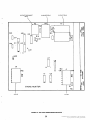
PC BOARD VR21
8
8
1 2
TBI
3
4
5
6
7
8
3
1
0
1
1
I
~
VRZl
COMMUTATING
REACTORS (L21 & L22)
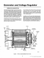
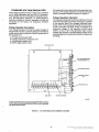
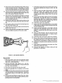
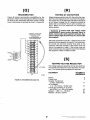
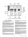
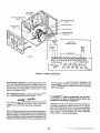
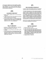
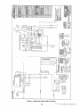
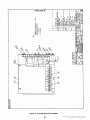
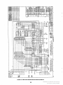
FIGURE 6. VOLTAGE REGULATOR ASSEMBLY (305-0695-02)
Generator stator current is also supplied to the commutating reactors L21 and L22 (three phase only).
These reactors are used to produce a uniform AC
wave. The output terminals of the reactors supply AC
current to the power circuit on the regulator circuit
board (VR21).
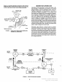
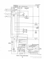
The power circuit primarily consists of a power transistor (Q4), pulse transformer; (TI), and rectifying
diodes. When the power transistor is turned on, AC
current from the commutating reactors is rectified to
DC and supplied to the exciter field. The current flow
stops when the power transistor is turned off. The
voltage of the DC output is directly proportional to'
the on-off switching frequency of the power transis-
tor. An increase or decrease in the switching frequency causes a corresponding increase or decrease
in the DC voltage produced. The nominal switching
frequency is approximately 125 Hz.
'
The pulse transformer T1 is used to trigger the firing
of the power transistor. Triggering is accomplished
by reverse saturating the transformer and then releasing it. This initiates conduction in the power transistor which remains on until the transformer saturates
in the forward direction. Using the pulse transformer
to trigger the power transistor helps isolate the power
circuit from the voltage regulating circuit.
'
8
Redistribution or publication of this document,
by any means, is strictly prohibited.