1
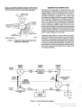
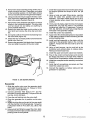
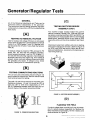
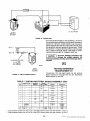
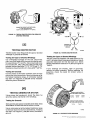
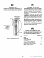
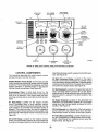
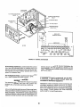
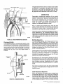
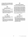
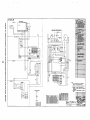
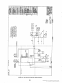
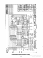
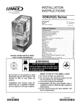
FREQUENCY
METER
DUAL RANGE
AC AMMETER
\
\
DUAL RANGE
AC VOLTMETER
1
\
N
c
-
INDICATOR
LAMPS
START
VOLTAGE
ADJUST
RHEOSTAT
88
0
PAE
HEAT
RESET
LAUPTEST
PHASE
SELECTOR
SWITCH
AMMETER/
VOLTMETER
:ALE INDlCATllVG
LIGHTS
......
I
/
DC
AMMETER
OIL PRESSURE
GAUGE
.
I
WATER
TEMPERATURE
GAUGE
^
SC-1302-1
FIGURE 29. NINE LIGHT CONTROL PANEL WITH OPTIONAL AC METERS '.
CONTROL COMPONENTS
Start/Stop/Remote switch is placed in the Start position. See Figure 30.
The following describes the basic engine control
components and how they function.
K3 Sfarf Disconnect Relay: Located on the engine
monitor circuit board. Energized by voltage output
from the battery charging alternator. Disconnectsthe
cranking circuit and turns on thegreen Run indicator
lamp when the engine starts. See Figure 30.
Engine Monitor Circuit Board: A solid state printed
circuit board that monitors all engine control system
functions. This includes starting, stopping, and fault
system operation. A terminal board is included for
making remote connections. See Figure 30.
K1 Start Solenoid: Located on the generator set skid
base. Connects battery positive (B+)to the starter
solenoid and K2 heater solenoid when the Start/Stop/
Remote switch is placed in the Start position. See
Figure 31.
Overcranking Timer: A solid state circuit on the
engine monitor circuit board that limits cranking time
from 45 to 75 seconds. If the engine does not start,
cranking will stop and an oyercrank fault will be indicated.
K2 Heater Solenoid; Located on the generator set
skid base. Connects battery positive (B+)to the glow
plugs when the Pre-heat switch is placed in the On
position. See Figure 31.
K1 Fault Relay: Located on the engine monitor
circuit. Energized when a fault condition occurs.
Turns off the engine and prevents restarting until the
fault condition is corrected and the Reset switch is
pressed. This relay can also be used to operate a
remote DC alarm (5 amp maximum) connected to the
fault terminal of the engine monitor circuit board. See
Figure 30.
K3 FuelSolenoid:An integral part of the fuel injection .
pump. Opens the fuel control valve when the Start/
Stop/Remote switch is placed in the Start position. K11 Start Disconnect Relay: Located inside the control box. Energized by a voltage output from the generator. Disconnects the cranking circuit when the
engine starts. See Figure 30.
K2 On/Off Relay: Located on the engine monitor
board. Connects battery positive (B+)to the electrical
circuits on the engine monitor circuit board when the
35
Redistribution or publication of this document,
by any means, is strictly prohibited.