1
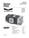
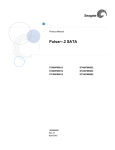
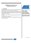
Ninja ZX-6RR 2005 Ninja ZX-6RR Racing Kit Manual This manual contains only the information of the racing kit parts. Refer to the base manual listed below for information of the original model. Base Manual Part Number Ninja ZX-6RR Motorcycle Service Manual 99924-1346-01 © 2005 Kawasaki Heavy Industries, Ltd. First Edition (1): Jan. 14, 2005 Congratulation on your purchase of racing kit parts for the 2005 Ninja ZX-6RR. IMPORTANT This manual provides how to install racing kit parts for the 2005 Ninja ZX-6RR and how to tune up basically. As for the basic knowledge, refer to the base Service Manual for the Ninja ZX-6RR (P/No. 99924-1346-01). When you participate in a race, it is necessary to modify the machine for the regulation. So we want you to ask for the tuning up shop. WARNING AFTER ANY MODIFICATION TO TUNE THE VEHICLE TO A COMPETITION MACHINE, IT SHOULD NOT BE USED ON PUBLIC STREETS, ROADS OR HIGHWAYS. THE USE OF THIS VEHICLE SHOULD BE LIMITED TO PARTICIPATION IN SANCTIONED COMPETITION EVENTS UPON A CLOSED COURSE. CAUTION When operating the engine, be careful not to trouble persons with noise. Do not turn the engine with loud engine and exhaust noise. DISCLAIMER OF WARRANTY ON OPTIONAL TUNING PARTS FOR RACING ARE NO WARRANTIES EXPRESSED OR IMPLIED. BASIC WORKS IN INSTALLING KIT PARTS We are going to make up the original Ninja ZX-6RR for the racing machine. We recommend that the rider himself should do the basic works, removing parts or installing parts etc., given advices by the tuning shop. In a race, although trouble will be apt to happen, if you participate in basic works, you can discriminate cause of trouble, so you can return the race soon. But concerning difficult technical works, you should as tuning shop. 1 Table of Contents General Specifications ........................................................................................................3 Racing Kit Service Data ....................................................................................................5 Periodic Maintenance Chart...............................................................................................5 Preparation ..........................................................................................................................7 Before Installing ................................................................................................................7 Racing Kit Parts .................................................................................................................7 Engine Parts Installation ....................................................................................................7 Air Intake Parts .................................................................................................................7 Cylinder Head ...................................................................................................................9 Camshaft Chain Tensioner ............................................................................................. 11 Camshafts, Sprockets.....................................................................................................12 Valve Springs..................................................................................................................12 Cylinder Compression ....................................................................................................13 Crankshaft Main Journal and Con-rod Big End Bushings...............................................15 Connecting Rod Bolts .....................................................................................................15 Clutch Adjustment (Back-Torque Limiter Setting) ...........................................................16 Transmission ..................................................................................................................20 Transmission Shimming..................................................................................................20 Generator (Kit) ................................................................................................................22 Generator Cover (Kit) .....................................................................................................22 Cover Gaskets ................................................................................................................22 Ducts (Air Funnels) .........................................................................................................22 Muffler.............................................................................................................................22 Water Temperature Sensor.............................................................................................22 Radiator (Kit) ..................................................................................................................22 Radiator Installation ........................................................................................................23 Radiator Installation ........................................................................................................24 Reserve Tank Installation................................................................................................25 Frame Parts Installation ...................................................................................................26 Throttle Parts (Kit)...........................................................................................................26 Final Drive Parts (Kit)......................................................................................................27 Brake Pads (Kit)..............................................................................................................28 Steering Damper (Kit) .....................................................................................................28 Seat Height Adjustment ..................................................................................................29 Front Fork Springs (Kit) ..................................................................................................31 Electric Parts Installation..................................................................................................33 Battery ............................................................................................................................33 Main Harness and Sub Harness (Kit) .............................................................................33 Meter (Kit) Installation.....................................................................................................33 Wiring Routing ................................................................................................................36 Wiring Diagram (with Kit Meter)......................................................................................42 Wiring Diagram (with Original Meter Assembly) ............................................................44 Wiring Diagram (Sub Harness) .......................................................................................46 2 General Specifications Item 2005 Ninja ZX-6RR Racing Engine: Ignition timing 12.5°BTDC @1 300 r/min (rpm) Fuel (Recommended) Racing gasoline Engine oil (Recommended): Racing oil Level Between upper and lower levels of oil level gauge. Drive Train: Primary drive reduction ratio 1.891 (87/46) Transmission Gear Table 1st 2nd 3rd 4th 5th 6th In Out Teeth (Out/In) Gear Ratio In Out Teeth (Out/In) Gear Ratio In Out Teeth (Out/In) Gear Ratio In Out Teeth (Out/In) Gear Ratio In Out Teeth (Out/In) Gear Ratio In Out Teeth (Out/In) Gear Ratio Original Type A Type B Type C 13127-0033 13262-0297 39/16 2.437 13260-1987 13260-1992 37/18 2.055 13262-0143 13260-1993 31/18 1.722 13262-0143 13262-0044 33/22 1.500 13262-0144 13262-0150 28/21 1.333 13262-0188 13262-0187 27/22 1.227 13127-0033 13260-1619 * 39/16 2.437 23262-0091 13262-0092 37/19 1.947 see note 13262-0038 35/21 1.666 see note 13260-1994 29/20 1.450 13127-0034 13260-1543 35/14 2.500 13260-1987 13260-1992 Original 2.055 see note 13260-1993 Original 1.722 see note 13262-0044 Original 1.500 13262-0144 13262-0047 29/21 1.380 13262-0188 13262-0050 28/22 1.272 13127-00135 13262-0034 40/17 2.352 13262-0035 13262-0036 32/17 1.822 see note 13262-0038 35/22 1.590 see note 13262-0090 29/21 1.380 13262-0110 13260-1995 28/22 1.272 13260-1990 13262-0254 30/26 1.153 Original Original Note: 4th gear type 3rd gear type A B C A 13262-0145 (A-A) 13262-0149 (A-B) 13262-0147 (A-C) B 13262-0109 (B-A) 13262-0143 (B-B) NA (B-C) C 13262-0148 (C-A) NA (C-B) 13262-0146 (C-C) 3 Reduction Ratio 3.0 2.5 STD Type A Type B Type C 2.0 1.5 1.0 1 2 3 4 5 6 Gear Position Number of Grooves 1st 2nd 3rd 4th 5th 6th STD Type A Type B Type C In 4 1 2 3 Out 1 1 2 3 In 1 2 1 3 Out 0 2 0 3 In 0 1 0 2 Out 0 1 0 1 In 3 0 3 0 Out 2 0 2 3 In 3 3 3 2 Out 3 3 2 1 In 3 3 3 2 Out 3 or 1 3 or 1 2 1 *: 1st gear out – STD is interchangeable with type A. 4 Racing Kit Service Data Item Standard Cylinder Head, Valves: Duration: Intake 320° Exhaust 272° Camshaft timing (cam lift center): Intake 105° (ATDC) Exhaust 105° (BTDC) Valve clearance: Intake 0.18 mm Exhaust 0.28 mm Valve to piston clearance: Intake 0.7 mm (Minimum) @12°ATDC Exhaust 1.4 mm (Minimum) @12°BTDC Ignition System: Spark plugs NGK R016-10, R0373A-10 Spark plug tightening torque 13 N·m (1.3 kgf·m, 113 in·lb) These values show the specifications when standard cylinder head and gasket are used. When the clearance between the valve and the piston head is smaller than the minimum specific values, turn the installed position of the camshaft sprocket on the camshaft and change the camshaft timing. Periodic Maintenance Chart The scheduled maintenance must be done in accordance with this chart to keep the motorcycle in good running condition. FREQENCY OPERATION Each Every Every Every Race 3 races 5 races 10 races (300 km) (1 000 km) (1 500 km) (3 000 km) Engine Clutch plate - - check* ● Throttle grip play - - check* ● Spark plug - - clean/gap* ● Engine oil - - change ● Oil filter - - replace ● Valve lapping ● Cylinder head/valve - - decarbonization ● 5 As Required FREQENCY OPERATION Each Every Every Every Race 3 races 5 races 10 races (300 km) (1 000 km) (1 500 km) (3 000 km) Cylinder - - check* ● Piston/cylinder clearance - - check* ● Piston, Piston ring, Piston pin - - replace ● Crankshaft main bearing - - check* ● Connecting rod big end bearing - - check* ● Transmission gear, bearing - - check* ● Engine sprocket - - check* As Required ● Coolant - - change ● Radiator hoses, connections - - check* ● Frame Brake operation - - check* ● Brake pad wear - - check* ● Brake fluid level - - check* ● Brake fluid - - change* year Brake master cylinder cup and dust seal - - replace year Brake caliper piston seal and dust seal - - replace year Brake hose - - replace 2 years Drive chain - - adjust ● Drive chain - - lubricate ● Drive chain wear - - check* ● Drive chain guide - - replace If damaged Front fork - - clean/check* ● Front fork oil - - change First change after 2 races, then every 5 races Nut, bolt, and fastener tightness - - check* ● Fuel system - - clean ● Fuel hose, fuel filter - - replace ● Steering play - - check* ● Steering stem bearing - - grease ● Rear sprocket - - replace ● General lubrication of chassis - - perform ● Wheel bearing (rear) - - grease ● Swingarm pivot, uni-track linkage - - grease ● Swingarm pivot, uni-track linkage - - check* ● *: Replace, add, adjust, clean, or torque if necessary. 6 Preparation Before Installing Modify the parts based on your race regulation. To avoid misuse keep the parts replaced with the kit parts separate. When reusing parts, clean them and check them for damage or deterioration. Main Removal Parts: Lights Rear View Mirrors Side Stand Starter Lockout Switch Remove the side stand switch. When the optional main harness is not used, connect removing Black/Yellow and Green/White Leads directly. Racing Kit Parts Also, we have provided the spare parts, and other optional parts (engine, frame, and electric parts) for racing. So please order each parts referring to the “Racing Kit Parts List” in the back of this manual. Engine Parts Installation Air Intake Parts Remove the air cleaner element or cut the cleaner element off remaining the wire net to reduce the air flow resistance. When removing the air cleaner element, remove the element and relational parts as shown in next page. Remove the tank (16181-0002) to reduce the weight. Plug the holes firmly with a tape. The air pressure in the duct rises during high speed operation because the Ram Air System is used. 7 A. Remove (Wire Net) B. Remove this part and plug the hole. 8 1. Remove the parts. 2. Remove the parts. 3. Plug the holes. Cylinder Head Grind off the stepped portions of the ports and smooth the inside of ports to make intake/exhaust gas flow more smooth. Grind off the stepped portion only at the mating surface between the carburetor holder and the intake port. Do not port it. To extend the intake port, air flow speed will be reduced and the engine performance at the high speed range may be down. Mark the carburetor holders so that they can be installed in their original positions. 9 Grind off and smooth the stepped portions at the mating surface between valve seat and the port. Smooth the inside of the intake port and exhaust port. Chamfer the machining edge of the cylinder head where the valve seat is installed, also smooth the dome of the combustion chamber with the valves installed. Excessive smoothing may reduce the cylinder compression. Use the hand grinder. Use #200 oil stone for eliminating any stepped portions. Use #200 oil stone for smoothing and #300 oil stone for finishing. NOTE These procedures make air resistance less and intake/exhaust gas flow more smooth. However, much more effect can not be expected by excessive grinding and smoothing. It may be done to the extent of getting rid of uneven surfaces. A: Stepped Portions - - -: Combustion Chamber Dome The combustion chambers are modified by cutting work but the edges shown must be hand finished for smooth corners (Round them to about R1). 1. Edges (4) NOTE When grinding the cylinder head bottom surface or using thinner gaskets, adjust the valve timing to keep that the valve to piston clearance is not less than the minimum value (IN: 0.7 mm, EX: 1.4 mm). 10 Camshaft Chain Tensioner Replace the cam chain tensioner with the kit to decrease the flutter of tensioner. Apply the engine oil to the tensioner rod, O-ring and tensioner body, insert them into the tensioner body. Check to see that the tensioner rod turns freely in the body, if not, polish the tensioner rod or fine the female threads in the body with a tap (Diameter × Pitch = 6 mm × 1.0 mm). Install the tensioner on the cylinder block with the tensioner rod is fully pushed back. Turn the tensioner rod in with a screwdriver until it becomes hard to turn. Turn the crankshaft clockwise forcing lightly to the tensioner rod with twisting force to take up any gap and tighten the locknut. NOTE Never forward the tensioner rod forcibly, this will increase mechanical loss of the tensioner and may damage to the chain guide. The cam chain tensioner must be adjusted at every race. 1. 2. 3. 4. 5. Tensioner Tensioner Rod O-ring O-ring Lock nut 11 Camshafts, Sprockets Camshafts, Sprockets: Camshaft Duration Lift Original Camshaft (Intake) 320° 8.7 mm 272° 7.0 mm Original (Exhaust) Camshaft Adjust the valve clearance within the specified value. Intake: 0.11 ~ 0.19 mm, Exhaust: 0.25 ~ 0.31 mm More performance is expected when adjusted from middle value to upper limit between adjustable range. If you can not adjust the valve timing for racing, install the camshaft sprocket to the kit camshaft using the round bolt holes and adjust the cam chain timing according to the Ninja ZX-6RR Service Manual. If you adjust the valve timing, install the sprocket to the camshaft between the adjustable range of the long bolt holes. Tighten the camshaft sprocket bolts to 15 N·m (1.5 kgf·m, 11.0 ft·lb) of torque. Valve Timing (when the round bolt holes are used) Timing (cam lift center) Intake Exhaust Original 105° 105° 103 ~ 107° 103 ~ 107° Race use When grinding the cylinder head bottom surface, grinding the cylinder top surface or using thinner gaskets, be sure the valve to piston clearance especially. When using the sprocket long bolt holes and adjusting the valve timing to be different from the standard timing, check the valve to piston clearance of all cylinders after adjusting the valve clearance correctly. Valve to Piston Clearance (Min.) Intake 0.7 mm Exhaust 1.4 mm If the valve to piston clearance is less than the minimum value, do not start the engine because the valves will touch the piston and the engine may be damaged. Measure the valve to piston clearance at about 12° ATDC (Intake) and 12° BTDC (Exhaust) of crankshaft timing. At this point, the valve to piston clearance will be minimum. Valve Springs The original machine’s valve springs should be used. 12 Cylinder Compression To adjust the cylinder compression, adjust the thickness of the cylinder head gasket and the cylinder base gasket or smooth the cylinder top surface to make the piston squish 0.65 ~ 0.8 mm. Keep the piston squish more than 0.65 mm. Position the piston at Top Dead Center, and put a small piece of modeling clay on the shoulder of the piston. Install the cylinder head gasket and cylinder head, and tighten the head bolts to the specified torque. Remove the cylinder head and measure the thickness of the clay. The thickness of the collapsed clay is the size of the squish. Squish Measurement [1] Front and Rear 0.65 ~ 0.80 mm [2] Left and Right 0.67 ~ 0.85 mm The most preferable squish measurement is [1] 0.65 mm/[2] 0.67 mm. Select proper cylinder head gasket and cylinder base gasket. Note that by grinding the cylinder head surface only left and right squishes become narrower, while by grinding the cylinder top surface or decreasing the gasket-thickness all the squishes become narrower. Cylinder Head Gasket Part No. Thickness Note 11004-0020 0.45 mm KIT 11004-0018 0.60 mm KIT 11004-0036 0.65 mm Original 11004-0019 0.70 mm KIT Part No. Thickness Note 11061-0036 0.15 mm KIT 11061-0033 0.20 mm KIT 11061-0041 0.25 mm Original 11061-0037 0.30 mm KIT Cylinder Base Gasket 13 1. Squish, Front/Rear 2. Squish, Left/Right 14 Crankshaft Main Journal and Con-rod Big End Bushings Crankshaft Main Journal Bushings: Use original bushings. Con-rod Big End Bushings: Use kit bushings (Size colors are same as original). Connecting Rod Bolts Use the original connecting bolts and nuts. The original connecting rod bolt has recesses at both ends to measure its length and determine the bolt stretch. Install the original bolts into the connecting rod. Before every tightening, use a point micrometer to measure the length of the bolts and record the values to find the bolt stretch. Apply a small amount of molybdenum disulfide grease to the threads of bolts. Tighten the big end nuts at the torque of 20 N·m (2.0 kgf·m): reference Check the length of the bolts and find the bolt stretch. Bolt Length after tightening – Bolt Length before tightening = Stretch Bolt Stretch Usable Range: 0.33 ~ 0.38 mm (0.013 ~ 0.015 in.) Turn the big end nuts more until the bolt stretch reaches the usable range. NOTE Replace the original bolts with new ones if they have already been tightened up to usable range 2 times. 15 Clutch Adjustment (Back-Torque Limiter Setting) The Ninja ZX-6RR engine is equipped with the Kawasaki back-torque limiter mechanism in the clutch. The back-torque limiter works to reduce the chance of rear wheel hop caused by engine braking during hard braking and down shifting. The back-torque limiter operating condition can be changed by changing the total thickness of clutch plates and changing the number of leaf springs. Try different settings and select the best. 16 The standard setting of length [A], total thickness of clutch plates shown below, becomes about 38.8 mm (Supposed combination of steel plates is t1.6 with spring × 1 pcs. + 1.6 × 1 pcs. + t2.0 × 5 pcs.). For this setting the effective stroke of clutch spring plate during the back-torque limiter operation is adjusted between 0.45 and 0.75 mm. By increasing the effective stroke the back-torque limiter causes more slip. The effective stroke increases by decreasing the length [A]. The length [A] between 37.6 and 38.8 mm is available by changing the combination of the steel plates. Replace one steel plate with a thinner one and try the setting. If the operation of the back-torque limiter is not enough replace other steel plates one by one. Thickness (mm) Part Number Used Number with spring 13089-0003 1 (first inside use) 1.6 13089-0005 Selection (1 Original) 2.0 13089-0007 Selection (5 Original) * Steel plates of 2004 model’s are available. Thickness (mm) Part Number 1.6 13089-013 2.0 13089-1073 For precise setting the measurement of the effective stroke of clutch spring plate is recommended. • Remove oil from clutch plates. • Hold an extra drive shaft in a vise and install the following clutch parts on the shaft. 17 [A] [B] [C] [D] [E] Spacers Needle Bearing Bushing Clutch Outer Casing Clutch Hub [F] [G] [H] [I] [J] Sub Clutch Hub Friction Plates: 8 pcs. Steel Plates Spring Plate Steel Plate with Spring 18 • Engage the cam followers (Clutch Hub) with the cams (Sub Clutch Hub). • To measure the effective stroke of clutch spring plate, set a dial gauge [A] against the raised center [B] of the clutch spring plate. • Move the clutch housing gear back and forth [C]. The difference between the highest and lowest gauge readings is the amount of the effective stroke of clutch spring plate. [D] Drive Shaft After installing the clutch to the engine, measure and record the depth [B] shown in the figure on page 18. The length from the clutch spring plate to the top surface of the sub clutch hub, using a caliper or a depth gauge. Manage the depth [B] to adjust the effective stroke after that, because the friction disks would be worn and the length [A] (Total thickness of all clutch plates) would change. The decrease of the depth [B] from the initial setting shows the increase of the effective stroke of clutch spring plate from the value initially measured. When decreasing the length [A], total thickness of clutch plates, use the optional spring retainers (provided as optional production parts) to keep the preload of clutch springs according to the table below. If you have clutch slip during acceleration use shorter spring retainers by 1 mm to increase preload of clutch springs. When decreasing the length [A], total thickness of clutch plates, use the optional shim (provided as optional production part) to keep the position of clutch release lever according to the table below. The standard setting of the number of leaf springs is four. By decreasing the number of the leaf springs the sub clutch hub operates easily and pushes the clutch operating plate causing more slip. Two types of nuts are available for the number of leaf springs, two and three. They are provided as optional production parts. The number of leaf springs affects all over the operation of the back-torque limiter but especially the beginning of the operation. 19 Standard Selection of Spring Retainers Total Plates Thickness of Clutch Size of Retainers Spring Remarks 38.2 ~ 38.8 mm 6 mm P/No. 13091-1041 Original Setting 37.6 ~ 38.2 mm 5 mm P/No. 39108-0004 * If clutch slip is occurred with a retainer of 6 mm, try with a retainer of 5 mm. Standard Selection of Shim Total Plates Thickness of Clutch Size of Shim Remarks Approx. 38.8 mm 0.6 mm P/No. 92025-1755 Original Setting 38.0 ~ 38.6 mm 0.4 mm P/No. 92025-1756 37.6 ~ 38.0 mm — Without Shim Transmission Remove the three steel balls (600A0500) from the output shaft assembly. This is done to start easily the engine with the second gear. Take kit and optional transmission gears are available to be closer to each gear ratio. Transmission Shimming By using washers with various thickness, keep the axial clearance between 0.3 mm and 0.4 mm, to prevent the seizure of gears and to keep smooth gear-shifting. Spline (input) washer Spline (output) washer Plane washer Thickness Part No. 1.5 mm 92200-1239 Original 1.7mm 92200-1534 Kit 1.5 mm 92200-1240 Original 1.7 mm 92200-1535 kit 0.7 mm 92022-1026 Production part 1.0 mm 92022-112 Original (input) 1.2 mm 92200-1536 Kit 1.4 mm 92022-223 Production part 1.5 mm 92200-1375 Production part 2.3 mm 92200-1238 Original (output) 20 Plane Washer combination (example) 1.0 = 1.0 2.1 = 0.7 + 1.4 2.8 = 1.4 + 1.4 1.2 = 1.2 2.2 = 1.0 + 1.2 2.9 = 1.4 + 1.5 1.4 = 1.4 2.3 = 2.3 3.0 = 1.5 + 1.5 1.5 = 1.5 2.4 = 1.0 + 1.4 3.2 = 1.0 + 1.0 + 1.2 1.7 = 0.7 + 1.0 2.5 = 1.0 + 1.5 3.3 = 1.0 + 2.3 1.9 = 0.7 + 1.2 2.6 = 1.2 + 1.4 3.4 = 1.0 + 1.0 + 1.4 2.0 = 1.0 + 1.0 2.7 = 1.2 + 1.5 3.5 = 1.0 + 1.0 + 1.5 1. Spline washer (input) 2. Spline washer (output) 3. Plane washer 21 Generator (Kit) To quicken response by reducing the flywheel mass and to reduce the weight, use the optional inner rotor generator. Select using the optional generator or original generator according to the situation. Use the optional regulator and optional generator cover set when using the optional generator. The output power of the optional generator is 10A/8000 rpm (Original: 22.5A/5000rpm). The consume current of the racing model in running condition is 7 ~ 8A. Generator Cover (Kit) To increase the lean-angle of the machine, use the optional generator cover. NOTE When using the optional generator cover, use the optional generator. Cover Gaskets The optional cover gaskets are available. They are made from “meta-form” and made easy to exfoliation. Ducts (Air Funnels) The original machine’s air funnel should be used. The suitable funnel is originally equipped for racing in ’05 model. Muffler With recommended muffler engine performance can be improved. Recommended muffler: Beet NASSERT-R 1002-E01-00 Home Page : http://www.beet.co.j/(beet.japan) * For further information contact the manufacture of muffler directly. Water Temperature Sensor The original water temperature sensor installed in the cylinder head must be remain and connected to the main harness because the electronic control unit (E.C.U.) needs the output signal from the original water temperature sensor. The optional tachometer is equipped with a water temperature display. Install the optional water temperature sensor to the optional water pipe and connect the sensor and the optional meter unit with the optional harness. Radiator (Kit) ’05 model ZX-6RR Racing Kit provides the capacity increased main radiator (39060-0020) to improve cooling performance. 22 Radiator Installation Use the radiator stay (35063-0230) belong to kit, and fasten the radiator to the oil pan by bolts as shown in the figure. * The stay is specialized for a recommended Beet muffler, and is not available for a standard muffler. Make your stay for a standard muffler or any other ones. Machine the original cowl to meet the outline of radiator. Fill the space between the cowl and the sides of radiator by fixing a sponge or the like. NOTE After radiator’s installation, be sure to check that there is no interference between the radiator and the manifold, or fender, tire and the front fork full bottomed. 23 Radiator Installation Radiator inlet Apply a non-permanent locking agent to the thread of the water temperature sensor (Kit: for Meter Lamp). Mount the sensor on the pipe (39192-0011). Divide the original water hose at suitable position, and insert the water pipe (39192-0011). Insert the ground terminal of the water temperature sensor lead between the hose and the pipe, and clamp the hose as shown in the figure. Fasten the another terminal to the cover (crankshaft sensor) by the bolt. 1. 2. 3. 4. 5. 6. Sensor 21176-1099 Water Pipe 39192-0011 Clamp 92171-0179 Lead Wire 26011-1779 Original Water Hose 39062-0022 Ground Wire 26011-0071 24 Radiator outlet When using the radiator stay (Kit), drill a hole of 4 mm dia. in the stay and fasten the hose with the band because of no use of the original water hose clamp (92171-0421). Reserve Tank Installation When using the radiator (Kit), the original reserve tank cannot be used. Prepare a suitable substitue. Reserve Tank should be equipped with a band so as not to affect the running and the handling. NOTE Capacity of a reserve tank should be more than 200 cc. Position of the hose to a reserve tank. * End of the hose to the radiator should be always in the liquid. * End of the hose to atmosphere should be always beyond the liquid surface. 25 Frame Parts Installation Throttle Parts (Kit) The following throttle cases, grip and reels are available as optional parts. These optional parts quicken throttle response to the twist grip. 1) Throttle Case Parts P/No. Throttle Case, Upper 32099-0004 Throttle Case, Lower 32099-0005 Bolts (2) 120S0625 Grip, Right 46075-1143 2) Throttle Reels Tow types are available. P/No. I.D. Mark 59101-0001 R21.5 Twist Grip Turn Angle to Full Throttle 60° 59101-0002 R20.0 65° Throttle Reel Travel Angle················Effective angle excluding throttle cable free play. 1. Identification Mark 26 1. 2. 3. 4. 5. 6. 7. 8. Lower Case: 32099-0005 Upper Case: 32099-0004 Reel, 60°: 59101-0001 Reel, 65°: 59101-0002 Throttle Cable, Open Side: 54012-0160 Throttle Cable, Close Side: 54012-0161 Bolt: 120S0625 Gap 3) Throttle Cables The throttle cables are also available as optional parts, use these parts when the above optional throttle reel is used. Parts P/No. Throttle Cable, Acceleration 54012-0160 Throttle Cable, Deceleration 54012-0161 Final Drive Parts (Kit) 1) Drive Chain #520 Joint endless drive chain is available as an optional parts. 2) Chain Guard 1. Guard: 55020-0028 2. Bolt: 130J1020 3. Swingarm (Left Side) 27 Brake Pads (Kit) The front and rear brake pads for racing use are available. The front pads are for higher braking force, and the rear pads are for higher braking force. Front Brake Pads P/No. Mark Braking Force 43082-0005 F9633 High ↨ Original C93YT Low P/No. Mark Braking Force Original FO GG High 43082-1220 C93G ↨ 43082-1192 C93 Low Rear Brake Pads Steering Damper (Kit) The steering damper is useful at high speeds to prevent handlebar vibration. The steering damper should be installed to do not the steering handle movement stop by the steering damper itself at the fully locket position both left and right side. (Steering angle should be controlled by the regulation) 1) Recommended Steering Damper OHLINS SD1005 Set the steering damper to the holder as shown. 2) Stroke(s) SD1005: 120 mm 3) Installation Install the steering damper carefully to avoid the steering damper as a stopper. 1. 2. 3. 4. Steering Damper: OHLINS SD1005 Holder: 13280-0011 Holder: 13280-0012 Bolt, Socket: 120P0635 28 NOTE The holder’s one side mating surface are shifted from center about 1.5 mm to ensure tightening force. Install the holder properly shown below to avoid steering damper operation stick. 1. No Gap 2. Gap (3 mm or less) 4) Damper Adjuster Standard Position: 8th click [1st click (harder) is fully clockwise click] Usable Range: 1st to 12 ~ 17th click Seat Height Adjustment Loosen the nut (1) and insert the spacer (2) as required. Tighten the nut (1) to 59 N·m (6.0 kgf·m, 43 ft·lb) of torque. One turn of the spring adjusting nut changes the spring length by 1.5 mm. Rear Suspension Condition of Seat Height Adjustment When the seat height adjusts spacer applied, the rear suspension should be softened. 29 Seat Height Adjustment Spacer Set: 92026-1586 P/No. Used nut and seat height adjustable range (Std: 11 mm) Quantity Thickness Range from standard position 92026-1582 1 1.0 mm Original 92026-1583 1 2.0 mm Kit 92026-1584 1 3.2 mm 92026-1585 2 4.5 mm - 6 mm - 6 ~ + 3.5 mm 1. Nut 2. Spacer 3. Collar 4. Bracket 30 Remarks cotter pin used self lock nut Front Fork Springs (Kit) The optional front fork springs are available for racing. 1) Front Fork Specifications Items Original Rebounded damping setting (Upper) 2 1/4 turns out from the fully clockwise position Compression damping setting (Lower) 2 3/4 turns out from the fully clockwise position Fork oil SHOWA SS8 Fork oil level 115 mm Oil lock Oil lock piece Oil seal ––– Spring length 297.1 mm (Free Length) Spring constant 9.0 N/mm Spacer length 50 mm Sub spring stroke 20 mm 2) Front Fork Spring P/No. A × B × C (mm) Number of Winding Spring Constant Original 4.7 × 26.8 × 297.1 17.4 K = 9.0 N/mm 44026-0066 4.7 × 26.8 × 297.1 18.5 K = 8.5 N/mm 44026-0067 4.8 × 26.6 × 297.1 17.7 K = 9.5 N/mm 44026-0068 4.9 × 26.4 × 297.1 18.9 K = 10.0 N/mm 44026-0070 5.0 × 26.2 × 297.1 19.2 K = 10.5 N/mm 44026-0071 5.2 × 25.8 × 297.1 21.9 K = 11.0 N/mm A: Coil Diameter B: Spring Inside Diameter C: Spring Free Length 3) Front Fork Spring Replacement Replace the main spring referring to the Fork Oil Change section of the base Service Manual. NOTE Install the optional springs facing the smaller spring end diameter side upward. Identification Mark The spring constant value is stamped on the one side surface of the spring. 31 Fork Spring Installation 32 Electric Parts Installation Battery Use the original battery or a battery with 12 V 7 Ah or more capacity. Main Harness and Sub Harness (Kit) Main harness and sub harness are available for racing use as optional parts. Select one of them in accordance with your race regulation. Main Harness (with Optional Meter): 26031-0325 Sub Harness (with Original Meter and Original Main Harness): 26031-0327 Main Harness (with Original Meter): 26031-0326 Meter (Kit) Installation 1. Tachometer with Water Temperature Gauge (Optional): 25031-1142 2. Collar (Optional): 92152-0058 3. Damper (Optional): 92161-0053 4. Bracket (Optional): 11053-0220 5. Rivet (Optional): 92039-1106 6. Nut (Optional): 92015-1233 7. Washer (Optional): 92022-1690 8. Bolt (Optional): 130J0616 9. Damper (Original): 92160-1167 10. Bracket (Original): 11053-1289 Insert the three collars [2] into the damper [3]. Insert the rivet [5] from the backside of the bracket [4] and fix them. Install the bracket [4] to the original bracket [10]. 33 Main Harness Combination Parts Table Main Harness and Kit Part Combination Table ○: need ×: no need. Harness Part Meter Assembly (Kit) Tachometer with Water Temperature Gauge (Kit) 25031-1142 Water Temperature Gauge Lead (Kit) 26011-1779 Water Temperature Sensor Ground Lead (Kit) 26011-0071 Water Temperature Sensor 21176-1099 Harness for Kit Meter 26031-0325 × Harness for Original Meter 26031-0326 ○ Sub Harness 26031-0327 ○ ○ × × ○ × × ○ × × ○ × × Main Harness and Original Part Combination Table ○: need ×: no need. Harness Part Main Harness (Original) Meter Assembly (Original) Left Handlebar Switches License Light Rear Brake Light Switch Turn Signal Light (Front, Rear, Left, Right) Headlight Tail/Brake Light Ignition Switch Fan Motor Horn Side Stand Switch Turn Signal Relay Fuse Box Neutral Switch Oil Pressure Switch 34 Harness for Kit Meter 26031-0325 × × × × × × × × × × × × × × × × Harness for Original Meter 26031-0326 × ○ ○ × × × × × × × × × × × × × Dummy Page 35 Wiring Routing 36 Removal Parts 1. Rear Brake Light Switch 2. Side Stand Switch 3. Front Harness (Headlight, Turn Signal Light • Front Left) 4. Turn Signal Light • Front Right 5. Left Handlebar Bar Switch 6. Meter Assembly (Original Part) 7. Ignition Switch 8. Horn 9. Fan Motor *Do not remove the following parts when Original Meter Harness (26031-0326) used. 5. Left Handlebar Bar Switch 6. Meter Assembly (Original Part) Other Parts 10. 11. 12. 13. 14. 15. 16. 17. 18. 19. 20. 21. 22. 23. 24. 25. Frame ground Engine Harness Subthrottle Valve Actuator Main Throttle Sensor Intake Air Temperature Sensor Sub-throttle Sensor Right Handle Bar Switch Cam Shaft Position Sensor Ignition Coil Manifold Pressure Sensor Atmospheric Pressure Sensor Injector Injector Water Temperature Sensor Regulator Speed Sensor 37 38 Removal Parts 1. 2. 3. 4. 5. 6. Turn Signal Light • Rear Right Turn Signal Light • Rear Left Tail And Stop Light Turn Signal Relay Fuse Box License Light Other Parts 7. 8. 9. 10. 11. 12. 13. 14. 15. 16. 17. Exhaust Device Cable ECU (Electronic Control Unit) Diagnosis Connector Interface Box Connector Vehicle Down Sensor Fuel Pump Lead Relay Box Exhaust Device Motor Battery (–) Lead Magnetic Switch Battery (+) Lead 39 40 Removal Parts 1. Rear Brake Switch 2. Side Stand Switch 3. Neutral Switch Other Parts 4. 5. 6. 7. 8. 9. 10. 11. 12. 13. Regulator Main Harness Sub-throttle Valve Actuator Engine Harness Lead Clamp Clamp Speed Sensor Battery (–) Lead Starter Motor Lead Clamp 41 Wiring Diagram (with Kit Meter) 42 43 Wiring Diagram (with Original Meter Assembly) 44 45 Wiring Diagram (Sub Harness) 46 Racing Kit Parts List This catalog covers: ’05 ZX600-NR1 Engine GRID NO. B-3 This grid covers: Cylinder Head Quantity-ZX600 Ref. No. Part No. Description Spec Code ’05 NR1 11004 11004-0018 (OPTION) 11004A 11004-0019 (OPTION) 11004B 11004-0020 (OPTION) 11061 11061-0033 (OPTION) 11061A 11061-0036 (OPTION) GASKET-HEAD,T=0.55 1 GASKET-HEAD,T=0.65 1 GASKET-HEAD,T=0.40 1 GASKET,CYLINDER BASE,T=0.20 1 GASKET,CYLINDER BASE,T=0.15 1 11061B 11061-0037 (OPTION) 12048 12048-1175 (OPTION) 49118 49118-0036 (OPTION) 49118A 49118-0037 (OPTION) 132 132J0620 (OPTION) GASKET,CYLINDER BASE,T=0.30 1 TENSIONER-ASSY 1 CAMSHAFT-COMP,INTAKE 1 CAMSHAFT-COMP,EXHAUST 1 BOLT-FLANGED-SMALL,M6X20 2 1 DEC. 9,2004 This catalog covers: ’05 ZX600-NR1 Engine GRID NO. This grid covers: B-4 Crankshaft Quantity-ZX600 Ref. No. Part No. Description Spec Code ’05 NR1 92139 92139A 92139B 92139C 92139D 92139-0068 (OPTION) 92139-0069 (OPTION) 92139-0070 (OPTION) 92139-0097 (OPTION) 92139-0098 (OPTION) 92139E 92139-0099 (OPTION) 92139F 92139-0100 (OPTION) 92139G 92139-0101 (OPTION) 92139H 92139-0102 (OPTION) 2 BUSHING,BLACK BUSHING,BROWN BUSHING,PINK BUSHING,CRANK #3,BLUE AR 8 AR 4 BUSHING,CRANK #3,BLACK AR BUSHING,CRANK #3,BROWN AR BUSHING,CRANK #1,BLUE 6 BUSHING,CRANK #1,BLACK AR BUSHING,CRANK #1,BROWN AR DEC. 9,2004 This catalog covers: ’05 ZX600-NR1 Engine GRID NO. B-5 This grid covers: Clutch Quantity-ZX600 Ref. No. Part No. Description Spec Code ’05 NR1 39108 39108-0004 (OPTION) 92015-1929 (OPTION) 92025-1756 (OPTION) 92210-0088 (OPTION) 92015 92025 92210 3 RETAINER-SPRING,L=5MM 6 NUT 1 SHIM,T=0.4 1 NUT 1 DEC. 9,2004 This catalog covers: ’05 ZX600-NR1 Engine GRID NO. B-6 This grid covers: Transmission(TYPE-A) Quantity-ZX600 Ref. No. Part No. Description Spec Code ’05 NR1 13127 13127-0033 (OPTION) 13144 13144-0014 (OPTION) 13144A 13144-1297 (OPTION) 13144B 13144-1298 (OPTION) 13260 13260-1619 (OPTION) SHAFT-TRANSMISSION INPUT,16T 1 SPROCKET-OUTPUT,14T 1 SPROCKET-OUTPUT,15T 1 SPROCKET-OUTPUT,16T 1 GEAR,OUTPUT,LOW,39T 1 13260A 13260-1994 (OPTION) 13262 13262-0038 (OPTION) 13262A 13262-0091 (OPTION) 13262B 13262-0092 (OPTION) 13262C 13262-0109 (OPTION) GEAR,OUTPUT 4TH,29T 1 GEAR,OUTPUT 3RD,35T 1 GEAR,INPUT 2ND,19T 1 GEAR,OUTPUT 2ND,37T 1 GEAR,INPUT,3RD&4TH,18T&20T 1 13262D 13262-0144 (OPTION) 13262E 13262-0145 (OPTION) 13262F 13262-0147 (OPTION) 13262G 13262-0148 (OPTION) 13262H 13262-0149 (OPTION) GEAR,INPUT,5TH,21T 1 GEAR,INPUT 3RD&4TH,21T&20T 1 GEAR,INPUT 3RD&4TH,21T&21T 1 GEAR,INPUT 3RD&4TH,22T&20T 1 GEAR,INPUT 3RD&4TH,21T&22T 1 13262I 13262-0150 (OPTION) 13262J 13262-0187 (OPTION) 13262K 13262-0188 (OPTION) 92200 92200-1534 (OPTION) 92200A 92200-1535 (OPTION) GEAR,OUTPUT 5TH,28T 1 GEAR,OUTPUT 6TH,27T 1 GEAR,INPUT 6TH,22T 1 WASHER,INPUT,T=1.7 AR WASHER,OUTPUT,T=1.7 AR 92200B 92200-1536 (OPTION) WASHER,T=1.2 AR 4 DEC. 9,2004 This catalog covers: ’05 ZX600-NR1 Engine GRID NO. B-7 This grid covers: Transmission(TYPE-B) Quantity-ZX600 Ref. No. Part No. Description Spec Code ’05 NR1 13127 13127-0034 (OPTION) 13144 13144-0014 (OPTION) 13144A 13144-1297 (OPTION) 13144B 13144-1298 (OPTION) 13260 13260-1543 (OPTION) SHAFT-TRANSMISSION INPUT,14T 1 SPROCKET-OUTPUT,14T 1 SPROCKET-OUTPUT,15T 1 SPROCKET-OUTPUT,16T 1 GEAR,OUTPUT LOW,35T 1 13260A 13260-1987 (OPTION) 13260B 13260-1992 (OPTION) 13260C 13260-1993 (OPTION) 13262 13262-0044 (OPTION) 13262A 13262-0047 (OPTION) GEAR,INPUT 2ND,18T 1 GEAR,OUTPUT 2ND,37T 1 GEAR,OUTPUT 3RD,31T 1 GEAR,OUTPUT 4TH,33T 1 GEAR,OUTPUT 5TH,29T 1 13262B 13262-0050 (OPTION) 13262C 13262-0109 (OPTION) 13262D 13262-0143 (OPTION) 13262E 13262-0144 (OPTION) 13262F 13262-0147 (OPTION) GEAR,OUTPUT 6TH,28T 1 GEAR,INPUT,3RD&4TH,18T&20T 1 GEAR,INPUT,3RD&4TH,18T&22T 1 GEAR,INPUT,5TH,21T 1 GEAR,INPUT 3RD&4TH,21T&21T 1 13262G 13262-0148 (OPTION) 13262H 13262-0149 (OPTION) 13262I 13262-0188 (OPTION) 92200 92200-1534 (OPTION) 92200A 92200-1535 (OPTION) GEAR,INPUT 3RD&4TH,22T&20T 1 GEAR,INPUT 3RD&4TH,21T&22T 1 GEAR,INPUT 6TH,22T 1 WASHER,INPUT,T=1.7 AR WASHER,OUTPUT,T=1.7 AR 92200B 92200-1536 (OPTION) WASHER,T=1.2 AR 5 DEC. 9,2004 This catalog covers: ’05 ZX600-NR1 Engine GRID NO. B-8 This grid covers: Transmission(TYPE-C) Quantity-ZX600 Ref. No. Part No. Description Spec Code ’05 NR1 13127 13127-0035 (OPTION) 13144 13144-0014 (OPTION) 13144A 13144-1297 (OPTION) 13144B 13144-1298 (OPTION) 13260 13260-1990 (OPTION) SHAFT-TRANSMISSION INPUT,17T 1 SPROCKET-OUTPUT,14T 1 SPROCKET-OUTPUT,15T 1 SPROCKET-OUTPUT,16T 1 GEAR,INPUT TOP,26T 1 13260A 13260-1995 (OPTION) 13262 13262-0034 (OPTION) 13262A 13262-0035 (OPTION) 13262B 13262-0036 (OPTION) 13262C 13262-0038 (OPTION) GEAR,OUTPUT 5TH,28T 1 GEAR,OUTPUT LOW,40T 1 GEAR,INPUT 2ND,17T 1 GEAR,OUTPUT 2ND,32T 1 GEAR,OUTPUT 3RD,35T 1 13262D 13262-0090 (OPTION) 13262E 13262-0109 (OPTION) 13262F 13262-0110 (OPTION) 13262G 13262-0146 (OPTION) 13262H 13262-0147 (OPTION) GEAR,OUTPUT 4TH,35T 1 GEAR,INPUT,3RD&4TH,18T&20T 1 GEAR,INPUT,5TH,22T 1 GEAR,INPUT 3RD&4TH,20T&20T 1 GEAR,INPUT 3RD&4TH,21T&21T 1 13262I 13262-0148 (OPTION) 13262J 13262-0149 (OPTION) 13262K 13262-0254 (OPTION) 92200 92200-1534 (OPTION) 92200A 92200-1535 (OPTION) GEAR,INPUT 3RD&4TH,22T&20T 1 GEAR,INPUT 3RD&4TH,21T&22T 1 GEAR,OUTPUT TOP,30T 1 92200B 92200-1536 (OPTION) 6 WASHER,INPUT,T=1.7 AR WASHER,OUTPUT,T=1.7 AR WASHER,T=1.2 AR DEC. 9,2004 This catalog covers: ’05 ZX600-NR1 Engine GRID NO. B-9 This grid covers: Engine Cover(s) Quantity-ZX600 Ref. No. Part No. Description Spec Code ’05 NR1 11060 11060-1989 (OPTION) 11060A 11060-1991 (OPTION) 11061 11061-0162 (OPTION) 11061A 11061-0173 (OPTION) 14031 14031-0046 (OPTION) 7 GASKET,CLUTCH COVER 1 GASKET,PLUSING COIL COVER 1 GASKET,GENERATOR COVER 1 GASKET,OIL PAN 1 COVER-GENERATOR,FOR SMALL ACG 1 DEC. 9,2004 This catalog covers: ’05 ZX600-NR1 Engine GRID NO. B-10 This grid covers: Fuel Injection Quantity-ZX600 Ref. No. Part No. Description Spec Code ’05 NR1 21175 21175-0074 (OPTION) 26031-0240 (OPTION) 26031 8 CONTROL UNIT-ELECTRONIC 1 HARNESS,INTERFACE BOX 1 DEC. 9,2004 This catalog covers: ’05 ZX600-NR1 Engine GRID NO. This grid covers: B-11 Generator Quantity-ZX600 Ref. No. Part No. Description Spec Code ’05 NR1 21001 21001-0031 (OPTION) 21066 21066-0010 (OPTION) 21176 21176-1099 (OPTION) 26011 26011-0071 (OPTION) 26011A 26011-1779 (OPTION) GENERATOR,SMALL 1 REGULATOR-VOLTAGE 1 SENSOR,TEMP 1 WIRE-LEAD,TEMP SENSOR EARTH 1 WIRE-LEAD 1 26031 HARNESS,MAIN,OP METER 1 HARNESS,MAIN,STD METER 1 HARNESS,SUB,STD METER&HARNESS 1 BOLT,TORX,M6X28 4 26031-0325 (OPTION) 26031A 26031-0326 (OPTION) 26031B 26031-0327 (OPTION) 92153 92153-0386 (OPTION) 9 DEC. 9,2004 This catalog covers: ’05 ZX600-NR1 Engine GRID NO. B-12 This grid covers: Radiator Quantity-ZX600 Ref. No. Part No. Description Spec Code ’05 NR1 35063 39060 39192 49085 92043 92075 92152 92171 130 554 10 35063-0230 (OPTION) 39060-0020 (OPTION) 39192-0011 (OPTION) 49085-1066 (OPTION) 92043-1436 (OPTION) STAY,RADIATOR 1 RADIATOR,BIG 1 PIPE-WATER 1 CAP-ASSY-PRESSURE 1 PIN 1 92075-1123 (OPTION) 92152-1074 (OPTION) 92171-0179 (OPTION) 130W0630 (OPTION) 554A1000 (OPTION) DAMPER,RUBBER 3 COLLAR 1 CLAMP 3 BOLT-FLANGED,M6X30 1 PIN-SNAP,10MM 1 DEC. 9,2004 This catalog covers: ’05 ZX600-NR1 Chassis GRID NO. C-3 This grid covers: Frame Fittings Quantity-ZX600 Ref. No. Part No. Description Spec Code ’05 NR1 13280 13280-0011 (OPTION) 13280A 13280-0012 (OPTION) 31064 31064-1151 (OPTION) 32099 32099-0004 (OPTION) 32099A 32099-0005 (OPTION) HOLDER,STEERING DAMPER 1 HOLDER,STEERING DAMPER 1 PIPE-COMP,GRIP 1 CASE,UPP 1 CASE,LWR 1 46075 46075-1143 (OPTION) 59101 59101-0001 (OPTION) 59101A 59101-0002 (OPTION) 54012 54012-0160 (OPTION) 54012A 54012-0161 (OPTION) GRIP,THROTTLE 1 REEL,R21.5,60DEG 1 REEL,R20.0,65DEG 1 CABLE-THROTTLE,OPENING 1 CABLE-THROTTLE,CLOSING 1 92015 NUT,FLANGED,16MM 1 SPACER,SET 1 BOLT-SOCKET,6X35 2 BOLT-SOCKET,6X25,BLACK 2 92015-1316 (OPTION) 92026 92026-1586 (OPTION) 120 120P0635 (OPTION) 120A 120S0625 (OPTION) 11 DEC. 9,2004 This catalog covers: ’05 ZX600-NR1 Chassis GRID NO. This grid covers: C-4 Front Fork Quantity-ZX600 Ref. No. Part No. Description Spec Code ’05 NR1 44026 44026A 44026B 44026C 44026D 12 44026-0066 (OPTION) 44026-0067 (OPTION) 44026-0068 (OPTION) 44026-0070 (OPTION) 44026-0071 (OPTION) SPRING-FRONT FORK,K=8.50N/MM 2 SPRING-FRONT FORK,K=9.50N/MM 2 SPRING-FRONT FORK,K=10.0N/MM 2 SPRING-FRONT FORK,K=10.5N/MM 2 SPRING-FRONT FORK,K=11.0N/MM 2 DEC. 9,2004 This catalog covers: ’05 ZX600-NR1 Chassis GRID NO. C-5 This grid covers: Meter(s) Quantity-ZX600 Ref. No. Part No. Description Spec Code ’05 NR1 11053 11053-1749 (OPTION) 25031-1142 (OPTION) 92015-1233 (OPTION) 92039-1106 (OPTION) 92152-0058 (OPTION) 25031 92015 92039 92152 92152A 92152-1074 (OPTION) 92161 92161-0053 (OPTION) 130 130L0625 (OPTION) 13 BRACKET,KIT METER 1 METER-ASSY 1 NUT,FLANGED,6MM,BLACK 2 RIVET 3 COLLAR 3 COLLAR 2 DAMPER 1 BOLT-FLANGED,M6X25 2 DEC. 9,2004 This catalog covers: ’05 ZX600-NR1 Chassis GRID NO. C-6 This grid covers: Other Quantity-ZX600 Ref. No. Part No. Description Spec Code ’05 NR1 43082 43082-0005 (OPTION) 43082A 43082-1192 (OPTION) 43082B 43082-1220 (OPTION) 55020 55020-0028 (OPTION) 92057 92057-1529 (OPTION) PAD-ASSY-BRAKE,FR,F9633 2 PAD-ASSY-BRAKE,RR,C93 1 PAD-ASSY-BRAKE,RR,C93G 1 GUARD,CHAIN 1 CHAIN,DRIVE,120L(#520) 1 92058 JOINT-CHAIN,DRIVE(#520) 1 SPRING,SHOCKABSORBER,K=100N/MM 1 SPRING,SHOCKABSORBER,K=110N/MM 1 BOLT-FLANGED,10X20 1 92058-1090 (OPTION) 92145 92145-0318 (OPTION) 92145A 92145-0319 (OPTION) 130 130J1020 (OPTION) 14 DEC. 9,2004 Doc No. 99929-1868-01