1
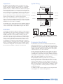
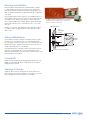
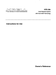
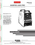
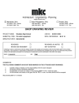
FIRE ALARM SYSTEM CALIFORNIA SQUARE APARTMENTS LOUISVILLE, KENTUCKY SHEETS COVER PAGE C FIRE ALARM SYSTEM F1-F2 FIRE ALARM SYSTEM DETAILS D1 CALIFORNIA SQUARE APARTMENTS LOUISVILLE, KY COVER PAGE JOB NUMBER JLB DS NTS 04-25-2012 REF. N/A SHEET C CALIFORNIA SQUARE APARTMENTS LOUISVILLE, KY 1ST FLOOR F.A. PLAN JOB NUMBER JLB DS 1/8"=1'-0 04-25-2012 REF. E2 SHEET F1 STAIR #1 TO ROOF STAIR #2 TO ROOF F.A. SPEAKER/STROBE LOCATED AT 4TH AND 7TH FLOOR LANDINGS F.A. SPEAKER/STROBE LOCATED AT 4TH AND 7TH FLOOR LANDINGS CALIFORNIA SQUARE APARTMENTS LOUISVILLE, KY 2ND-7TH FLOOR F.A. LAYOUT JOB NUMBER JLB DS 1/8"=1'-0 04-25-2012 REF. E2 SHEET F2 CEILING LINE CALIFORNIA SQUARE APARTMENTS LOUISVILLE, KY FIRE BOTTOM OF DEVICE STROBE/HORN STROBE WIRING DETAILS FACP ANNUNCIATOR 80" MANUAL PULL STATION JOB NUMBER 72" 52" TO 56" JLB 48" DS FLOOR LINE NTS 04-25-2012 REF. N/A SHEET D1 NURSE CALL SYSTEM - extention of the fire alarm system 4850 Crittenden Drive Louisville, KY 40209 p502.363.8633 f502.363.8638 www.alliantintegrators.com California Square Apartments Material Submittal Emergency Call System Professional Sound Systems Educational Systems Healthcare Systems Surveillance & Security Systems Fire Alarm Systems Alliant Integrators, Inc. Submittal Bill-of-Material 4850 Crittenden Dr. Louisville, KY 40209 Project: California Square Apartments Emergency Call System Manufacturer Part No. EST 3-SAC EST KPDISP Cornell EST EST P-512243A SIGA-UIO6R SIGA-MCT2 Cornell E-114-3 Description EST3 Fire Alarm Control Panel (Located In Front Lobby) Security/Access Control Module, Class B Keypad Display (Located In Business Office) Keypad & Liquid Crystal Display st Control Equipment (Located In 1 Floor Mechanical Room UL Listed Power Supply Universal I/O Module Motherboard - 6 Position w/ Riser Selection Dual Input Module – UIO Motherboard Mount Field Devices UL Listed Emergency Station w/ Pull Cord The emergency call system will be an extension of the fire alarm system. We will utilize the existing fire alarm control panel to monitor the emergency stations with pull cords in each tenant’s bedroom and bathroom. In the event of an emergency, the security keypad/fire alarm remote annunciator in the business office will alert staff and the system will also notify authority personnel via the fire alarm system’s dialer and UL listed monitoring agency (Emergency 24). This notification method is consistent with the system that is currently in use at the facility. Professional Sound Systems Educational Systems Healthcare Systems Surveillance & Security Systems Fire Alarm Systems www.alliantintegrators.com This page intentionally blank EST Catalog u EST3 Synergy Hinged Bracket Filler plate (ordered separately) Module Security/Access Control Module Model: 3-SAC Overview The 3-SAC Security/Access Control Module is a key component in the true integration of security and access control functions into the EST3 multiplexed life safety system. The 3-SAC is the demarcation point between fire and security/access functions. For jurisdictions requiring independent wiring of fire and security devices, the 3-SAC offers two independent circuits. Where fire and security devices are permitted to be connected to the same circuit, both circuits can support both fire and security functions. All security devices that connect to a 3-SAC are designed and tested to strict fire alarm standards. For example, to enhance reliability, the 3-SAC can be wired in a Class A (Style 6) configuration, thus delivering an additional level of system survivability over traditional systems employing Class B wiring. The 3-SAC can be used in combination with the Modcom Modem Communicator. The Modcom’s dialer (DACT) function is used to transmit alarms to one or more central monitoring stations and/or paging terminals. Additionally, information received by the Modcom can be downloaded through the 3-SAC to individual security/ access devices. Please refer to the Modcom catalog sheet for additional details Standard Features • Listed for fire, security, and access control • Two supervised RS-485 device circuits • Class A configuration supports 30 Card reader controllers and/or keypad/displays • Class B configuration supports 62 card reader controllers and/or keypad-displays • 4,000 ft (1,220 m) max circuit length • EST3 local rail module • Supports control/display modules • Supervised by the network controller • 100% digital communication • Removable field wiring terminal block Total integration of the EST3 system assures that processing of fire alarm signals always receives the highest priority over routine signal processing. Power for the 3-SAC comes from the same highly reliable power supply/battery combination used to power the fire alarm components. Any Control Display module will mount in front of the 3‑SAC, allowing great flexibility of the system user interface layout. Page 1 of 4 85010-0109 D ATA S H E E T Not to be used for installation purposes. Issue 7.1 Application Engineering Specification The 3-SAC is used to connect the Card Reader Controllers and Keypad Displays to the EST3 network. This permits the network to perform functions network-wide in response to fire and/or security events. A common example is the network’s ability to unlock specified doors in the event of a fire emergency, without the need for hardwired interconnections between fire and access control components. The security and access control module shall be capable of supporting 62 devices on two class B circuits or where added reliability is required, 30 devices on a single Class A circuit. It must be possible to wire Class A in Style 6 configuration. The module shall be capable of supporting both fire and security devices on the same circuit. The module shall permit total integration of the fire, security and access control functions by the system. The module shall be <UL> <ULC> listed for both fire and security applications. The 3-SAC and a simple program rule are all that is required to Class the A wiring unlock doors. Want to disarm security partitions automatically when an authorized 3-SAC Module cardholder enters the building, the 3-SAC and TB2 A B another system rule provide a simple solution. SAC bus SAC bus + + 4 Class A wiring 1 1 3 Typical Wiring 2 3-SAC Module TB2 LCD Keypad CRC CRC A B SAC bus SAC bus + + 4 Class A wiring Class A wiring 1 1 3 3-SAC Module TB2 A B 3-SAC Module SAC bus SAC bus TB2 A + B+ 2 LCD Keypad CRC Class B wiring + + CRC SAC bus SAC bus 4 1 3-SAC Module 4 1 TB2 A B 3 SAC bus SAC bus + + 3 4 1 3 1 LCD LCD Keypad Keypad CRC CRC Class B wiring 3-SAC Module TB2 A B 3-SAC Module SAC bus SAC bus TB2 A + B+ SAC bus SAC bus + 1 TB2 2 CRC Class B wiring Class B wiring + 2 2 3-SAC Module 3 4 4 1 1 CRC CRC + LCD Keypad CRC 120 terminating Resistor 4 CRC 120 terminating Resistor + 1 3 2 CRC A B SAC bus SAC bus LCD Keypad 3 1 2 LCD Keypad CRC 1 1 CRC 120 terminating Resistor 1 2 3 Notes: 1 device 2 installation sheets for proper wiring connections. 3 1 Refer to LCD 120 terminating 1 2 CRC CRC 2 Maximum of 30 devices per loop) (Class B). Keypad Resistor LCD (Class A), 62 devices 120(31 terminating CRC CRC LCD Bus 120 terminating Resistor 3 Security AccessKeypad Control CRC CRC Keypad 4. Up to 4,000 ft. (1,220 m). All wiring is powerResistor limited and supervised. Notes: 2 24Vdc or local transformer for operational power. 5. CRCs 1require 1 Refer to device installation sheets for proper wiring connections. 1 requires 2 KPDISP 24Vdc for power. LCD 120 terminating 2 Maximum of 30 devices (Class A), 62 devices (31 per loop) (Class B). CRC CRC 6 Continuity of theKeypad minus power supply must be LCD from the control panel's 120 terminating Resistor CRC withKeypad CRC maintained all devices communicating with the panel's 3-SAC. 3 Security Access Control Bus Resistor 4. Up to 4,000 ft. (1,220 m). All wiring is power limited and supervised. Notes: 5. CRCs require 24Vdc or local transformer for operational power. Notes: 1 Refer to device installation sheets for proper wiring connections. KPDISP requires 24Vdc for power. 3 3 1 2 Refer to device sheets connections. Maximum of 30 installation devices (Class A), for 62 proper deviceswiring (31 per loop) (Class B).6 2 of 30 devices Class B wiring showing power cabling 3 Maximum Security Access Control (Class Bus A), 62 devices (31 per loop) (Class B). 3 4. 4. 5. 3-SAC Module A B 5. SAC bus SAC bus Control Panel Power supply 24 Vdc + - + + 6 6 Continuity of the minus from the control panel's power supply must be maintained with all devices communicating with the panel's 3-SAC. Security Access Control Up to 4,000 ft. (1,220 m).Bus All wiring is power limited and supervised. Up to 4,000 ft. 24Vdc (1,220 or m).local All wiring is power and supervised. CRCs require transformer for limited operational power. CRCs require 24Vdc or local transformer for operational power. KPDISP requires 24Vdc for power. Additional CRCXF Power Supply KPDISP requires 24Vdcfrom for power. Transformer Continuity of the minus the control panel's power supply must be 24wiring Vdc 16 Vac Class B showing power cabling Continuity the all minus fromcommunicating the control panel's power supply maintainedofwith devices with the panel's + 3-SAC. - must be maintained1with2 all devices communicating with the panel's 3-SAC. Control Panel KPDISP 24 Vdc + - 3 CRC 24 Vdc + - CRC 24 Vdc + - 6 Class B wiring showing power cabling Class B wiring showing power cabling 3-SAC Module Power supply 24 Vdc + - A B SAC bus SAC bus + A B 3-SAC SAC bus Module SAC bus A+ B+ SAC bus SAC bus + 3 3 6 6 Page 2 of 4 Additional Power Additional 6 Supply 24 Vdc Power Supply + Vdc 24 + - CRCXF Transformer CRCXF 16 Vac Transformer + 1 2 1 2 KPDISP 24 Vdc KPDISP +24 Vdc+ - 16 Vac CRC 24 Vdc CRC +24 Vdc+ - CRC 24 Vdc CRC +24 Vdc+ - 6 6 2 KPDISP 24 Vdc + - 3 Additional Power Supply 24 Vdc + - CRCXF Transformer 16 Vac 1 Control Panel Control Panel 3-SAC Module Power supply Power 24 Vdc supply + Vdc 24 + - + 6 CRC 24 Vdc + - CRC 24 Vdc + - CRC 24 Vdc + - CRC 24 Vdc + - 6 CRC 24 Vdc CRC +24 Vdc+ - 85010-0109 D ATA S H E E T Not to be used for installation purposes. Issue 7.1 Specifications Agency Listings Circuit Configuration Circuit Capacity Input Current Wire Size Wire Type Maximum Line Resistance Maximum Capacitance Operating Environment Mounting Ordering Information UL, ULC. See Note 1. Class A or Class B 30 devices on one Class A circuit, 62 devices on two circuits wired Class B 40 mA under all conditions 22 AWG to 14 AWG (0.25mm² to 1.5mm²) Unshielded, twisted pair, > 6 twists per foot 52 Ohms 0.1 µF 0°C to 49° Complete (32°F to 120°F) @ 85%RH, Non-condensing One Local Rail Space Catalog Number 3-SAC 3-FP Description Security/Access Control Module Filler Plate, order separately when no LED or LED/Switch module installed. Shipping Wt. lb (kg) 0.5 (.23) 0.1 (0.05) Note 1: The EST3 is modularly listed under the following standards: UL 864 categories: UOJZ, UOXX, UUKL and SYZV, UL 294 category ALVY, UL 609 category AOTX, UL 636 category ANET, UL 1076 category APOU, UL 365 category APAW, UL 1610 category AMCX, UL 1635 category AMCX ULC-S527, ULC-S301, ULC-S302, ULC-S303, ULC-S306, ULC/ORD-C1076 and ULC/ ORD-C693. Please refer to EST3 Installation and Service Manual for complete system requirements. Page 3 of 4 85010-0109 D ATA S H E E T Not to be used for installation purposes. Issue 7.1 Detection & alarm since 1872 U.S. T 888-378-2329 F 866-503-3996 Canada Chubb-Edwards T 519 376 2430 F 519 376 7258 Southeast Asia T : +65 6391 9300 F : +65 6391 9306 India T : +91 80 4344 2000 F : +91 80 4344 2050 Australia T +61 3 9239 1200 F +61 3 9239 1299 Europe T +32 2 725 11 20 F +32 2 721 86 13 Latin America T 305 593 4301 F 305 593 4300 utcfireandsecurity.com © 2010 UTC Fire & Security. All rights reserved. 85010-0109 D ATA S H E E T Not to be used for installation purposes. Issue 7.1 06-21-10 Page 4 of 4 EST Catalog u EST3 Synergy Keypad/Display KPDISP The keypad lies discreetly hidden behind the cover, while the message remains front and center at all times. Overview Standard Features The KPDISP is a combination keypad and dot-matrix display designed for use with the EST3 integrated system. The unit features a large LCD display and telephone-style keypad housed in an attractive Cycoloy® case. A removable cover is provided to prevent accidental keypad activation and protect against dirt. • Listed for fire and security The KPDISP transmits and receives information from/to the 3-SAC Security Access Control module installed in the EST3 system. Communications between the KPDISP and the 3-SAC are supervised, providing the ultimate in reliability. Credential holder information is encrypted to provide an additional level of security. KPDISP data is stored in non-volatile memory. Power to the KPDISP is provided by the EST3, ensuring a reliable, supervised and backedup power source. • Removable protective cover The KPDISP supports bilingual operation, and can be programmed to automatically display the language of the user. • 128 x 64 backlit dot matrix LCD display • Telephone style keypad with tactile & audible feedback • Aesthetically pleasing design • 200 users and 9999 pin codes • Supports bilingual operation • Integral help function • Menu driven • Non-volatile memory • Electronic addressing The display is backlit, and lights whenever a key is pushed. An automatic timer extinguishes the light after a brief delay. The keypad features tactile and audible feedback and is backlit at all times. To aid in locating the keypad in the dark, the back lighting is visible even with the cover closed. Page 1 of 4 85006-0046 D ATA S H E E T Not to be used for installation purposes. Issue 5 Application All operations are menu driven. The most common use of the KPDISP is arming and disarming security partitions. The KPDISP may be optionally configured to display on its LCD the primary partition’s status, i.e.: whether it is armed or disarmed. This option provides an added measure of security in situations that warrant it. The display also permits a user to identify off-normal points and take corrective action. If the problems can’t be corrected, the user can have the option to bypass a point before arming the system. When used with EST3 and the 3-MODCOM, openings and closing may be sent automatically to a central monitoring station. Each of up to 200 authorized users is assigned a pass code consisting of a unique three-digit number and a four-digit PIN number. Duplicate PINs are permitted by the KPDISP, so a user can pick a number that is easy for them to remember. Typical Wiring POWER – + – – + + 24 Vdc supply 24 Vdc supply From last device To next device – – + + RS-485 line – RS-485 line + DATA The KPDISP can also annunciate fire functions and be programmed to act as a full function fire annunciator. In the event of a problem, context-sensitive help is readily available using the HELP button. Installation The KPDISP is designed to facilitate installation in a wide variety of indoor applications. The unit can be mounted directly on a wall or using a 4” or 100mm square or 2-gang electrical box. To ensure reliability, terminal blocks are provided for all wiring. One pair carries data in and out of the unit, while the second pair provides power. These specially-designed terminal blocks provide unique features aimed at maintaining system operation during commissioning or servicing. Should a KPDISP be removed from its rear mounting plate, the terminals automatically provide continuity to downstream devices. This helps ensure continued communication with the control panel, despite the removal of a KPDISP from the communication wiring path. The unit features electronic addressing so there are no jumpers or switches to set in the unit. Control Panel Additional Power Supply 24 Vdc + - Power supply 24 Vdc + - CRC 24 Vdc + - KPDISP 24 Vdc + - 1 1 KPDISP 24 Vdc + - 1 Minus common from control panel must be maintained. Engineering Specification The Security/Access Control user interface shall provide both display and keypad functions to indicate system status and arming/disarming the system. The unit shall support additional display functions such as fire/security annunciation. The display shall be capable of bi-lingual operation under the direction of the system controller and/or access control credential. The unit shall feature a backlit 128 x 64 dot matrix LCD readout. The keypad shall provide both tactile and audible user feedback to facilitate entry of information. User entries shall be menu driven, and capable of executing system commands. A context sensitive help system shall be available to the user at any time. All keypad/display addressing shall be electronic, jumpers or DIP switches shall not be considered as equivalent to electronic addressing. All data within the unit shall be stored in non-volatile memory to prevent data loss. The unit shall be constructed of a thermoplastic housing with integral (removable) cover, and be suitable for mounting directly on a finished wall or standard 4” square or 2-gang electrical boxes. All wiring terminations shall be to an integral terminal strip. <It shall be possible to transmit openings and closing performed at the keypad to the central monitoring station>. Page 2 of 4 85006-0046 D ATA S H E E T Not to be used for installation purposes. Issue 5 Specifications Agency Listings Circuit Configuration Power Requirements Wire Size Dimensions (HWD) Finish Communications Supported Languages Operating Environment Mounting Users Partitions Supported UL, ULC. See Note 1. Class A or Class B 24 Vdc @ 38 mA 14 AWG (1.5mm²) - 22 AWG (0.25mm²) 4 ¾” x 7 ¼” x 1 ¼” (12.7cm x 18.4cm x 3.2cm) - open height 8.72” (22.15cm) White high-impact Cycoloy® RS-485 English, Spanish, French, Hebrew, Italian, Dutch, Polish, Russian, Turkish, Portuguese, Slovak 0°C to 49°C Complete (32°F to 120°F) @ 0 to 93%RH, Non-condensing 4” or 100mm square or 2-gang electrical boxes 200 max. per KPDISP 255 max. per KPDISP Note 1: The EST3 is modularly listed under the following standards: UL 864 categories: UOJZ, UOXX, UUKL and SYZV, UL 294 category ALVY, UL 609 category AOTX, UL 636 category ANET, UL 1076 category APOU, UL 365 category APAW, UL 1610 category AMCX, UL 1635 category AMCX ULC-S527, ULC-S301, ULC-S302, ULC-S303, ULC-S306, ULC/ ORD-C1076, ULC/ORD-C693. Please refer to EST3 Installation and Service Manual for complete system requirements. Ordering Information Catalog Number KPDISP KPDISP-CF Page 3 of 4 Description Keypad Display Configuration Software CD ROM Shipping Wt., lb (kg) 1 (0.45) 85006-0046 D ATA S H E E T Not to be used for installation purposes. Issue 5 Detection & alarm since 1872 U.S. T 888-378-2329 F 866-503-3996 Canada Chubb-Edwards T 519 376 2430 F 519 376 7258 Southeast Asia T : +65 6391 9300 F : +65 6391 9306 India T : +91 80 4344 2000 F : +91 80 4344 2050 Australia T +61 3 9239 1200 F +61 3 9239 1299 Europe T +32 2 725 11 20 F +32 2 721 86 13 Latin America T 305 593 4301 F 305 593 4300 utcfireandsecurity.com © 2010 UTC Fire & Security. All rights reserved. 85006-0046 D ATA S H E E T Not to be used for installation purposes. Issue 5 06-21-10 Page 4 of 4 P-512243A - 12 or 24 Volt, Power Supply P-512243A RN CO EL L The Cornell P-512243A is UL listed for fire alarm, burglar alarm, access control applications and hospital signaling - nurse call equipment. Termination: Screw terminals. Exterior: Grey, baked enamel finish. Dimensions: 13.5” H x 12.75” W x 3.25” D Rated Output: 4 amps continuous supply current at 12 VDC and 3 amps continuous supply current at 24 VDC. Power: 115VAC/60Hz, 1.45 amp. 4 amps continuous supply current at 12VDC(switch closed), 3 amps continuous supply current at 24 VDC (switch open). Circuit Protection: Short circuit and thermal overload protection. Indicator LED Diagnostics: Red-DC Green-AC Status On On Normal Operating condition On Off Loss of AC Off On No DC output Off Off Loss of AC Discharged. No DC output Mounting: Slotted keyholes make it suitable for vertical wall or rack mounting. ENGINEERING SPECIFICATIONS The contractor shall furnish and install a CORNELL P-512243A Power Supply for use with the CORNELL Series. The power supply shall operate at 115 volts AC 60Hz. Enclosures provided with cam lock and field wiring on the units shall utilize screw terminals. 1-800-558-8957 This page intentionally blank EST Catalog u Intelligent Input-Output Universal Input/ Output Module Motherboards SIGA-UIO6R SIGA-UIO2R, SIGA-UIO6R, SIGA-UIO2R Overview Standard Features Signature Series Universal Input-Output Module Motherboards provide mounting and wiring terminations for up to six Signature Series plug-in UIO (SIGA-“M” series) modules. UIO motherboards slide into a rigid extruded track (included) with mounting pads for convenient mounting into a variety of equipment enclosures. UIO modules plug into the board and are held securely in place with captive machine screws. All field wiring connects to terminal blocks on the motherboard, which permits rapid removal and replacement of modules for troubleshooting. • Modular flexibility Wide assortment of multi-function plug-in modules provides total flexibility. The SIGA-UIO2R provides mounting and wiring terminations for up to two UIO modules, and the SIGA-UIO6R provides mounting and wiring terminations for up to six UIO modules. Both motherboards feature a riser #1 input and a riser #2 input bus. Jumpers on riser #1 input, between modules, facilitate sharing a single riser among more than one module. This significantly reduces wiring requirements. Removing the jumpers provide separate riser inputs to each adjacent module. Riser #2 input is fixed to each module position and cannot be split. The SIGA-UIO6 provides mounting and wiring terminations for up to six UIO modules. This motherboard provides two riser inputs that are common to all modules. • Minimum wiring requirements Integral jumpers between modules allow sharing of risers to reduce installation wiring. • Easy installation #12 AWG (2.5 mm2) terminal blocks and sturdy mounting pads ensure quick installation into Edwards enclosures. • Supports automatic device mapping All compatible UIO modules transmit information to the loop controller regarding their circuit locations with respect to other Signature devices on the wire loop. • Supports intelligent devices On-board modules make decisions and input an alarm from initiating devices connected to them even if the loop controller’s polling interrogation stops. • Twisted or shielded wire not required Because all decisions are made at the on-board modules, lower communication speeds are possible. This results in substantially improved control panel response time and less sensitivity to line noise and loop wiring properties. • Supports electronic addressing Programmable addresses are downloaded to compatible UIO modules from the loop controller, a PC, or the SIGA-PRO Signature Program/Service Tool. There are no switches or dials to set. Page 1 of 4 85001-0365 D ATA S H E E T Not to be used for installation purposes. Issue 3.1 Mounting and Installation Mount the UIO motherboard inside a Edwards MFC-A cabinet or other suitable electrical enclosure with screws and washers provided. Each MFC-A will hold one UIO2R motherboard or one UIO6 or UIO6R motherboard complete with their full complement of modules. Plug a Signature Series UIO module into any available position on the motherboard and secure the module to the motherboard with the captive screws. Wiring connections are made to the terminals on the motherboard (see wiring diagram). UIO motherboard terminals are suited for #12 to #18 AWG (2.5 mm2 to 0.75 mm2) wire size. Edwards recommends that all boards and modules be installed according to latest recognized edition of national and local fire alarm codes. Testing & Maintenance The module’s automatic self-diagnosis identifies when it is defective and causes a trouble message. The user-friendly maintenance program shows the current state of each module and other pertinent messages. Single modules may be turned off (de-activated) temporarily, from the control panel. Scheduled maintenance (Regular or Selected) for proper system operation should be planned to meet the requirements of the Authority Having Jurisdiction (AHJ). Refer to current NFPA 72 and ULC CAN/ULC 536 standards. The MFC-A cabinet is UL listed for use with UIO motherboards and meets requirements for spacing and clearance around the components. UIO Motherboard 6-32 Self-tapping screws Plug-in (UIO) Module Captive screws #6 Flat washers Cabinet or electrical enclosure Compatibility Signature Series Universal Input/Output Module Boards are compatible only with SIGA-“M” Series I/O Modules, which require a Signature Data Controller. Warnings & Cautions Signature devices will not operate without electrical power. As fires frequently cause power interruption, we suggest you discuss further safeguards with your fire protection specialist. Page 2 of 4 85001-0365 D ATA S H E E T Not to be used for installation purposes. Issue 3.1 Typical Wiring Signature Series Universal Input/Output Motherboards have terminal blocks to accept #18 AWG (0.75mm2 ), #16 AWG (1.0mm2), #14 AWG (1.5mm2 ), and #12 AWG (2.5mm2) wire sizes. See Signature Data Controller catalog sheets for detailed wiring requirements and specifications. SIGA-UIO2R SIGA-UIO6R Module Input/Output Wiring Refer to individual module installation sheet for wiring details. 3 Module Input/Output Wiring UIO2R Data In 1 2 3 4 1 2 3 4 1 2 3 4 UIO6R TB5 TB6 1 2 3 4 Data In TB7 TB15 4 3 2 1 4 3 2 1 Data Out Signature Data Circuit Common input/output bus for M series modules 4 3 2 1 TB7 TB15 1 Jumpers may be used to make the inputs/outputs between modules common. 2) Not all modules use the SIGA-UIO2R terminals for the same functions. 3 Refer to individual SIGA-M series installation sheets for jumper settings and wiring information. Installations with multiple SIGA-UIO motherboards or enclosures (which include other wiring) require FPL, FPLR, FPLP, or equivalent NEC-approved wire for all power limited wiring. Observe the details of supervision and power limited versus non-power limited circuits. Refer to the SIGA-M series installation sheets. Signature Data Circuit 4) Do not mix incompatible signals. Data Out 5 Maximum current is 8 Amps. 7) Refer to Signature Data Controller Installation Sheets for wiring 1 2 3 4 1 2 3 4 TB13 1 2 3 4 TB12 1 2 3 4 TB11 1 2 3 4 1 2 3 4 Module Input/Output Wiring (maximum current is 8 Amps) Refer to individual module installation sheet for wiring details. SIGA-UIO6 TB1 Module Input/Output Wiring Refer to individual module installation sheet for wiring details. Data In 4 3 2 1 1 2 3 4 1 2 3 4 1 2 3 4 1 2 3 4 1 2 3 4 TB6 Notes Jumpers connect common inputs outputs between modules. TB5 5 TB4 3 1 TB3 Module Input/Output Wiring Jumpers connect common inputs/outputs between modules TB9 1 2 3 4 TB10 Data Out TB9 1 2 3 4 TB2 TB8 Input/Output Bus 2 Common to all M series modules (maximum current is 8 Amps) 4 3 2 1 5 TB8 Signature Data Circuit 1 2 3 4 TB4 1 2 3 4 TB2 TB1 TB1 TB3 1 2 3 4 TB2 1 2 3 4 1 2 3 4 UIO6 TB14 4 3 2 1 TB15 TB7 4 3 2 1 Input/Output Bus 1 Common to all M series modules (maximum current is 8 Amps) Input/Output Bus 2 Common to all M series modules (maximum current is 8 Amps) specifications. Page 3 of 4 85001-0365 D ATA S H E E T Not to be used for installation purposes. Issue 3.1 Specifications Catalog Number Module Capacity Detection & alarm since 1872 U.S. T 888-378-2329 F 866-503-3996 Canada Chubb-Edwards T 519 376 2430 F 519 376 7258 Southeast Asia T : +65 6391 9300 F : +65 6391 9306 India T : +91 80 4344 2000 F : +91 80 4344 2050 Australia T +61 3 9239 1200 F +61 3 9239 1299 Europe T +32 2 725 11 20 F +32 2 721 86 13 Latin America T 305 593 4301 F 305 593 4300 Dimensions (with module installed) Address Requirements Type Code Compatible Modules Operating Voltage Mounting (cabinets) Wiring Terminals Storage and Operating Environment Agency Listing SIGA-UIO6R Six SIGA-UIO6 Six 9.56 inch L (across mounting feet) x 4.3 inch W x 3.2 inch H no address required none All SIGA-Mxxx Signature Series 15.2 to 19.95 Vdc (19 Vdc nominal) Directly into suitable enclosures (e.g.: MFC-A) - Notes 1, 2, 3. #12 AWG (2.5mm²) to #18 AWG (0.75mm²) Operating Temperature: 32°F to 120°F (0°C to 49°C) Storage Temperature: -4°F to 140°F (-20°C to 60°C) Operating and Storage Humidity: 0 to 93% RH UL, ULC, MEA, CSFM Notes: 1. Allow a minimum clearance of one inch around all sides of the UIO motherboard. 2. On-site drilling of mounting holes may be required. Self-tapping mounting screws are provided. 3. Suitable cabinets: MFC-A, 2-WB, 2-WB3, 2-WB7, CAB2, 3-CAB5, 3-CAB7, 3-CAB14, 3-CAB21, 3-RCC series, RACC series. Ordering Information Catalog Number SIGA-UIO2R utcfireandsecurity.com SIGA-UIO6R © 2010 UTC Fire & Security. All rights reserved. SIGA-UIO6 MFC-A Ship Wt. - lb (kg) Description Universal Input-Output Module Board w/Riser Inputs - Two Module Positions Universal Input-Output Module Board w/Riser Inputs - Six Module Positions Universal Input-Output Module Board - Six Module Positions UL listed cabinet for mounting UIO motherboards, red with white “FIRE” 8 inch H X 14 inch W X 3.5 inch D (203 mmH X 356 mm W X 89 mm D) 0.32 (0.15) 0.62 (0.28) 0.56 (0.25) 7.0 (3.1) 85001-0365 D ATA S H E E T Not to be used for installation purposes. Issue 3.1 06-21-10 Page 4 of 4 SIGA-UIO2R Two 5.4 inch L (across mounting feet) x 4.3 inch W x 3.2 inch H EST Catalog u Intelligent Input-Output Input Modules SIGA-CT1, SIGA-CT2 & SIGAMCT2 SIGA-CT1/2 SIGA-MCT2 MEA S CHINA Application Notes Available Overview Standard Features The SIGA-CT1 Single Input Module and SIGA-CT2/SIGA-MCT2 Dual Input Modules are intelligent analog addressable devices used to connect one or two Class B normally-open Alarm, Supervisory, or Monitor type dry contact Initiating Device Circuits (IDC). • Multiple applications Including Alarm, Alarm with delayed latching (retard) for waterflow applications, Supervisory, and Monitor. The installer selects one of four “personality codes” to be downloaded to the module through the loop controller. The actual function of these modules is determined by the “personality code” selected by the installer. This code is downloaded to the module from the Signature loop controller during system configuration. The input modules gather analog information from the initiating devices connected to them and convert it into digital signals. The module’s on-board microprocessor analyzes the signal and decides whether or not to input an alarm. The SIGA-CT1 and SIGA-CT2 mount to standard North American 1-gang electrical boxes, making them ideal for locations where only one module is required. Separate I/O and data loop connections are made to each module. The SIGA-MCT2 is part of the UIO family of plug-in Signature Series modules. It functions identically to the SIGA-CT2, but takes advantage of the modular flexibility and easy installation that characterizes all UIO modules. Two- and six-module UIO motherboards are available. All wiring connections are made to terminal blocks on the motherboard. UIO assemblies may be mounted in Edwards enclosures. • SIGA-CT1 rated for high temperature environments Suitable for attic installation and monitoring high temperature heat detectors. • Plug-in (UIO) or standard 1-gang mount UIO versions allow quick installation where multiple modules are required. The 1-gang mount version is ideal for remote locations that require a single module. • Automatic device mapping Signature modules transmit information to the loop controller regarding their circuit locations with respect to other Signature devices on the wire loop. • Electronic addressing Programmable addresses are downloaded from the loop controller, a PC, or the SIGA-PRO Signature Program/Service Tool. There are no switches or dials to set. • Stand-alone operation The module makes decisions and inputs an alarm from initiating devices connected to it even if the loop controller’s polling interrogation stops. (Function availability dependent upon control panel.) • Ground fault detection by address Detects ground faults right down to the device level. Page 1 of 4 85001-0241 D ATA S H E E T Not to be used for installation purposes. Issue 7.1 Signature Series Overview UIO Motherboard The Signature Series intelligent analog-addressable system from Edwards Security is an entire family of multi-sensor detectors and mounting bases, multiple-function input and output modules, network and non-network control panels, and user-friendly maintenance and service tools. Analog information from equipment connected to Signature devices is gathered and converted into digital signals. An onboard microprocessor in each Signature device measures and analyzes the signal and decides whether or not to input an alarm. The microprocessor in each Signature device provides four additional benefits – Self-diagnostics and History Log, Automatic Device Mapping, Stand-alone Operation and Fast, Stable Communication. Self-diagnostics and History Log – Each Signature Series device constantly runs self-checks to provide important maintenance information. The results of the self-check are automatically updated and permanently stored in its non-volatile memory. This information is accessible for review any time at the control panel, PC, or using the SIGA-PRO Signature Program/Service Tool. Automatic Device Mapping –The Signature Data Controller (SDC) learns where each device’s serial number address is installed relative to other devices on the circuit. The SDC keeps a map of all Signature Series devices connected to it. The Signature Series Data Entry Program also uses the mapping feature. With interactive menus and graphic support, the wired circuits between each device can be examined. Layout or “as-built” drawing information showing branch wiring (T-taps), device types and their address are stored on disk for printing hard copy. Installation SIGA-CT1 and SIGA-CT2: modules mount to North American 2½ inch(64 mm) deep 1-gang boxes and 1½ inch (38 mm) deep 4 inch square boxes with 1-gang covers and SIGA-MP mounting plates. The terminals are suited for #12 to #18 AWG (2.5 mm2 to 0.75 mm2) wire size. Compatible electrical box Wall plate, white (1-gang) M ALAR FIRE DULE MO Status LEDs LED viewing ports SIGA-MCT2: mount the UIO motherboard inside a suitable Edwards enclosure with screws and washers provided. Plug the SIGA-MCT2 into any available position on the motherboard and secure the module to the motherboard with the captive screws. Wiring connections are made to the terminals on the motherboard (see wiring diagram). UIO motherboard terminals are suited for #12 to #18 AWG (2.5 mm2 to 0.75 mm2) wire size. Page 2 of 4 6-32 Self-tapping screws Plug-in (UIO) Module Captive screws #6 Flat washers Cabinet or electrical enclosure Electronic Addressing - The loop controller electronically addresses each module, saving valuable time during system commissioning. Setting complicated switches or dials is not required. Each module has its own unique serial number stored in its on-board memory. The loop controller identifies each device on the loop and assigns a “soft” address to each serial number. If desired, the modules can be addressed using the SIGA-PRO Signature Program/Service Tool. Edwards recommends that this module be installed according to latest recognized edition of national and local fire alarm codes. Application The duty performed by the SIGA-CT1 and SIGA-CT2/MCT2 is determined by their sub-type code or “Personality Code”. The code is selected by the installer depending upon the desired application and is downloaded from the loop controller. One personality code can be assigned to the SIGA-CT1. Two personality codes can be assigned to the SIGA-CT2/MCT2. Codes 1, 2, 3 and 4 can be mixed on SIGA-CT2/MCT2 modules only. For example, personality code 1 can be assigned to the first address (circuit A) and code 4 can be assigned to the second address (circuit B). NORMALLY-OPEN ALARM - LATCHING (Personality Code 1) - Assign to one or both circuits. Configures either circuit A or B or both for Class B normally open dry contact initiating devices such as Pull Stations, Heat Detectors, etc. An ALARM signal is sent to the loop controller when the input contact is closed. The alarm condition is latched at the module. NORMALLY-OPEN ALARM - DELAYED LATCHING (Personality Code 2) - Assign to one or both circuits. Configures either circuit A or B or both for Class B normally-open dry contact initiating devices such as Waterflow Alarm Switches. An ALARM signal is sent to the loop controller when the input contact is closed for approximately 16 seconds. The alarm condition is latched at the module. NORMALLY-OPEN ACTIVE - NON-LATCHING (Personality Code 3) - Assign to one or both circuits. Configures either circuit A or B or both for Class B normally-open dry contact monitoring input such as from Fans, Dampers, Doors, etc. An ACTIVE signal is sent to the loop controller when the input contact is closed. The active condition is not latched at the module. NORMALLY-OPEN ACTIVE - LATCHING (Personality Code 4) - Assign to one or both circuits. Configures either circuit A or B or both for Class B normally open dry contact monitoring input such as from Supervisory and Tamper Switches. An ACTIVE signal is sent to the loop controller when the input contact is closed. The active condition is latched at the module. 85001-0241 D ATA S H E E T Not to be used for installation purposes. Issue 7.1 Typical Wiring Modules will accept #18 AWG (0.75mm2), #16 (1.0mm2), and #14AWG (1.50mm2), and #12 AWG (2.50mm2) wire sizes. Note: Sizes #16 AWG (1.0mm2) and #18 AWG (0.75mm2) are preferred for ease of installation. See Signature Loop Controller catalog sheet for detailed wiring requirement specifications. Initiating (Slave) Device Circuit Wire Specifications Maximum Allowable Wire Resistance Maximum Allowable Wire Capacitance For Design Reference: 50 ohms (25 ohms per wire) per Circuit 0.1µF per Circuit Maximum Distance to EOLR Wire Size #18 AWG (0.75 mm²) #16 AWG (1.00 mm²) 4,000 ft (1,219 m) #14 AWG (1.50 mm²) #12 AWG (1.50 mm²) SIGA-CT2 SIGA-CT1 Typical NO Initiating Device NOTES 1 Maximum 25 Ohm resistance per wire. UL/ULC Listed 47KW EOL Input 2 UL/ULC Listed 47KW EOL Input 1 2 Maximum #12 AWG (2.5 mm² ) wire; Minimum #18 AWG (0.75 mm2). 1 2 4 3 Refer to Signature controller installation sheet for wiring specifications. 4 Maximum 10 Vdc @ 350 µA MCT2 1 23 4 5 The SIGA-UIO6R and the SIGA-UIO2R do not come with TB14. This module will not operate without electrical power. As fires frequently cause power interruption, we suggest you discuss further safeguards with your local fire protection specialist. Compatibility TB14 TB7 473387351 Data Out 4 3 2 1 CAT NO. Signature Data Circuit Warnings & Cautions 4 3 2 1 Data In 7 These modules will not support 2-wire smoke detectors. MCT2 6 All wiring is supervised and power-limited. UIO(R) series motherboard 3 Green LED (Normal) Red LED (Active) 5 No connections required for MCT2 Other modules may require connections. 4 3 2 1 TB15 1 2 3 4 No connections or jumper settings required for MCT2. SIGA-MCT2 The Signature Series modules are compatible only with EST’s Signature Loop Controller. Page 3 of 4 85001-0241 D ATA S H E E T Not to be used for installation purposes. Issue 7.1 Specifications Detection & alarm since 1872 U.S. T 888-378-2329 F 866-503-3996 Canada Chubb-Edwards T 519 376 2430 F 519 376 7258 Southeast Asia T : +65 6391 9300 F : +65 6391 9306 India T : +91 80 4344 2000 F : +91 80 4344 2050 Australia T +61 3 9239 1200 F +61 3 9239 1299 Europe T +32 2 725 11 20 F +32 2 721 86 13 Latin America T 305 593 4301 F 305 593 4300 utcfireandsecurity.com © 2010 UTC Fire & Security. All rights reserved. Catalog Number Description Type Code Address Requirements Operating Current Operating Voltage Construction Mounting Storage and Operating Environment LED Operation Compatibility Agency Listings SIGA-CT1 SIGA-CT2 SIGA-MCT2 Dual Input Module Single Input Module 49 (factory set) Four sub-types (personality 48 (factory set) Four codes) are available sub-types (personality codes) are available Uses Two Module Addresses Uses One Module Address Standby = 396µA; Activated = 680µA Standby = 250µA; Activated = 400µA 15.2 to 19.95 Vdc (19 Vdc nominal) High Impact Engineering Polymer UIO2R/6R/6 MotherNorth American 2½ inch (64 mm) deep oneboard gang boxes and 1½ inch (38 mm) deep 4 inch square boxes with one-gang covers and SIGAMP mounting plates Operating Temperature: Operating Temperature: 32°F to 120°F 32°F to 158°F (0°C to 49°C) (0°C to 70°C) Storage Temperature: -4°F to 140°F Storage Temperature: (-20°C to 60°C) -4°F to 140°F (-20°C to 60°C); Humidity: 0 to 93% RH Humidity: 0 to 93% RH On-board Green LED - Flashes when polled; On-board Red LED Flashes when in alarm/active Both LEDs - Glow steady when in alarm (stand-alone) Use with Signature Loop Controller UL, ULC, MEA, CSFM Ordering Information Catalog Number SIGA-CT1 SIGA-CT2 SIGA-MCT2 Description Single Input Module — UL/ULC Listed Dual Input Module — UL/ULC Listed Dual Input Plug-in (UIO) Module — UL, ULC Listed Related Equipment 27193-11 Surface Mount Box - Red, 1-gang 27193-16 Surface Mount Box - White, 1-gang SIGA-UIO2R Universal Input-Output Module Board w/Riser Inputs — Two Module Positions SIGA-UIO6R Universal Input-Output Module Board w/Riser Inputs — Six Module Positions SIGA-UIO6 Universal Input-Output Module Board — Six Module Positions MFC-A Multifunction Fire Cabinet — Red, supports Signature Module Mounting Plates SIGA-MB4 Transponder Mounting Bracket (allows for mounting two 1-gang modules in a 2-gang box) Signature Module Mounting Plate, 1 footprint Signature Module Mounting Plate, 1/2 footprint Signature Module Mounting Plate, 1/2 extended footprint SIGA-MP1 SIGA-MP2 SIGA-MP2L 1.0 (0.6) 1.0 (0.6) 0.32 (0.15) 0.62 (0.28) 0.56 (0.25) 7.0 (3.1) 0.4 (0.15) 1.5 (0.70) 0.5 (0.23) 1.02 (0.46) 85001-0241 D ATA S H E E T Not to be used for installation purposes. Issue 7.1 06-21-10 Page 4 of 4 Ship Wt. lbs (kg) 0.4 (0.15) 0.4 (0.15) 0.1 (0.05) Visual Nurse Call 4000 Single Status Emergency Stations – Pull String with auxiliary contact and LED options E-114, E-114-1, and E-114-3 Description: E-114, E-114-1 and E-114-3 Emergency Stations feature satin finished stainless steel faceplates with silk-screened designations. They may be flush mounted on standard outlet boxes with single-gang rings, or surface mounted on Wiremold 5748 or equal with a depth requirement of 1 ¾“. Field wiring terminations are wire leads. E-114/E-114-1 E-114-3 The E-114, E-114-1 and E-114-3 have DPDT contacts and pigtail wires. The E-114 has four; the E-114-1 has seven and the E-114-3 has eight pigtail wires. Operation: Pulling the six-foot nylon cord on CORNELL’s Emergency Station activates a call for help. The E-114-3 also has a LED light to confirm call placement. To cancel the call, slide the switch to the off position. Mounting: The satin finish stainless steel faceplate with silk-screened designations may be flush mounted on a standard outlet box with single-gang plaster ring, or surface mounted on a Wiremold 5748 or equivalent. Engineering Specifications: The contractor shall furnish and install these CORNELL Emergency Stations as indicated on the plans. Faceplates shall be satin-finish stainless steel with silk-screened designations. Calls in progress can be cancelled by moving the switch to off position. (A red LED on the E-114-3 indicates calls in progress). Stations shall be mounted on standard outlet boxes with single-gang rings or Wiremold 5748 or equivalent. Technical Information: Power Requirements: 24VDC Operating Environment: 50-120°F Indoor Non-condensing Physical Faceplate Dimensions: 4 ½ ”H x 2 ¾ ”W (Standard 1 Gang) Mounting: Single-Gang back box with 1¾” minimum depth Wiring: Field wiring terminations are wire leads. DE114CM Available in 1-6 gang sizes: *stations are only UL Listed in the 1 gang size *For correct part number, change first number (1) to gang size needed