1
Checkout and Maintenance
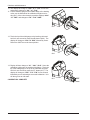
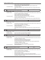
7. Make sure all the SAPE arms are in the home position.
8. Remove the “dummy plug” from the secure disk slot and install the new software. Please NOTE that the
secure disk will only go in one way DO NOT FORCE the media into the opening.
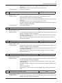
9. Power up the balancer. When the unit begins to continually emit beeps the download process is complete. Turn off the balancer, remove the software and reinstall the “dummy plug” and re-boot.
10. After the re-boot process the balancer will identify itself. Press the <ENTER> button to confirm the model
number. The balancer will reboot. If the balancer is Snapon Low Digital or JBC System II the technician will need to use the <P> or <F> to toggle and select the correct model. If the balancer is a
System III it will be necessary to program either “3-b” basic vibratory or press the “F” to toggle
“3-P” for a power clamp unit. Press the “ENTER” key to confirm the model selected. If the wrong
model is selected the technician will need to perform an F/P 95 to clear the EEprom.
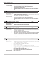
11. It may be necessary to perform an extended F50 (digital balancer). The supply voltage from the old system to the new system has changed from 5.0V to 3.3V therefore it will be necessary to reset the value of
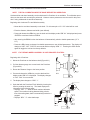
PO 220. Place the distance gauge in the home position and program <F/P 50>. Verify the home position
voltage mentioned in step 12. Press the <F/P> button, the display changes to “1 - 1”, press it again the
display will change to “2 - 2” and then finally 3 after the final press “Set dis 220” will be displayed saving
the home voltage to PO 220”.
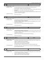
12. Complete all necessary factory calibration procedures, use the service manual for proper procedures.
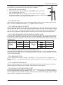
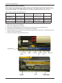
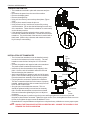
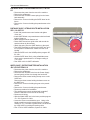
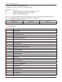
C80 - Distance/ Diameter gauge calibration
B
Distance (F50) 3.08 - 3.12 Small Cabinet
A
3.08 - 3.12 Medium/Large Cabinet
F51
Diameter (F51) 3.05 - 3.15 On the Vibratory Tube (A)
2.80 - 2.90 On Bell Housing (B)
Width (F52) 3.10 - 3.20
C83 - Vibratory calibration
C84 - Empty shaft calibration
C88 - Top Dead Center (TDC) calibration.
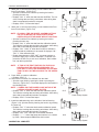
13. Mount a Tire and Wheel assembly. Using the SAPE assembly verify all data taken matches the tire and
wheel being used. Balance the Tire and Wheel assembly to verify operation.
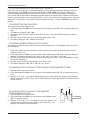
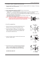
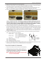
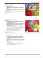
TO ACCESS THE INSIDE OF THE MACHINE
1. Remove the screws from the front and rear of the weight tray.
2. Standing at the front of the machine, rotate the SAPE arm to
it’s full most outward position. Lift and remove the weight tray.
Avoid breaking or damaging wire harnesses. Harnesses may
be held in place with various retainer clips.
NOTE: WHEN INSTALLING THE WEIGHT TRAY, BE CAREFUL NOT TO CRUSH WIRES.
1-17