1
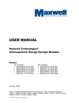
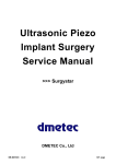
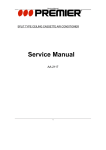
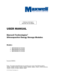
SPLIT TYPE WALL MOUNTED AIR CONDITIONER
Service Manual
AA-2119
Service Manual
CONTENTS
1. Range & Conditions ..................................................................................... 2
1.1 Operating Range .......................................................................................................... 2
1.2 Operating Conditions................................................................................................... 2
2. Specifications ............................................................................................... 3
2.1 Unit Specifications ....................................................................................................... 3
2.2 Specifications of main parts........................................................................................ 4
2.3 Specifications of other parts ....................................................................................... 6
3. Control Specifications ................................................................................. 7
3.1 System source.............................................................................................................. 7
3.2 Control functions ......................................................................................................... 7
3.3 Operating mode............................................................................................................ 8
3.4 Protection function .................................................................................................... 10
3.5 Other functions........................................................................................................... 12
3.6 Parameter table .......................................................................................................... 14
4. Dimensional Data ....................................................................................... 15
5. Performance Charts ................................................................................... 18
6. Refrigerant Flow Diagram.......................................................................... 19
7. Circuit Diagram........................................................................................... 20
7.1 Electrical wiring diagram for outdoor unit ............................................................... 20
7.2 Electrical wiring diagram for indoor unit ................................................................. 20
8. Troubleshooting ......................................................................................... 21
8.1 Check before troubleshooting .................................................................................. 21
8.2 The air conditioner does not work............................................................................ 22
8.3 Some parts of the air conditioner do not work ........................................................ 24
8.4 Air conditioner operates, but abnormalities are observed ..................................... 26
8.5 Sensor is defective (Check reference 3.4.8)............................................................. 27
9. Checking Electrical Components.............................................................. 27
9.1 Measure insulation resistance .................................................................................. 27
9.2 Checking continuity of fuse on PCB Ass'y .............................................................. 28
9.3 Checking motor capacitor ......................................................................................... 28
1
Service Manual
Technical Data
1. Range & Conditions
1.1 Operating Range
Operating Modes
Temperature
Indoor Temperature
Outdoor Temperature
Max.
32℃ DB/23℃ WB
43℃ DB
Min.
21℃ DB/15℃ WB
21℃ DB
Cooling
1.2 Operating Conditions
Rated Operating Conditions
Cooling
Indoor Temperature
Outdoor Temperature
27℃ DB/19℃ WB
35℃ DB/24℃ WB
Tubing Length (m)
4.0
Max. Operating Value
Indoor Temperature
Cooling
Outdoor Temperature
32℃ DB/23℃ WB
Tubing Length (m)
43℃ DB
4.0
DB: Dry-bulb temperature
WB: Wet-bulb temperature
2
Service Manual
2. Specifications
2.1 Unit Specifications
220V/ 60Hz (single phase)
Rated voltage & Power
Performance
Cooling
Rated capacity
Air circulation (High)
Moisture removal (High)
Btu/h
m3/h
L/h
9000
420
1.1
Cooling
Electrical rating
Voltage range
Operating current
Power input
E.E.R
V
A
W
W/W
198~242
4.80
1000
2.64
Features
Controls / Temperature control
Control unit
Timer
Fan speed
Airflow direction
Indoor /Outdoor
Horizontal
Vertical
Air filter
Compressor
Refrigerant
Refrigerant control
/g
Indoor
dB-A
Outdoor
dB-A
Pipeline connection manner
Max. pipeline length
m
Refrigerant
tubing Narrow tube
mm
diameter (in)
Wide tube
mm
Noise
Dimensions & Weight
Microprocessor / I.C thermostat
Infrared remote control transmitter KK22B
OFF 8 hours
High, Medium, Low, Auto /
Auto (single speed)
Manual
Remote control
Anti-mold, washable
Rotary-type (Hermetic)
R22 /550
Capillary tube
39
50
Flare
9.0
6.35 (1/4”)
9.52 (3/8”)
Indoor unit
Outdoor unit
Height
mm
245
430
Unit dimensions
Width
mm
760
600
Depth
mm
183
245
Package dimensions
Height
Width
mm
mm
305
845
515
735
Depth
mm
253
340
Net weight
kg
7.5
22
Gross weight
kg
9.5
26
Weight
Data subject to change without notice
3
Service Manual
2.2 Specifications of main parts
2.2.1 Indoor unit
AA-2119
CHZ22G/M1S or CHZ22G/M1S-K
Controller
Part No.
CHZ25G/YS
Controller
Microprocessor
Fuse
T3.15A, 250V
KK22B-C1 (English status)
Remote controller
Fan
& Fan motor
Type
Cross-flow fan
Quantity / Diameter / Length
mm
1/ф97/583
Fan motor model
RPS19H-8(Welling)
Pole / Rotation of motor
4/1260
(rpm, 220V High speed)
Grey-White:
Coil resistance
Ambient temp 20℃
507
White -PINK: 85.5
Ω
1μF / 450 VAC
Operating capacitor
Front panel motor
Type
Step motor
Model
24BYJ48-Q1
Rated voltage (d.c.)
V
Coil resistance (Ambient temp 25℃)
12
Ω
300Ω±7%
Heat exchanger
Fin
Aluminum fin / Copper tube
Rows
Fin pitch
Face area
1.5
mm
1.5
2
m
----
Data subject to change without notice
4
Service Manual
2.2.2 Outdoor unit
Compressor
Type
Rotary(Hermetic)
Compressor model
Huarun: C-1RT142H01AA
Compressor power input
W
985
Compressor oil / Amount
CC
SAY-56T/ 350
Overload protector (external)
B240-155-241E
Compressor locked rotor amperes
A
Coil resistance (Ambient temp 20℃)
Ω
Operating capacitor
24
C-R: 2.75
C-S: 4.55
μF
25
VAC
450
Fan & Fan motor
Type
Propeller fan
Amount / Diameter
mm
Fan motor model
Welling:YDK36-6D-5
Pole / Rotation of motor (220V,High speed)
rpm
Rated power output
W
Coil resistance (Ambient temp 20℃)
Ω
Safety
device
1/ф320
Type
6…990
36
White – Gray: 202
Brown–White:134
Internal protector
Operating
Open
℃
130±8
temp
Close
℃
90±15
μF
2.5
VAC
450
Operating capacitor
Heat exchanger
Fin
Aluminum fin / Copper tube
Rows
1.0
Fin pitch
mm
2
Face area
m
1.6
---Powder-spraying coating
External coating
Data subject to change without notice
5
Service Manual
2.3 Specifications of other parts
Indoor unit
Transformer (TR)
DB48-220-A2214
Thermal resistor
KTM-41-C9(Copper), KTEC-41-C12(Plastic)
0℃
Resistance( KΩ)
Power supply
32.97KΩ
20℃
12.51KΩ
30℃
8.048KΩ
10℃
20.00KΩ
25℃
10.00KΩ
JUZ6.604.270
16A/ 250Va.c
Power relay (PR)
G4A-1A-E 12VDC Or
JQX-102F-012
Coil rated voltage
Coil resistance Ω(20℃)
JZC-32F-012-1H1
12V d.c
12V d.c
200Ω
300Ω
Data subject to change without notice
6
Service Manual
3. Control Specifications
3.1 System source
3.1.1 Signal input
Temperature sensor signal (indoor temperature -35~130℃, indoor coiled temperature
-35~130℃, outdoor coiled temperature -35~130℃(optional)); remote control signal;
emergency switch input; (capacity, heating or cooling) input.
3.1.2 Signal output
Display signals (SI, SCK, RCK or air refresh, operation, pause,timer); louver motor (1a,
1b, 1c, 1d); indoor fan speed ( high, medium, low) output, AUH, air refresh, buzzer,
compressor, outdoor fan motor, 4-way reversing valve and other assistant functions.
3.2 Control functions
3.2.1 Switches input
Press the Emergency button on the panel when the air conditioner is in the off mode,
then the unit will be turned on and work in the “SMART” mode. Press this button again when
the unit is running (including test run or in “SMART” mode), the air conditioner will be turned
off.
Note:
All the displaying will disappear when turn off the air conditioner by pressing the
Emergency button.
3.2.2 Timing off
“Timing off ” function is only effective when the air conditioner is running. The indoor unit
will display “ TIMING” when this function is effective. The unit will be turned off at the set
time and “ TIMING” signal will disappear. When the user turn off the unit ahead of the set
time by remote controller or Emergency button, the “Timing off” function will be canceled.
Note: The set time for Timing off is 1-8 hours.
3.2.3 Sleep mode
When the sleep mode is set, the set temperature will increase 1℃ after running 1
hour in cooling or Dehumidifying mode. Temperature will decrease 1℃ after running 1 hour
in heating mode.
Note:Display set temperature is unaltered
When the air conditioner runs in sleep mode, the Max. indoor fan speed is set at
medium level.
Note: The fan speed is set to be at low level, but the fan speed will turn into medium level
when in freeze-prevention mode.
7
Service Manual
3.2.4 Blowing surplus energy function
The indoor unit will continue run in low fan speed no longer than 30 seconds after the
unit is turned off when in the heating operation. (Note: Except the AUH blows surplus
energy function, the unit will stop blowing surplus energy when the temperature of tube is
below 35℃.)
3.2.5 Operation for dryness enzyme-prevention
When the unit is turned off in cooling mode, the indoor unit will continue run in low fan
speed for about 3 minutes to remove the partial moisture in the room.
3.3 Operating mode
3.3.1 SMART operation
The unit will judge the operation mode automatically after receiving the SMART signal.
3.3.1.1 When Tr≥24℃, turns on the unit in the original condition, the unit will turns into
cooling mode.
When 20℃<Tr<24℃, the unit will turns into airflow mode.
When Tr≤20℃, the unit will turns into heating mode.
In airflow mode, when in the condition that it is necessary for cooling or heating more than
1 minute, the unit will turn into cooling or heating mode.
3.3.1.2 The fan speed is at auto mode and adjustable, the display will change accordingly.
Note: If choosing the airflow mode, the auto airflow is set to be at low level automatically.
3.3.1.3 The airflow direction is swing and adjustable, and the display will change
accordingly.
3.3.1.4 All output (air refresh, AUH, air ventilate, etc.) is effective.
3.3.1.5 In cooling mode, the original set temperature is Ts=Tr-5℃ and 22℃≤Ts≤27℃, then
the master unit will not change operation mode when the unit enters into cooling mode.
If users want to change working condition by remote controller, in case the condition will not
conflict with the master unit mode, ( such as cooling mode conflicts with AUH mode), the
master unit will operate and display in new condition set by remote controller.
3.3.2 Cooling
Temperature control range: 16℃-32℃; Original value: 24℃;
Temperature control precision: ±1℃;
Characters on control:
4-way reversing valve closes:
When Tr≥Ts+1℃, compressor runs; When Tr≤Ts-1℃, compressor stops; The control
circuit will stop compressor only after it has run at least 5 minutes. The compressor can be
restarted 3 minutes later the turn-off.
Fan speed control:
Auto: When Tr>Ts+2℃, high speed;
When Ts< Tr≤Ts+2℃, medium speed;
8
Service Manual
When Tr≤T, low speed.
Manual: Users can select the fan speed of high, medium or low level as needed when
the air conditioner is in the turn-on status.
Louver adjustment:
Manual (vertical direction): Set the blades position as needed. (Position 1-5 in figure 1.)
Auto (vertical direction): The range of sweeping is in position 2-5, swinging speed is 5
degree/second.
3.3.3. Dehumidification
Temperature control range: 16℃-32℃; Temperature control precision: ±1℃;
Characters on control:
4-way reversing valve closes.
When Tr≥Ts+2℃,the running mode is the same to the cooling operation;
When Ts-1℃< Tr < Ts+2℃, compressor and outdoor fan motor run continuously. And
indoor fan motor runs at low fan speed
When 15℃< Tr < Ts-1℃, compressor and outdoor fan motor are working according to 3
minutes working alternating with 9 minutes stopping. Indoor fan motor runs at low fan speed
when compressor is running, and it runs at breeze level for 30 seconds later the turn-off of
compressor. 30 seconds later, fan motor will turn off.
When Tr≤15℃, indoor and outdoor fan motor will stop running, louver blades (vertical
direction) can’t be controlled.
Note: Among four dehumidification modes, if users want to change running condition, then
the unit must run for at least 3 minutes or in off-status for at least 3 minutes.
Louver adjustment (vertical direction): The range of sweeping is in position 2-5, the fan
speed is 5 degree/second.
3.3.4. Heating (not available for cooling-only type air conditioner)
Temperature control range: 16℃-32℃; Original value: 24℃;
Temperature control precision: ±1℃;
Characters on control:
4-way reversing valve opens.
When Tr≤Ts-1℃, compressor, 4-way reversing valve and outdoor fan motor all open.
When Tr≥Ts+1℃, compressor and outdoor fan motor both close; Indoor fan motor is
running at low level.
When Trc (Trc: The indoor coiled temperature) <F℃, the air conditioner will enter into
cool-airflow-prevention operation, the PAUSE indicator will light.
indoor Fan motor control:
Manual: Users can select the fan speed of high, medium or low level as needed.
Auto: When Tr< Ts-2℃, high speed; When Tr≥Ts-2℃,medium speed;
Louver adjustment:
Manual (vertical direction): Set the blades position as needed. (Position 1-5 in figure 1.)
Auto (vertical direction): The range of sweeping is in position 1-4, fan speed is 5
9
Service Manual
degree/second.
Compressor control:
The control circuit will stop compressor only after it has run at least 5 minutes.
Compressor can be restarted 5 minutes later the turn-off.
5
4
3
2
1
Fig.1
3.4 Protection function
3.4.1 Delay-starting protection for the compressor
Compress will restart working 3 minutes(5 minutes in HEAT mode) later the turn-off of
compressor or power-off to keep the pressure balance of the cooling system.
3.4.2 Freeze-prevention: To prevent indoor heat exchanger freezing in cool
and dry operation.
When Trc≤3℃ for 2 minutes, the air conditioner will enter freeze-prevention operation.
If indoor fan speed is at low or breeze level, it will turn to medium speed automatically; if
indoor fan speed is at medium speed, it will turn to high speed;, The air conditioner will exit
Freeze-prevention operation when Trc>8℃, indoor fan motor runs at the set fan speed.
Compressor will stop running when it runs at least 10 minutes and Trc≤-2℃. If the off-time
of compressor is for more than 6 minutes or Trc≥8℃, and the compressor stops running for
more than 3 minutes. Compressor and outdoor fan motor will restart working. The air
conditioner will exit Freeze-prevention operation, and indoor fan motor is running at the set
speed.
Note: When entering Freeze-prevention operation, users can adjust louver position, fan
speed, the set temperature.
3.4.3 Dew- prevention (cooling&dehumidification mode)
When the louver blades are at the position 5 as shown in Fig.1 for at least 15 minutes,
the blades will come back to 4 position automatically( if in the 1 position, it will come back to
2 position) and the blades will come back to the original position.(Note: There would be no
dew-prevention when at high airflow level.
3.4.4 Cool-airflow-prevention:
(not available for cooling-only type air conditioner)
In heating operation, compressor do not work longer than 5 minutes.
A.If Trc<F℃, inner fan motor will stop.
B.F℃<T, pipe temp.≤36℃, the indoor fan motor will run at low speed.
C.T pipe temp.>36 ℃, the indoor fan motor will run at set speed.
Note: As long as comes into A condition, the unit will not enter A condition even if temp.
10
Service Manual
drops. As long as comes into C condition, the unit will not enter B condition even if temp.
drops. Louver blades will come to 5 position automatically and not controllable. During
cool-airflow-prevention period, pause (red) indicator will light.
3.4.5 Heating overload working
(not available for cooling-only type air conditioner)
When Trc≥A℃, the unit enters heating overload protection. If indoor fan speed is set at
low or breeze level, it will turn to medium speed automatically; if indoor fan speed is set at
medium speed, it will turn to high speed; When Trc≥B℃, outdoor fan motor stops. When
indoor pipe temp. drops to D℃, outdoor fan motor will restart working. Air conditioner will
exit overload protection when Trc drops to E℃, compressor restarts working, Indoor fan
motor runs at the set fan speed.
When Trc≥C℃and the build-up time of compressor running is for more than 5 minutes,
compressor will be stopped.
Note: When entering heating overload operation, users can adjust louver position, fan
speed, and the set temperature.
3.4.6 Defrosting: (not available for cooling-only type air conditioner)
3.4.6.1 Defrost entry conditions
Judge defrosting condition after the compressor running for more than 10 minutes.
Defrost entry conditions for the unit with outdoor pipe temp. sensor
A. Indoor unit enters overload prevention and outdoor unit stops. When outdoor fan motor
runs for more than 10 minutes, and the build-up time of compressor running is for more
than 50 minutes, Trc≤A-1℃ and Toc≤-2℃( Toc: The outdoor coil temperature.)
B. Not overload, but Toc≤-17℃ for 30 seconds. The build-up time of compressor running is
for more than 25 minutes.
C. The build-up time of compressor running is for more than 3 hours. And Toc≤-2℃ for 5
minutes. Trc≤G-2℃ and Trc≤(Tr+H)℃.
D. The build-up time of compressor running is for more than 1.5 hours. And it reaches the
condition of the unit stopping. Toc drops blow -2℃ for 3 minutes(overload).or Toc≤-2℃
and Trc≤G+2℃ (not overload).
E. The build-up time of compressor running is for more than 50 minutes.Toc ≤-2℃, Trc
drops at least 3℃ and Trc≤G℃, Trc≤(Tr+H) ℃.
F. Toc ≤-2℃, the temperature decreases 1℃ every 6 minutes (repeat for 3 times). The
build-up running time is for more than 25 minutes.
Defrost entry conditions for the unit without outdoor pipe temp. sensor
A. .Indoor unit enters overload prevention and outdoor unit stops. When outdoor fan motor
runs for more than 10 minutes, and the build-up time of compressor running is for more
than 50 minutes, indoor pipe temp. is below L℃.
B. When the build-up time of outdoor fan motor is more than 3 hours, and indoor pipe temp.
is below I ℃.
11
Service Manual
C. When arriving at off condition, the build-up time of compressor is more than 1.5 hours,
and indoor pipe temp. is below M ℃.( below N℃ when in overload protection)
D. The build-up time of compressor is more than 50 minutes, Trc drops more than 3℃ and
Trc≤I℃,Trc-Tr≤K℃;
E. When not overloading, Trc drops 1℃ every 6 minutes and repeat 3 times continuously,
the build-up time of compressor is more than 25 minutes.
Users can defrost as long as the unit meet one of the above condition.
3.4.6.2 Defrosting
Compressor, indoor and outdoor fan motor will stop working after the unit entering
defrosting running. 5 5seconds later, 4-way reversing valve will close. Another 5 seconds,
compressor starts running. When the time of the compressor running is for more than 8
minutes or Toc≥20℃, and defrosting time is at least for 3 minutes, Compressor stops. 55
seconds later, 4-way reversing valve will open. Another 5 seconds later, compressor and
outdoor fan motor will restart working and exit defrosting operation. In defrosting operation,
the time of compressor running is at least 3 minutes. Cool-airflow-prevention and blowing
residue heat are both effective.
3.4.7 Testing codes
code 1: to set test run;
code 2: to set fast testing;
code 3: to set auto-diagnosis; code 4: to cancel the above setting;
There only can be one setting each time in the tests above.
3.4.8 Temperature and failure code display
A. The defining of code refers to the following:
Code 11: room temperature
code 12: indoor coil pipe temperature
Code 13: outdoor coil pipe temperature
B. Code 14: abnormal information
E0: Normal operation
P2: Heating overload
F1: The circuit of room temperature sensor is damaged or abnormal
C.The circuit of room temperature sensor is abnormal---Pause light flashes and the
unit stops.
D. The circuit of pipe temperature sensor is abnormal---Timer light flashes and the unit
can not run in heating mode.
E. When outdoor pipe temp. sensor is failure Defrost entry conditions for the unit
without outdoor pipe temp. sensor 。
3.5 Other functions
3.5.1 Auto-diagnosis
The Auto-diagnosis functions are in the following steps when the power is turned on.
Buzzer beeps 1s →Running compressor on 0.5s →Running outdoor fan on 0.5s →
4-way reversing valve 0.5s →AUH 0.5s →low fan speed on 0.5s →medium fan speed on
12
Service Manual
0.5s →high fan speed on 0.5s →step motor for louver(1a,1b,1c,1d)on 0.5s→no output for
0.5s →output for 0.5s→ Buzzer beeps 1s →…….
During the period of auto-diagnosis, LED display screen is light all the time.
During the period of auto-diagnosis, buzzer will keep beeping if temperature sensor is
abnormal.(except outdoor temperature sensor)
3.5.2 Timer saving:
The master controller CPU runs as 61 times as the former speed. (there is no timer
saving function within 1 minute)
3.5.3 AUH
Starting conditions for AUH
a. Receive starting AUH signals from remote controller.
b. In the heating mode.
c. The build-up time of compressor is more than 1 minute.
d. Tr≤18℃
e. Ts-Tr≥3℃
f. Indoor fan motor is running at medium or high level.
B. The AUH function will be closed when meets any of the following conditions:
a. Ts-Tr≤2℃
b. Trc≥A-2
c. Indoor fan motor stops running or runs at low level.
d. Entering defrost running.
e. Receive signals for closing AUH from remote controller.
Note: If AUH stops working because of condition b, users can restart AUH only on condition
that pipe temp. ≤D-1℃ and meet all conditions in A.
C. Defrost when AUH is in operation
If AUH is in operation or less than 10 minutes after closing, indoor fan will continue running
at low level for 30 seconds when entering defrosting.
D. Switch off unit when AUH is in operation.
If AUH is in operation or less than 10 minutes after closing, indoor fan will continue running
at low level for 30 seconds when switching off. The other things are the same to the
condition when switching off normally.
A.
3.5.4
LCD display
The LCD doesn’t display symbols if air conditioner is in off status, but in the checking
and setting conditions, the LCD will also display the corresponding state of the unit.
Turn on the master unit, the LCD only display run indicator after 30 seconds. The LCD
will display all setting if remote control signal is received again, and only display run indicator
after receiving the last signal from remote controller 30 seconds later.
3.5.5 Air refresh function(not available for type A)
Press air refresh button when the unit is in off status, the unit will switch on. Indoor fan
motor runs at the set fan speed, air refresh output. When air refresh function is turned off,
13
Service Manual
the unit will turn back to the original mode. Press air refresh button if Air conditioner is
running, air refresh will be functioned and the indicator will light
3.5.6 Quiet Operation
Press air refresh button when air conditioner is in off status and set fan speed as quite
mode, the indoor fan will run at breeze;
In other status, the indoor fan runs at breeze.
3.5.7 Restoration function (optional)
To install E2PROM, users do not have to program and assemble. As long as installing
E2PROM, the unit will have the restoration function after electricity comes again.
3.5.8 The second function button
The second function for “AIR REFRESH” button:
Press “AIR REFRESH” button and hold on, and finish the test condition after 5 seconds.
When entering this mode, the original display is 0 for each entry. The second function is only
effective for temperature control button, on/off button, and air refresh button. Other buttons
are not effective for the second function.
The second function for “AUH” button:
Press “AUH” button and hold on for 5 seconds, the unit will enter dew-prevention function. At
the same time, the unit gives a buzz sound. This button is only effective in cooling and
heating mode. Users can set or cancel this function by press this button.
3.6 Parameter table
Temperature table of protecting point
MODEL
A
B
C
D
E
F
G
H
I
J
K
L
M
N
AA-2119
49
52
65
44
42
32
36
24
48
37
19
48
39
48
The type of remote controller for cooling-only air conditioner is KK22B-C1.
14
Service Manual
4. Dimensional Data
Indoor unit
Outdoor unit
The above figures are only schematic, and they may be slightly different
from the actual appliances you bought.
15
Service Manual
Exploded view for indoor unit
16
Service Manual
Exploded view for outdoor unit
17
Service Manual
5. Performance Charts
Operation current(A)
Cooling
Indoor inlet
temp.(DB)(℃)
Outdoor inlet temp.(
Note:
●……Points of rated operating conditions
18
)(℃)
Service Manual
6. Refrigerant Flow Diagram
Thermal insulating of refrigerant pipeline
To prevent heat loss and condensed water from dropping on the floor, the wide and
narrow tube of air conditioner should be wrapped with thermal insulating materials. For
using capillary tube, and the tubes are in low temperature, the thickness of thermal
insulating materials shall be more than 8 mm.
19
Narrow tube
Ф6.35 mm(1/4”)
Wide tube
Ф9.52 mm(3/8”)
Service Manual
7. Circuit Diagram
7.1 Electrical wiring diagram for outdoor unit
Warning
To avoid electrical shock hazard, be sure to disconnect power before
checking, servicing and/or cleaning any electrical parts.
7.2 Electrical wiring diagram for indoor unit
20
Service Manual
8. Troubleshooting
8.1 Check before troubleshooting
Warning:
High-voltage will result in electric shock or death.
Always cut off the power before checking and maintaining.
8.1.1 Check power line
To check whether the power line is connected correctly to the terminal No 1 which is
on the terminal block of the indoor unit
Brown
1
2
3
Blue
N
1
N 2
Yellow/Green
4
5
8.1.2 Check unit wiring
To check whether the inter-unit wires are connected correctly.
8.1.3 Check power supply
To check whether the power supply is in the specified range (220-240V).
8.1.4 Check connector and lead wire of indoor and outdoor units.
To check whether the insulating cover of the lead wire is damaged.
To check whether the lead wire and the connector are connected well
To check wires.
21
Service Manual
8.2 The air conditioner does not work
8.2.1 Leakage protector is open or fuse is burnt.
A. Setting leakage protector to “ON”, it opens immediately (can not reset).
There is possibility of ground fault.
Check insulation resistance (The insulation resistance shall be more than 2MΩ).
B. Leakage protector is OFF.
Disconnect unit wires from terminal block of
outdoor
unit.
And
measure
No
insulation
Poor insulation performance
Measure the insulation resistance of
resistance of outdoor unit.
the electric parts of outdoor unit.
Disconnect unit wires from terminal block of
No
indoor unit. Unplug the unit and measure
Poor insulation performance
Measure the insulation resistance of
the insulation resistance of indoor unit.
the electric parts of outdoor unit.
C. The fuse is open in several minutes after turning air conditioner on.
No
Check the rated power of fuse.
Replace it with a proper one
Yes
No
Check the resistance of indoor fan motor coil.
Replace indoor fan motor.
Yes
No
Check the resistance of transformer coil.
22
Replace transformer.
Service Manual
8.2.2 The indoor and outdoor units do not work.
No
Check power supply.
2. Check the breaker.
Yes
Check
if
something
residue
1. Power failure
cover
on
Yes
transmitting part of the remote controller.
Clean it.
No
Yes
Check if infrared receiver on indoor unit is dirt.
Clean it.
No
Check fuse on indoor PCB Ass’ y.
Yes
Check the resistance of indoor fan motor coil.
No
Measure the resistance of compressor coil.
Parts of indoor PCB Ass’ y or
switches are defective.
Measure the resistance of power transformer.
8.2.3 Only outdoor unit does not work.
Check the set
.The set temperature is too high in cooling.
Yes
Adjust the set
temperature
temperature
No
Measure the voltage between terminal No.1 and
No.2 on the terminal block (220-240V)
No voltage indication
PCB Ass’ y of indoor unit is defective.
8.2.4 Indoor unit does not work.
Indoor PCB Ass’ y is defective.
23
Ok
Outdoor
unit
is defective.
Service Manual
8.3 Some parts of the air conditioner do not work
8.3.1 Only indoor fan does not work.
Not rotate
Check if foreign matter is in
Check the fan rotation
the fan cover.
Ok
Measure the resistance of motor coil.
Check if fan motor is broken
or foreign matter in bearing.
Ok
Check the capacitor of fan motor.
8.3.2 Only louver motor does not run.
No
Measure the resistance of the louver motor coil.
Replace louver motor.
Ok
No
To check whether the butt plugs of louver motor
are connected well.
Plug well.
Ok
Integrate circuit ‘ULN2003’ is defective.
8.3.3 Only outdoor fan motor dos not run.
Check the fan rotation
Not rotate
Check if foreign matter is in
the fan cover.
Ok
Measure the resistance of motor coil.
Check if fan motor is broken
Ok
or foreign matter in bearing.
Check the capacitor of the fan motor.
24
Service Manual
8.3.4 Compressor does not run.
Check compressor capacitor.
Overload protector activates.
Measure the resistance of compressor coil.
The temperature of compressor is too high.
Measure the resistance of power relay coil.
Refrigerant is not enough.
No
Rotor may be blocked.
Measure if power supply voltage is too low.
25
Yes
Fill it.
Service Manual
8.4 Air conditioner operates, but abnormalities are observed
8.4.1 Poor cooling phenomena.
Poor cooling
Is the temperature
performance
set properly?
The cooling load is
No
Yes
too large.
Change the set temperature.
Reduce cool source or change the air
conditioner with large power.
Refrigerant is not enough.
Filling it.
Capillary tube is blocked.
Replace it.
Compressor is in error.
Replace it.
Refrigerant
flow is not
enough
Service valve is not open
Air circulating
capacity
not enough.
Open
completely.
completely
The air filter is blocked.
Clean it.
it
is
Fan running speed
Change it to “high’ or
is at “low”.
“medium”.
Connection between indoor
Wide and narrow tubes
and outdoor units is in poor
are
thermal-insulated.
separately.
thermal-insulated
Cooling air -flow
Cooling
airflow
The pause indicator is on.
protector is no use.
Replace
the
electric
controller of indoor unit.
Temperature sensor of
indoor coil is defective.
26
Replace the sensor.
Service Manual
8.4.2 Over cooling or heating.
Check the set temperature.
8.5 Sensor is defective (Check reference 3.4.8)
9. Checking Electrical Components
9.1 Measure insulation resistance
The insulation is in good condition if the resistance exceeds
2 MΩ.
9.1.1 Power supply wires
Clamp the ground pins of the power plug with the lead clip of the
insulation resistance tester and measure the resistance by placing a
probe on either of the power wires. (Fig. 1)
Then measure the resistance between the
ground wire and the other power wire. (Fig. 1)
9.1.2 Indoor unit
Clamp an aluminum plate fin or copper tube with the lead clip of
the insulation resistance tester and measure the resistance by
placing a probe on each terminal screw on the terminal plate. (Fig.
2)
Note that the ground line terminal should be skipped for the
check.
9.1.3 Outdoor unit
Clamp a metallic part of the unit with the lead clip of the
insulation resistance tester and measure the resistance by placing a
probe on each terminal screw where power supply lines are
connected on the terminal plate. (Fig. 2)
Note:
Refer to electric wiring diagram.
If the probe can’ t enter the poles because the hole
is too narrow then use a probe with a thinner pin.
27
Service Manual
9.1.4 Measurement of Insulation Resistance for Electrical Parts
Disconnect the lead wires of the desired electric part from terminal plate, capacitor, etc.
Similarly disconnect the connector. Then measure the insulation resistance. (Fig. 3 and 4)
9.2 Checking continuity of fuse on PCB Ass'y
Remove the PCB ass’ y from the electrical component
box. Then pull out the fuse from the PCB ass’ y. (Fig. 5)
Check for continuity using a multimeter as shown in Fig. 6
9.3 Checking motor capacitor
Remove the lead wires from the capacitor terminals, and then
place a probe on the capacitor terminals as shown in Fig. 7.
Observe the deflection of the pointer setting the resistance
measuring range of the multimeter to the maximum value.
The capacitor is “good” if the pointer bounces to a great extent
and then gradually returns to its original position.
The range of deflection and deflection time differ according to the
capacity of the capacitor.
28