1
Design, Assembly and Service Manual
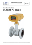
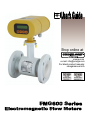
Induction flow meter FMG600 series
Page 1 of 44
Content
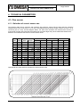
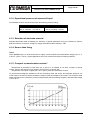
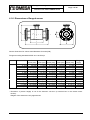
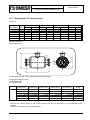
1. APPLICATION ............................................................................................................................................. 2 2. MEASUREMENT PRINCIPLE ..................................................................................................................... 2 3. TECHNICAL DESCRIPTION ....................................................................................................................... 3 3.1. GENERAL .................................................................................................................................................................. 3 3.2. METER DESIGN ........................................................................................................................................................... 3 3.2.1. Remote version ............................................................................................................................................... 3 3.2.2. Compact version .............................................................................................................................................. 4 4. TECHNICAL PARAMETERS....................................................................................................................... 5 4.1. FLOW SENSOR ............................................................................................................................................................ 5 4.1.1. Selection of correct sensor size ....................................................................................................................... 5 4.1.2. Operational pressure of measured liquid.......................................................................................................... 6 4.1.3. Selection of electrode material ......................................................................................................................... 6 4.1.4. Sensor tube lining............................................................................................................................................. 6 4.1.5. Compact or remote meter version? .................................................................................................................. 6 4.1.6. Dimensions of flanged sensor .......................................................................................................................... 7 4.1.7. Dimensions Tri Clover sensor .......................................................................................................................... 8 4.1.8. Flow sensor specifications ............................................................................................................................... 9 4.2. ELECTRONIC UNIT BOX ................................................................................................................................................ 9 4.2.1. Electronic unit specifications .......................................................................................................................... 10
5. METER APPLICATION RULES..............................................................................................................................................11
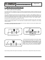
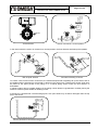
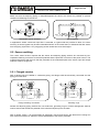
5.1. SENSOR PLACEMENT IN PIPING ................................................................................................................................... 11 5.2. SENSOR GROUNDING ................................................................................................................................................ 14 5.2.1. Flanged version .............................................................................................................................................. 14 5.2.2 Tri Clover ......................................................................................................................................................... 15 6. FLOW METER INSTALLATION AND OPERATIONAL START ............................................................... 16 6.1. SENSOR INSTALLATION .............................................................................................................................................. 16 6.2. ELECTRIC CONNECTIONS OF INDUCTION FLOW METER ................................................................................................... 17 6.2.1. Connection to power source .......................................................................................................................... 17 6.2.2. Output signal connections ............................................................................................................................. 18 6.3. CONNECTION BETWEEN SENSOR AND ELECTRONIC UNIT (REMOTE VERSION) ...................... 18 6.4. CONNECTION BETWEEN SENSOR AND ELECTRONIC UNIT (REMOTE METER VERSION, PROTECTION CLASS IP 68) .................. 19 6.5. OPERATIONAL START ................................................................................................................................................ 19 6.5.1 Operational start .............................................................................................................................................. 19 6.5.2. Operational data ............................................................................................................................................. 20 6.5.3.1. Display formats of aggregate values .......................................................................................................... 22 6.5.3.2. Data reset ................................................................................................................................................... 22 7. PROGRAMMING........................................................................................................................................ 23 7.1. PROGRAMMING OF THE BASIC MENU ITEMS .................................................................................................................. 24 7.1.1. Displayed data ............................................................................................................................................... 24 7.1.2. Samples ........................................................................................................................................................ 25 7.1.3. Analog output ................................................................................................................................................ 26 7.1.4. Output function .............................................................................................................................................. 29 7.1.5. Electrode cleaning .......................................................................................................................................... 34 7.1.6. Serial line ...................................................................................................................................................... 35 7.1.7. Production data ............................................................................................................................................. 37 7.1.8. Dose setting .................................................................................................................................................. 39 7.1.9. Zero setting ................................................................................................................................................... 40 7.1.10. 100 percent ................................................................................................................................................. 40 7.1.11. Exit .............................................................................................................................................................. 40 7.2. THE PARAMETER SETTING MENU ................................................................................................................................ 42 7.3. THE PRODUCTION DATA MENU ................................................................................................................................... 43 8. STANDARD TESTS ................................................................................................................................... 44 9. CALIBRATION AND VERIFICATION TESTS ........................................................................................... 44