1
Design, Assembly and Service Manual
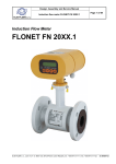
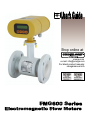
Induction flow meter FMG600 series
Page 3 of 44
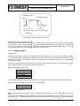
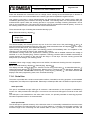
As the magnetic flux density and distance between the electrodes are constant, the induced voltage is
proportional to the liquid flow velocity in the tube. The value of the volume flow rate can then be readily
determined as a product of the flow velocity and square section of the tube, Q = v x S.
3. TECHNICAL DESCRIPTION
3.1. General
The induction flow meter consists of a sensor through which the measured liquid flows and an electronic unit
where the low-level signal from the sensor is modified to a standardized form suitable for further processing
in various industrial electronic devices. The output signal is proportional to the volume flow rate of the
measured liquid. The only factor limiting the application of induction flow meters is the requirement that the
measured liquid shall be conductive and non-magnetic. The induction flow meter can be designed either as
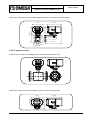
a compact device or with the sensor separated from the associated electronic unit. In the former case, the
electronic unit is fitted directly onto the meter sensor, in the latter case it is connected to the sensor by
special cable.
The sensor design shall take into consideration the type of the measured liquid and its operational
parameters. To facilitate fitting into the liquid piping, the sensor can be provided with end flanges, threaded,
or it maybe of a flangeless design. The supply voltage, types of output signal and communication interface
can be selected according to the customer requirements.
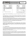
The basic configuration of induction flow meter includes two insulated passive binary outputs (each with
an opt coupler including a transistor output), insulated RS485 communications, dry relay, 4-20 mA output
and the USB communication interface. This USB interface is not insulated as it is used for factory calibration
purposes only. Optional accessories to this basic configuration are INPUT1 and OUTPUT3 for batching (all
with galvanic separation) –B, empty pipe detection -EPT.
Upon fastening the connecting wires into the respective terminals, make sure to tighten the bolts holding the
lid of the electronic unit and seal the cable glands. Fit blinds into the unused gland openings.
3.2. Meter design
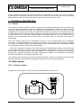
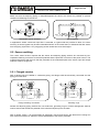
3.2.1. Remote version
Flanged sensor connected by a cable with the associated separate electronic unit.