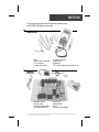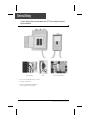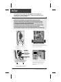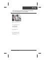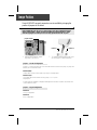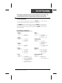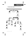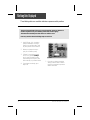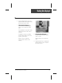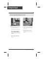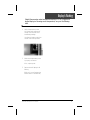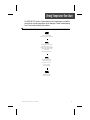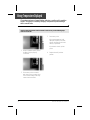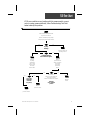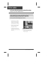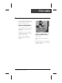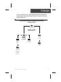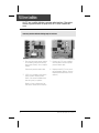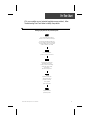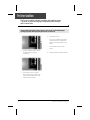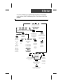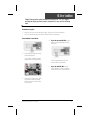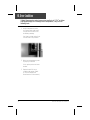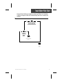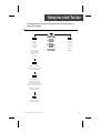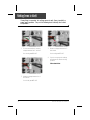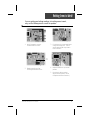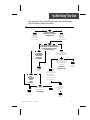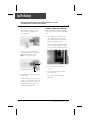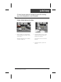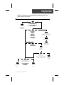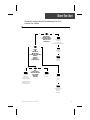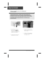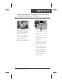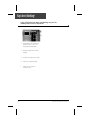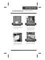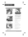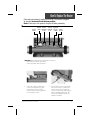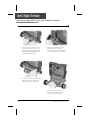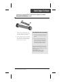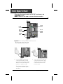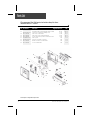
1
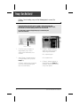
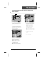
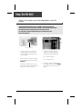
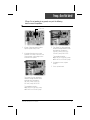
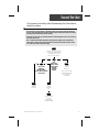
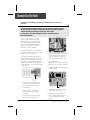
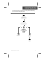
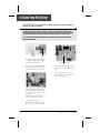
MSPA-MP METAPACK
SERVICE MANUAL
• Gecko Electronics Inc. •
Visual step-by-step guide to easily
identify & correct technical problems!
Table of Contents
Power & Ground Check
Tools and Parts
Electrical Wiring
GFCI Instructions & Flow Chart
3
4
5
Programming
Jumper Positions
Low Level Programming
8
9
Error Conditions
3 Flashing Dots Appearing On Keypad Display
3 Flashing Dots & LED Displayed
Display Is Flashing
Wrong Temperature Appearing On Keypad Display
FLO
FLC
Prr
HL
Smart Winter Mode
11
15
19
23
25
29
31
33
37
Troubleshooting
Nothing Seems to Work!
Spa Does Not Heat!
Pump 1/Pump 2 Does Not Work!
Blower Does Not Work!
Light Does Not Work!
Ozonator Does Not Work!
Circulation Pump Does Not Work!
Keys Do Not Work!
39
43
47
53
57
59
61
63
How to ...
Replace The Board
Replace The Heater (Horizontal Front/Back; Vertical/Side)
Adjust The Pressure Switch
65
67
73
Miscellaneous
Parts List
Wiring Diagrams
Professional Repair Kit Info
75
77
79
Note: For spa repairs and troubleshooting with Pocket-tek technology, please refer to
Pocket-tek User's Manual available from Gecko and at www.pocket-tek.com.
In an attempt to make this manual as useful as possible, it has been presented in two
formats. Problem-solving solutions are described with Troubleshooting Flow Charts
and also with Step-by-Step Procedures.
The two formats together should provide an overall complete explanation, with flow
charts providing an overview of specific problems, and step-by-step procedures giving
more detailed information.
Important Safety Information
WARNING: Risk of electrical shock! All procedures described in this service manual
must only be performed by qualified personnel, in accordance with the
standards applicable in the country of installation and, whenever
possible, with the equipment powered off. When connecting the
equipment, always refer to the wiring diagram affixed to the inside of
your spa pack’s power box cover! This diagram always prevails over
the wiring diagram at the end of this manual.
All information given subject to technical modifications without notice.
Tools & Parts
The tools, test equipment and components needed to carry
out MSPA-MP Metapack service calls.
Required tools:
Pliers
Phillips & flat screwdrivers
11/32" nut driver
1/4" open end wrench
3/8" open end wrench
Jumper cable
Multimeter
GFCI tester & digital thermometer (optional)
Required
pack parts:
Regulation sensor
Hi-Limit sensor
MSPA-MP system board
(or complete spa pack)
Transformer
Pressure switch
Fuses
Top side control (keypad)
Gecko Electronics Inc. sells Professionnal Repair Kits that include everything needed for MSPA-MP Metapack servicing.
For more information, go to the last page of this manual.
Electrical Wiring
Correct wiring of the electrical service box, GFCI box and pack terminal
block is essential.
Electrical Box
GFCI
Pack Terminal Block
1• Carry out a visual inspection to check
for signs of miswiring.
Refer to supplied wiring diagrams.
Call an electrician if necessary.
4
MSPA-MP Metapacks Service Manual
GFCI Flow Chart
If GFCI trips, follow Troubleshooting Flow Chart below to identify
the problem:
yes
no
Is GFCI
properly
connected?
yes
Verify
Wiring Diagram
and reconnect it.
no
Unplug
everything,
including
heater and light
cord wires.
Is GFCI
still tripping?
Reconnect
one component
at a time
until GFCI
starts to trip.
Replace
transformer.
Replace
defective
component.
yes
There is
a problem
with the
cable.
Call an
electrician.
no
If GFCI is
still tripping,
disconnect
the incoming
power line.
Replace
GFCI.
Is GFCI still
tripping?
Replace
board
if GFCI is
still tripping.
MSPA-MP Metapacks Service Manual
5
GFCI Trips!
If all connections are made, but nothing seems to be working, you
probably have a power supply problem. Carry out the following tests to
identify and correct the problem:
Note that for new installations, GFCI trippings due to miswiring are common.
If breaker is wired properly, GFCI trippings may occur when total amount of current
drawn by spa exceeds breaker rating. This is highly unlikely as each spa pack output
is individually fused, and fuses will blow before GFCI trips.
A current leak to ground will also cause GFCI to trip. If any of the components is faulty
and a leak of more than 5mA occurs, GFCI will trip to prevent electrocution.
There are different GFCI models on the market. Note that illustrations are examples only.
From electrical box
To spa
1• Verify if GFCI is properly
connected.
3• If GFCI is properly connected, but
still tripping, unplug all outputs including
heater and light cord wires.
Important
connections:
Neutral of GFCI
must be connected
to neutral bus.
Neutral from spa
must be connected
to breaker.
From electrical box
To spa
4• If GFCI still trips, replace transformer.
If it stops tripping, reconnect one
component at a time until GFCI
starts to trip. Replace defective
component.
2• If it is not, verify GFCI wiring
diagram and reconnect it.
6
MSPA-MP Metapacks Service Manual
GFCI Trips!
If GFCI continues to trip even after having replaced the transformer,
carry out the following tests to correct the problem:
1• Disconnect incoming power
lines.
If GFCI still trips, there must
be a cable problem.
Call an electrician!
2• If GFCI stops tripping,
replace GFCI.
3• If GFCI trips again, replace
board. (Refer to "How to
Replace the Board" section
of this manual.)
MSPA-MP Metapacks Service Manual
7
Jumper Positions
Certain MSPA-MP spa pack parameters can be modified by changing the
position of jumpers on the board.
Remove MSPA-MP power box cover to access jumpers. (See "How to Replace the Board"
section of this manual). Jumper functions may differ from information below. Please
check wiring diagram on inside pack cover to verify specific functions for our pack.
Jumper Location
Position 1
1• Jumpers are located in upper
right side of the board.
Position 2
2• To change a setting, simply pull cover
off and replace in desired position.
Jumper 1: Current Limiting Option
Jumper 1 is used to limit amount of current drawn when more than one pump (or pump and
blower) are on at the same time.
Position 1 (HC):
Heater will shut down if more than one pump is on at high speed.
Position 2 (LC):
The system will not turn heater on if any pump (1, 2 or 3) is on
at high speed.
"Heater" indicator will flash on display indicating that more heat is requested, but heater will
not be allowed to start.
Jumper 2: Keypad Configuration
Position 1:
10-key configuration.
Position 2:
8-key configuration.
8
MSPA-MP Metapacks Service Manual
Low Level Programming
Certain system operating parameters can be configured from the keypad. This
is normally done by Gecko or the spa installer, but may be done any time.
Low level programming:
To access low level programming, press and hold On/Off key for 20 seconds, after
which the first parameter code should appear on the display.
Use Up/Down keys to modify parameter values and On/Off key to change from
one parameter to the next. You must go through all parameters to exit this mode.
If you do not wish to change a parameter, simply press On/Off key to advance to
the next parameter.
List of parameter configurations
1- Pump 1
Display: P1 x
Value of x: 1 = single-speed
2 = two-speed
2- Pump 2
Display: P2 x
Value of x: 0 = not installed
1 = single-speed
2 = two-speed
6- Ozone
Display: O3 x
Value of x: 0 = not installed
1 = on only in filter cycle
2 = always on
3 = on with circ. pump
3- Pump 3
Display: P3 x
Value of x: 0 = not installed
1 = installed
7- Circulation pump
Display: CP x
Value of x: 0 = not installed
1 = regulated (with spa
temperature)
2 = always on
3 = on, except if 2 degrees
over set point
4- Blower
Display: bL x
Value of x: 0 = not installed
1 = single-speed
2 = two-speed
3 = three-speed
8- Filter cycle
Display: FC x
Value of x: 0 = filter cycle enabled
2 = filter cycle disabled
1 = filter cycle replaced
by purge cycle
5- Light
Display: LI x
Value of x: 0 = not installed
1 = 12 VAC (single-intensity)
2 = 12 VAC (triple-intensity)
3 = 120 VAC (single-intensity
on auxiliary 1 relay )
4 = Internal fiber box control
mode (2-aux. relay)
9- Pressure switch status
Display: PS x
Value of x: 0 = with Pump 1
1 = with circ. pump
(CP cannot be set to 0)
MSPA-MP Metapacks Service Manual
9
10
MSPA-MP Metapacks Service Manual
Flashing Dots Flow Chart
If 3 flashing dots appear on keypad display, follow Troubleshooting Flow
Chart below to identify the problem:
3 flashing dots appear on the display!
yes
no
Remove pack cover.
Is board LED on?
Make sure jumper is
set properly for
circulation pump and
reset breaker.
Follow
flashing dots
& LED flow chart.
Start Pump 1 (or
circulation pump if installed
by increasing set point).
yes
no
Do you have
continuity on your
voltmeter for
pressure switch?
yes
Verify
pressure
switch
connection.
Short pressure
switch terminals
with a jumper cable.
no
Disconnect
pressure switch
for 5 seconds
and reconnect it.
yes
Try to adjust
pressure switch.
Are dots still
flashing on
keypad display?
Replace pressure
switch cable.
no
Are dots still
flashing on
keypad display?
Replace pressure
switch cable.
Replace pressure
switch if problem
persists.
If problem persists,
replace board.
Remove anything
obstructing filter canister
or piping. Clear any air
locks. Verify water valves.
Try to adjust
pressure switch.
If problem persists,
replace board.
Replace pressure
switch if problem
persists.
MSPA-MP Metapacks Service Manual
11
Flashing Dots Displayed
Three flashing dots error condition indicates a pressure switch problem.
There must be enough water in the spa for normal operations. System may detect error
condition if spa filter is dirty or if something restricts flow of water in piping.
The heater will automatically shut down when error condition occurs.
Power may remain On when the following steps are carried out.
1• Verify if Pump 1 (or circulation
pump if installed) is working. If
pump is not working right, refer
to pump section of this manual.
2• Make sure jumper is set properly for circulation pump.
3• If Pump 1 is working properly,
turn it on by pressing Pump 1
key (or start circulation pump
by increasing the set point) and
test continuity on pressure switch.
4• If you detect continuity, go to
step #10.
12
5• If you do not detect continuity,
verify if pressure switch cable is
properly connected to pressure
switch and board.
MSPA-MP Metapacks Service Manual
Flashing Dots Displayed
6• Ensure adequate water flow in the
heater and short two pressure switch
terminals with jumper cable.
7• If the three dots disappear, first
make sure there is no blockage of
water or air lock and check water
valve.
If the installation is older than 2 years,
replace the pressure switch and recalibrate it.
If installation is recent, try readjusting the pressure switch. If this is not
possible, replace switch.
(Refer to "How to Adjust the
Pressure Switch" section of this
manual.)
MSPA-MP Metapacks Service Manual
8• If the three dots still appear, the
problem may be either with switch
cable or board.
Remove plastic cover and replace
cable.
9• Replace board if error condition still
persists. (Refer to "How to Replace
the Board" section.)
13
Flashing Dots Displayed
Power may remain On while the following steps are carried out.
10• If you have continuity on pressure
switch, follow these steps:
Disconnect pressure switch cable
for 5 seconds and reconnect it.
If error condition disappears, adjust pressure switch, if it is a new
installation (less than two years) or
replace it.
11• If error condition persists, remove
plastic cover and replace pressure
switch cable.
12• Replace board if error condition
still persists. (Refer to "How to
Replace the Board" section of this
manual.)
(Refer to "How to Adjust the
Pressure Switch" section of this
manual.)
14
MSPA-MP Metapacks Service Manual
Flashing dots and LED Flow Chart
If error condition occurs (potential Hi-Limit sensor or temperature probe
problem), follow Troubleshooting Flow Chart below to identify the problem:
Turn breaker off then on again to reset the system.
If Hi-Limit condition no longer persists,
check for blockage of water in the piping.
yes
no
Take water temperature
with a digital thermometer.
Are you getting correct
water temp. reading on the display?
yes
Verify if anything
is obstructing water
flow (closed traps or
dirty filters).
no
When error
condition occurs,
does heater
barrel feel hot?
Is HL probe
properly connected?
Clean pins, reconnect
it, and reset
the breaker.
Verify if
temperature probe
is touching water
or if cold air from
back can affect
reading.
If error condition
persists, replace probe
and reset breaker.
If error condition still
persists, replace board.
Verify if
temperature probe
is properly connected.
If so, replace probe
and reset breaker.
Replace
board if
error
condition
still persists.
MSPA-MP Metapacks Service Manual
15
Flashing Dots & LED Displayed
The three flashing dots and LED error condition is related to the Hi-Limit sensor
or temperature probe.
Turn breaker off then on again to reset the system.
If 3 flashing dots and LED disappear, wait until they are displayed again on keypad.
Power may remain On.
1• Take water temperature with a
digital thermometer.
c- If error condition persists, replace probe and reset breaker.
2• If keypad display shows correct
temperature:
a- Check if heater barrel feels hot.
d- If problem is not corrected,
replace board. (Refer to "How
to Replace Board" section of
present manual.)
If it's hot, verify if anything is
obstructing the flow of water
(closed valves or dirty filter).
3• Proceed to following page if
keypad display shows incorrect
temperature.
b- If it's not, verify if hi-limit probe
is properly connected.
Try to clean probe connector
pins. Even a small coating of film
can cause a bad connection.
Reconnect probe and reset
breaker.
16
MSPA-MP Metapacks Service Manual
Flashing Dots & LED Displayed
If keypad display isn't showing correct temperature, carry out the
following tests:
1• Verify if temperature probe
is in contact with water and if
cold air from the back could
be affecting readings.
Use foam to isolate probe from
cold air if that is the problem.
2• Make sure temperature probe
is properly connected.
If it is, replace probe and reset
breaker.
3• Replace board if error condition
still persists. (Refer to "How to
Replace the Board" section of
this manual.)
MSPA-MP Metapacks Service Manual
17
18
MSPA-MP Metapacks Service Manual
Display Flashing Flow Chart
On MSPA-MP-NE packs, if system detects temperature at 112°F or
higher, the display will start flashing. Follow Troubleshooting Flow Chart
below to identify the problem:
yes
no
Press
any key.
A power failure
has occurred.
Has display
stopped flashing?
System
works fine.
yes
no
Are you getting correct
water temp. reading on the display?
yes
no
Is weather
very hot?
Verify if
temperature probe
is touching water
or if cold air from
back can affect
reading.
If so, replace probe
and reset breaker.
Remove
spa cover
(even during
the night).
Start
blower, if
spa is
equipped
with one.
yes
Replace
board.
Wait until
spa cools
down (add
cold water
if needed).
MSPA-MP Metapacks Service Manual
Verify if
temperature probe
is properly connected.
Replace
board if
problem
still persists.
no
Lower set point
below actual
temperature of
water.
"Heater" indicator
on keypad display
should disappear.
Do you get a
240 VAC reading
between
two heater wires
on the board?
Pump is
overheating
water during
filter cycle.
Lower
filter cycle
duration.
19
Display Is Flashing
If digital thermometer water temperature reading is 112°F or higher and
keypad display indicates correct temperature, carry out the following
tests:
If display stops flashing after pressing a key, this means that a power failure has occurred.
System works fine.
If weather is very hot:
1• Remove spa cover (even during
the night). Start blower if spa is
equipped with one. Wait until
spa cools down (add cold water
if necessary).
If hot weather is not a factor:
4• If you do not read 240 VAC, pump
may be overheating water during
filter cycle.
Enter Programming mode and
shorten filter cycle duration.
5• If you do read 240 VAC, test the
element. If it is opened, replace
it. If element works fine, replace
board.
(Refer to "How to Replace the
Board" section of this manual.)
2• Lower set point below current
water temperature.
"Heater" indicator should disappear
from keypad display.
3• Remove spa cover. With a voltmeter, read the voltage between
the two heater wires on the board.
20
MSPA-MP Metapacks Service Manual
Display Is Flashing
If digital thermometer water temperature reading is 112°F or higher and
keypad display isn't showing correct temperature, carry out the following
tests:
1• Verify if temperature probe
is in contact with water and if
cold air from the back could
be affecting readings.
Use foam to isolate probe from
cold air if that is the problem.
2• Make sure temperature probe
is properly connected.
If it is, replace probe.
3• Replace board if display is still
flashing.
(Refer to "How to Replace the
Board" section of this manual.)
MSPA-MP Metapacks Service Manual
21
22
MSPA-MP Metapacks Service Manual
Wrong Temperature Flow Chart
On MSPA-MP-NE packs, if system detects that temperature is not within
normal limits, wrong temperature will be displayed. Follow Troubleshooting
Flow Chart below to identify the problem:
Check if regulation
probe is properly connected.
Unplug probe connector
and clean pins on the
board (even a small coating
of film may cause a bad
connection).
Reconnect the probe.
Replace probe with
a spare and verify if
problem is solved.
If it is, replace
probe with spare.
Replace board if
problem persists.
MSPA-MP Metapacks Service Manual
23
Wrong Temperature Displayed
Wrong temperature on keypad display indicates a problem with regulation
sensor. The system is constantly verifying if temperature probe reading is
within normal limits.
Note that water temperature must be over 35°F in order to carry out the following steps.
Power can remain On.
3• Reconnect probe.
If wrong temperature is still
displayed, replace probe with
a spare and place probe head
directly in spa water.
If problem is solved, replace
probe.
1• Verify if regulation probe (sensor
located in spa) is properly
connected.
4• Replace board if problem
persists.
2• Disconnect probe connector
and clean probe connector pins.
Even a small coating of film may
cause a bad connection.
24
MSPA-MP Metapacks Service Manual
FLO Flow Chart
If FLO error condition occurs (problem with the pressure switch: pump is
on but no water pressure detected), follow Troubleshooting Flow Chart
below to identify the problem:
There must be adequate water
in spa for normal use.
Ensure circulation pump jumper
is set properly (see Jumper Section).
yes
no
Is pump
working?
Refer to "Pump not
Working" section.
yes
no
Is anything limiting
flow of water into pipes?
Remove
anything
obstructing
filter. Clear
any air locks
and verify
water valves.
Verify if
pressure switch
cable is properly
connected
to pressure
switch and
board.
yes
yes
no
Is it a new
installation
(less than
two years)?
no
Ensure flow of
water through heater and
short two pressure
switch terminals with a jumper.
Does FLO
error condition
persist?
Replace
board.
Replace
pressure switch.
Adjust
pressure switch.
MSPA-MP Metapacks Service Manual
25
FLO Error Condition
An FLO error condition indicates a pressure switch problem. If system
does not detect any pressure when pump is manually or automatically
turned on, an FLO error condition will occur.
There must be enough water in the spa for normal operations. System may detect an FLO error
condition if spa filter is dirty or if something restricts flow of water in piping.
The heater will automatically shut down when an FLO error condition occurs.
Power may remain On when the following steps are carried out.
1• Verify if pump (or circulation
pump if present) is working.
If pump is not working right,
refer to pump (or circulation
pump) section of this manual.
2• Make sure jumper setting for
circulation pump is correct.
(See Jumper Section).
3• Clean filter and check for air
blockages, closed trap valves or
anything that could be restricting
water flow.
26
4• Verify if pressure switch cable is
properly connected to pressure
switch and board.
MSPA-MP Metapacks Service Manual
FLO Error Condition
5• Ensure adequate water flow in the
heater and short two pressure switch
terminals with jumper cable.
6• If FLO error condition disappears,
perform the following steps:
If the installation is older than 2 years,
replace the pressure switch and recalibrate it.
If installation is recent, try readjusting the pressure switch. If this is not
possible, replace switch.
(Refer to "How to Adjust the
Pressure Switch" section of this
manual.)
7• If FLO error condition persists, the
problem may be either with switch
cable or board.
Remove plastic cover and replace
cable.
8• Replace board if FLO error condition
still persists. (Refer to "How to Replace
the Board" section.)
MSPA-MP Metapacks Service Manual
27
28
MSPA-MP Metapacks Service Manual
FLC Flow Chart
If FLC error condition occurs, follow Troubleshooting Flow Chart below to
identify problem (usually pressure switch problem - pump is off but water
pressure is detected):
First ensure jumper position for circulation pump is set correctly
(see Jumper Section).
yes
no
Disconnect
pressure switch cable.
Does FLO error condition
occur when pump is on?
yes
no
Is it a new
installation
(less than
two years)?
Adjust
pressure
switch.
Replace
pressure
switch cable.
Replace
pressure switch.
Replace
board.
Replace
pressure switch
if FLC error
condition
persists when
you start or
stop pump.
MSPA-MP Metapacks Service Manual
29
FLC Error Condition
An FLC error condition indicates a pressure switch problem. If the system
detects any pressure when the pump is off, an FLC error condition will
occur.
Power may remain On while the following steps are carried out.
1• First check to ensure jumper position
for circulation pump is set correctly
(see Jumper Section). If not, readjust
jumper.
3• If there is no FLO error condition,
remove plastic cover and replace
pressure switch cable.
Disconnect pressure switch cable.
4• Replace board if FLC error condition still persists. (Refer to "How to
Replace the Board" section of this
manual.)
2• If FLO error condition occurs when
pump is started, adjust pressure
switch, if it is a new installation (less
than two years) or replace it.
(Refer to "How to Adjust the Pressure Switch" section of this manual.)
30
MSPA-MP Metapacks Service Manual
Prr Flow Chart
If Prr error condition occurs (potential regulation sensor problem), follow
Troubleshooting Flow Chart below to identify the problem:
Pressing any key after each step resets the system.
Note that water temperature
must be over 35°F to operate spa.
In systems manufactured after 98,
Prr error status is ignored during first
hour after initial power up to allow
water to heat to over 35°F.
Check if regulation
probe is properly connected.
Unplug probe connector
and clean pins on the
board (even a small coating
of film may cause a bad
connection).
Reconnect the probe.
Replace probe with
a spare and verify if
problem is solved.
If it is, replace
probe with spare.
Replace board if
problem persists.
MSPA-MP Metapacks Service Manual
31
Prr Error Condition
The Prr error condition indicates a problem with regulation sensor.
The system is constantly verifying if temperature probe reading is
within normal limits.
Note that water temperature must be over 35°F in order to carry out the following steps.
Pressing any key after each step resets system. Power can remain On.
3• Reconnect probe.
If Prr error condition still persists,
replace probe with a spare and
place probe head directly in spa
water.
If problem is solved, replace
probe.
1• Verify if regulation probe (sensor
located in spa) is properly
connected.
4• Replace board if problem persists.
2• Disconnect probe connector
and clean probe connector pins.
Even a small coating of film may
cause a bad connection.
32
MSPA-MP Metapacks Service Manual
HL Flow Chart
If HL error condition occurs (potential Hi-Limit sensor or temperature
probe problem), follow Troubleshooting Flow Chart below to identify the
problem:
Turn breaker off then on again to reset the system.
yes
no
Take water temperature
with a digital thermometer.
yes
no
Is water temperature
112°F or higher?
Are you getting correct
water temp. reading on the display?
yes
no
Is weather
very hot?
Remove
spa cover
(even during
the night).
Start
blower, if
spa is
equipped
with one.
Wait until
spa cools
down (add
cold water
if needed).
Verify if
temperature probe
is touching water
or if cold air from
back can affect
reading.
yes
Replace
board.
no
Lower set point
below actual
temperature of
water.
Verify if
temperature probe
is properly connected.
If so, replace probe
and reset breaker.
Pump is
overheating
water during
filter cycle.
"Heater" indicator
on keypad display
should disappear.
Lower
filter cycle
duration.
Do you get a
240 VAC reading
between
two heater wires
on the board?
Replace
board if
HL error
condition
still persists.
yes
Verify if anything
is obstructing water
flow (closed traps or
dirty filters).
no
When HL error
condition occurs,
does heater
barrel feel hot?
If HL error condition
persists, replace probe
and reset breaker.
If HL error condition still
persists, replace board.
Is HL probe
properly
connected?
Clean pins,
reconnect
it, and reset
the breaker.
HL Error Condition
The HL error condition is related to the Hi-Limit sensor or
temperature probe.
Turn breaker off then on again to reset the system.
Power may remain On.
1• Take water temperature with a
digital thermometer.
c- If HL error condition continues
to appear on display, replace
probe and reset breaker.
2• If reading is below 112°F, HL
error condition should be steady,
indicating a problem at the hi-limit
probe and heater level.
d- If problem is not corrected,
replace board. (Refer to "How
to Replace Board" section of
this manual.)
a- Check if heater barrel feels hot.
If it's hot, verify if anything is obstructing the flow of water (closed
valves or dirty filter).
b- If it's not, verify if hi-limit probe is
properly connected.
3• If reading is 112°F or higher,
HL error condition should
flash, indicating a problem with
temperature probe.
Proceed to following page if
keypad display shows correct
temperature.
Proceed to page 36 if display
doesn't show correct temperature.
Try to clean probe connector pins.
Even a small coating of film can
cause a bad connection. Reconnect probe and reset breaker.
34
MSPA-MP Metapacks Service Manual
HL Error Condition
If digital thermometer water temperature reading is at 112°F or higher
and keypad display indicates correct temperature, carry out the following
tests:
If weather is very hot:
1• Remove spa cover (even during the night). Start blower if spa is equipped
with one. Wait until spa cools down (add cold water if necessary).
If hot weather is not a factor:
4• If you do not read 240 VAC, pump
may be overheating water during
filter cycle.
2• Lower set point below current
water temperature.
The "Heater" indicator should
disappear from keypad display.
Enter Programming mode and
shorten filter cycle duration.
5• If you do read 240 VAC, replace
board. (Refer to "How to Replace
the Board" section of this manual.)
3• Remove the plastic cover. With
a voltmeter, read the voltage
between the two heater wires
on the board.
MSPA-MP Metapacks Service Manual
35
HL Error Condition
If digital thermometer water temperature reading is at 112°F or higher
and keypad display isn't showing correct temperature, carry out the
following tests:
1• Verify if temperature probe
is in contact with water and if
cold air from the back could
be affecting readings.
Use foam to isolate probe from
cold air if that is the problem.
2• Make sure temperature probe
is properly connected.
If it is, replace probe and reset
breaker.
3• Replace board if HL error
condition still persists. (Refer
to "How to Replace the
Board" section of this manual.)
36
MSPA-MP Metapacks Service Manual
Smart Winter Mode Chart
If pumps have started up on several occasions and "Filter Cycle" indicator
is flashing on keypad, follow this Troubleshooting Flow Chart to identify the
problem:
yes
no
Is the water temperature
of the spa lower than
the desired temperature?
yes
no
Do you
read 240 VAC
to the
heater?
Refer to
"Spa not heating"
section.
System
works
fine.
MSPA-MP Metapacks Service Manual
37
Smart Winter Mode
If pumps have started up several times and "Filter Cycle" indicator is
flashing, the system has detected water cold enough to freeze the pipes
and has gone into the protective Smart Winter Mode.
An irregularly flashing "Filter Cycle" indicator means that the system has stopped filtering after
3 hours because water temperature exceeds set point by more than 2˚F. If the temperature
cools down before the scheduled end of the cycle, filtering will resume for the remainder of the
programmed cycle duration.
1• With a digital thermometer, verify
the temperature of the water.
2• If the water temperature is lower than
the desired temperature, measure the
voltage to the heater.
If your reading is approx. ≈240 VAC,
Smart Winter Mode is working properly.
If you do not read ≈240 VAC, refer to
the "Spa not heating" section of this
manual.
38
MSPA-MP Metapacks Service Manual
"Nothing Seems to Work" Flow Chart
If nothing seems to work, follow Troubleshooting Flow Chart below to
identify the problem:
yes
Verify if
keypad is
connected
correctly
to board.
All eight pins
must be plugged in
and black wire
must be on top
of the plug.
no
Do you get a
≈240 VAC reading
between
line 1 & line 2,
≈120 VAC
between
line 1 & neutral,
≈120 VAC
between
line 2 & neutral
on the board?
There is
an electrical
wiring
problem.
Call an
electrician.
Replace transformer
fuse if there is still nothing on
the keypad display.
If nothing still works,
clean the transformer
orange connector pins
(even a small coating of film may
cause a bad connection).
Replace transformer if
problem persists.
Replace board if
problem still persists.
MSPA-MP Metapacks Service Manual
39
Nothing Seems to Work!
If everything is connected, but nothing seems to work, there is probably a
power supply problem. Carry out the following tests to identify and correct
the problem:
1• On the terminal block, measure
voltage between line 1 and line 2.
You should get ≈240 VAC.
3• Measure voltage between line 2
and neutral.
You should get ≈120 VAC.
4• If you do not get good readings,
this indicates an electrical wiring
problem.
Call an electrician!
2• Measure voltage between line 1
and neutral.
You should get ≈120 VAC.
40
MSPA-MP Metapacks Service Manual
Nothing Seems to Work!
If you are getting good voltage readings, but nothing seems to work,
carry out the following tests to correct the problem:
1• Verify if keypad is correctly
connected to the board.
3• If nothing works, clean transformer
orange connector pins. Even a
small coating of film may cause a
bad connection.
Xfo
fuse
2• Replace transformer fuse
if nothing still seems to work.
4• Replace transformer if problem
persists.
5• If problem is still not solved,
replace board. (Refer to "How
to Replace the Board" section.)
MSPA-MP Metapacks Service Manual
41
42
MSPA-MP Metapacks Service Manual
"Spa Not Heating" Flow Chart
If the spa does not seem to be heating the water, follow Troubleshooting
Flow Chart below to identify the problem:
yes
Refer to
specific section
referred to
error condition.
no
Any error conditions
(flashing dots, FLO, FLC, etc.)
on keypad display?
yes
Ensure temp.
set point is
higher than
actual water temp.
no
Has "Heater" indicator appeared on
keypad display? (If "Heater" indicator is
flashing, system is in LC mode.
See Jumper section.)
yes
no
Make sure system
Can you read
is not in Economy mode
240 VAC between
(10-key keypad only).
two terminals
of the heater
yes
no
on the board?
Take water temperature
and compare with
temp. value displayed
on keypad.
Is difference
greater than ±2°F?
Replace
board.
yes
no
Are
heater wires
connected
correctly
to the
element?
System
works fine.
Is temperature
probe touching water
or hot air rear
affecting reading?
Isolate back of
probe with foam.
yes
no
Try tightening wires
to the board & element.
Replace
temperature probe
with spare.
Still not heating?
Replace
element.
Replace
board.
MSPA-MP Metapacks Service Manual
43
Spa Not Heating!
If the spa does not appear to be heating the water, carry out
the following tests to correct the problem:
1• Check for an error condition on
keypad display. If there is one,
refer to section indicated by the
error condition.
If "Heater" indicator does not light up!
Make sure system is not in an Economy
mode cycle (10-key keypad configuration
only).
4• Use a digital thermometer to take
water temperature and compare
your reading with the temperature
value on the keypad display.
If values are different (±2°F), verify if
sensor is touching water or if hot air
from rear could be affecting readings.
2• If there is no error condition try
to increase temperature by raising
temperature set point. Press
Up key to increase set point.
"Set
Point"
icon
5• If yes, use foam to isolate behind
the probe.
"Heater"
indicator
3• Verify if "Heater" indicator appears
on the display.
6• If no, replace temperature sensor
with a spare one.
7• If spa is still not heating, replace
the board.
"Heater" indicator will be on when
heater is on. It will flash if more heat
has been requested, but heater has
not yet started or if system is in LC
mode (see Jumper Section).
44
MSPA-MP Metapacks Service Manual
Spa Not Heating!
If "Heater" indicator appears on the display, but spa is still not heating,
carry out the following tests to correct the problem:
If "Heater" indicator lights up on the display:
1• Remove plastic cover and measure
voltage between two heater screws
on the board.
2• If voltage reading is correct, verify
if heater wires are properly connected to the element.
Replace board if you are not getting
a reading of ≈240 VAC.
If not, tighten wires to board and
element.
3• If problem persists, replace the
element.
MSPA-MP Metapacks Service Manual
45
46
MSPA-MP Metapacks Service Manual
Pump Flow Chart
If Pump 1 or Pump 2 is not working, follow Troubleshooting Flow Chart
below to identify the problem:
yes
Refer to
specific section
indicated by
error condition.
no
Have any error
conditions (flashing dots,
FLO, FLC, etc.) appeared on
keypad display?
yes
no
Does Pump 1
or Pump 2
indicator
appear on
keypad display
when you
press Pump 1 or
Pump 2 key?
Verify if low level
programming is set correctly
(see Low Level Section).
Replace keypad.
yes
no
If still not working,
replace board.
Do pumps work
in either speed?
Verify
low level
programming.
yes
no
Replace Pump 1 or
Pump 2 fuse.
Pump(s) still not working!
yes
no
Problem
resolved.
Measure voltage
on the board for both speeds.
Replace Pump 1
or Pump 2.
Do you get 240 VAC
reading for
both speeds?
MSPA-MP Metapacks Service Manual
Replace
board.
47
Pump 1 Does Not Work!
If Pump 1 is not working, carry out the following tests to correct the
problem:
To increase the life of the relay, we use a "snubber" circuit on the pump relay.
With this type of circuit, if no pump is connected to an output and relays are open,
the voltmeter will continue reading around 60 volts. This is normal.
It is important to measure voltage when pump is connected to pack.
Power must remain On.
"Pump 1" indicator
1• Check for an error condition on
keypad display. If yes, refer to
specific section indicated by error
condition.
3• If "Pump 1" indicator does not
appear, use a spare keypad to
verify if keypad is defective.
If it is, replace keypad.
2• Verify if "Pump 1" indicator appears
on keypad display when you press
Pump 1 key.
If "Pump 1" indicator does not appear,
check low level programming first
(see Low Level Section).
48
If not, replace board.
4• If "Pump 1" indicator appears on
keypad display when Pump 1 key
is pressed, verify if Pump 1 works
in any of the speeds.
MSPA-MP Metapacks Service Manual
Pump 1 Does Not Work!
If Pump1 does not work in any speed, carry out the following tests to
correct the problem:
Pump 1 fuse
1• If Pump 1 does not work in either
speed, replace Pump 1 fuse.
2• If replacing the fuse does not work,
or if Pump 1 works in one of two
speeds, take voltage reading on the
board for both speeds.
3• Turn Pump 1 to high speed and
measure voltage between white
and red wire connectors:
240 VAC pump: P57& P37
120 VAC pump: P48 & P37
The reading shoud be:
≈240 VAC for a 240 VAC pump
≈120 VAC for a 120 VAC pump
4• If voltage is correct, replace
Pump 1.
5• If not, replace board.
Turn Pump 1 to low speed and
measure voltage between white
and black wire connectors:
240 VAC pump: P57 & P64
120 VAC pump: P48 & P64
The reading shoud be:
≈240 VAC for a 240 VAC pump
≈120 VAC for a 120 VAC pump
MSPA-MP Metapacks Service Manual
49
Pump 2 Does Not Work!
If Pump 2 is not working, carry out the following tests to correct the
problem:
To increase the life of the relay, we use a "snubber" circuit on the pump relay.
With this type of circuit, if no pump is connected to an output and relays are open,
the voltmeter will get a reading of around 60 volts. This is normal.
It is important to measure voltage when pump is connected to the pack.
Power must remain On.
"Pump 2" indicator
1• Check for any error condition on
keypad display. If there are, refer
to specific section indicated by the
error condition.
3• If "Pump 2" indicator does not
appear, use a spare keypad to
verify if spa keypad is defective.
If it is, replace keypad.
2• Verify if "Pump 2" indicator appears
on keypad display when you press
Pump 2 key.
If "Pump 2" indicator does not appear, check low level programming
first (see Low Level Section).
50
If not, replace board.
4• If "Pump 2" indicator appears on
the display when you press Pump 2
key, verify if Pump 2 works in any
speed.
MSPA-MP Metapacks Service Manual
Pump 2 Does Not Work!
If Pump 2 is not working in any speed, carry out the following
tests to correct the problem:
Pump 2 fuse
1• If Pump 2 does not work in either
speed, replace Pump 2 fuse.
2• If replacing fuse does not correct
problem, or if Pump 2 works in one
of two speeds, read voltage on the
board for both speeds.
3• Turn Pump 2 to high speed and
measure voltage between white
and red wire connectors:
240 VAC pump: P58 & P22
120 VAC pump: P45 & P22
The reading shoud be:
≈240 VAC for a 240 VAC pump
≈120 VAC for a 120 VAC pump
4• If voltage is correct, replace
Pump 2.
5• If not, replace board.
Turn pump 2 to low speed and
measure voltage between white
and black wire connectors:
240 VAC pump: P58 & P35
120 VAC pump: P45 & P35
The reading shoud be:
≈240 VAC for a 240 VAC pump
≈120 VAC for a120 VAC pump
MSPA-MP Metapacks Service Manual
51
52
MSPA-MP Metapacks Service Manual
Blower Flow Chart
If blower isn't working, follow this Troubleshooting Flow Chart
to identify the problem:
yes
no
Does "Blower"
indicator appear
on keyboard display
when you press
Blower key?
yes
no
Do you
read
≈120 VAC for
120 VAC blower
(or ≈240 VAC for 240 VAC)
at blower
output on
the board
(in high speed)?
yes
It's possible
that blower
is not getting
enough air entry.
Verify blower
low level
programming
(see Low Level Section).
Replace
keypad.
Replace
board.
no
Does
blower restart
after a few minutes
(to cool down
after being
shut off)?
Replace
blower.
Replace
blower
fuse.
Create an opening
to allow more air
under spa skirt.
Replace board
if blower
still does
not start.
MSPA-MP Metapacks Service Manual
53
Blower Does Not Work!
If blower is not working, carry out the following tests
to correct problem:
To increase the life of the relay, a "snubber" circuit is used on the blower relay.
With this type of circuit, if no blower is connected to an output and relays are open,
the voltmeter will continue to get a voltage reading of around 60 volts. This is normal.
It is important to measure voltage when the blower is connected to the pack.
Power must remain On.
Blower
indicator
1• Verify if "Blower" indicator
lights up on keypad display
when you press Blower key
(triangular icon will flash when
blower is in low speed).
2• Verify if blower low level programming is set correctly.
54
3• If "Blower" indicator does not
appear on keypad display, then
replace keypad.
4• If "Blower" indicator still does
not appear on keypad display,
then replace board.
MSPA-MP Metapacks Service Manual
Blower Does Not Work!
If "Blower" indicator lights up on control display, but blower still isn't working,
carry out the following tests to correct the problem:
1• If indicator lights up on keypad
while blower is in high speed,
take voltage reading between
white and black wire connectors:
240 VAC blower: P59 & P43
120 VAC blower: P49 & P43
Your reading should be:
≈240 VAC for a 240 VAC blower
≈120 VAC for a 120 VAC blower
Blower fuse
2• Replace blower fuse if you do
not get a high enough voltage
reading.
3• Replace board if you still aren't
getting a voltage reading.
(Refer to "How to Replace the
Board" section.)
4• If you do get a good voltage
reading, check if you can restart
blower a few minutes after
being turned off.
Replace blower if it does not
start after cool down period.
5• If blower does start up after
cool down, it's possible that it
is not drawing in enough air.
6• Enlarge the opening to allow
more air into blower.
MSPA-MP Metapacks Service Manual
55
56
MSPA-MP Metapacks Service Manual
Spa Light Flow Chart
If spa light does not appear to be working, follow Troubleshooting
Flow Chart below to identify the problem:
no
yes
Have you
tried replacing
the spa
light bulb?
yes
yes
no
Try replacing
light bulb.
Is light
still not
lighting
up?
no
Does "Light"
indicator
appear on
keypad
display when
you press
Light key?
Verify low level
programming
(see Low Level Section).
Replace
keypad.
If "Light" indicator still
does not appear on display,
replace board.
yes
Replace spa
light socket.
no
Do you get a
12 VAC reading
on light ouput
on board
when light is
on at highest
intensity
(steady indicator
light)?
Replace spa
light fuse.
Replace board if
light is still not working.
MSPA-MP Metapacks Service Manual
57
Spa Light Does Not Work!
If spa light is not working, carry out the following tests
to correct the problem:
It is important to measure voltage when light is connected to the pack.
Power must remain On.
1• The first step is to try replacing
the spa's light bulb.
"Light"
indicator
2• If light still isn't working, verify if
"Light" indicator appears on
keypad display when you press
Light key.
4• If "Light" indicator appears, but
light still isn't working, make sure
light is at highest intensity setting
(indicator solid light, not flashing),
remove plastic cover and measure
voltage between opposite prongs
of connector P14 on the board.
If you get ≈12 VAC, replace light
socket.
Light fuse
3• If "Light" indicator doesn't appear,
(verify low level programming first,
see Low Level Section) use a spare
keypad to verify if spa keypad is
defective.
If it is, replace keypad.
If not, replace board.
5• If you aren't getting a voltage reading, replace light fuse on the board.
6• If the problem persists, replace
board. (Refer to "How to Replace
the Board" section.)
58
MSPA-MP Metapacks Service Manual
Ozonator Flow Chart
If the ozonator is not working, follow Troubleshooting Flow Chart below to
identify the problem:
If the user turns on a pump, blower or light during a filter cycle, the cycle will be interrupted and
will only resume 40 minutes after last active output has been turned off (automatically or manually).
This delay is to prevent excessive ozonator activation.
During this interval, "Filter cycle" indicator will flash in a different sequence (On: 1/2 sec., Off: 1/2 sec.,
On: 1/2 sec., Off: 1 1/2 sec.).
Also, to prevent excessive water temperature caused by overly long filter cycles, the system will
cancel a filter cycle after 3 hours if water temperature rises more than 2°F above set point. In this
case, "Filter Cycle" indicator flashes on display.
Verify low level programming
to make sure that ozonator
is programmed properly
(see Low Level Section).
no
yes
yes
no
Do you read
120 VAC for
120 VAC ozonator
(or 240 VAC for 240 VAC)
on the board?
Replace
ozonator.
Has
"Filter Cycle"
indicator (steady
indicator light)
appeared
on keypad
display?
Start up
filter cycle.
"Filter Cycle" indicator
(steady indicator light)
should light up
on display.
Replace
ozonator
fuse.
Replace board
if you still
aren't getting
a voltage reading.
MSPA-MP Metapacks Service Manual
59
Ozonator Does Not Work!
If ozonator isn't working, carry out the following tests to correct the
problem:
To increase the life of the relay, a "snubber" circuit is used on the ozonator relay. With
this type of circuit, if no ozonator is connected to an output and relays are open, the
voltmeter will still get a reading of around 60 volts. This is normal.
It is important to take voltage reading with ozonator connected to the pack.
Power must remain On.
N.B.: On new systems, if a pump,
blower or light is turned on during
filter cycle, the cycle will be interrupted and will resume only 40 minutes
after the last active output has been
turned off. This delay is to prevent
excessive ozonator activation.
During this time, "Filter Cycle" indicator
will flash in a different sequence (3 short,
1 long, 3 short, 1 long, etc.).
To prevent excessive water temperature due to overly long filter cycles, the
system will automatically cancel a filter
cycle after 3 hours if water temperature
climbs more than 2°F above set point.
In this case, "Filter Cycle" indicator flashes
on the display.
3• Measure voltage between ozonator
white and black wire connectors:
240 VAC ozonator: P60& P30
120 VAC ozonator: P46 & P30
You should read:
≈240 VAC for a 240 VAC ozonator
≈120 VAC for a 120 VAC ozonator
4• Replace ozonator if you get a good
voltage reading.
"Filter Cycle"
indicator
1• Verify low level programming to
make sure that ozonator is programmed properly (see Low
Level section).
2• Verify if "Filter Cycle" indicator
(steady indicator light) appears
on keypad.
If not, start up a filter cycle (refer
to MSPA-MP User's Manual).
60
Ozonator
fuse
5• Replace ozonator fuse if voltage
reading isn't high enough.
6• Replace board if you still don't
get a voltage reading. (Refer to
"How to Replace the Board"
section.)
MSPA-MP Metapacks Service Manual
Circulation Pump Flow Chart
If circulation pump does not appear to be working, follow Troubleshooting
Flow Chart below to identify the problem:
Verify if low level
programming has been
programmed properly
(see Low Level Section).
Increase set point to
2° above actual water temp.
to start circulation pump.
yes
no
Do you
read
≈120 VAC for
120 VAC circ. pump
(or ≈240 VAC for 240 VAC)
at circ. pump
output on
the board?
Replace
circulation pump.
Replace
circulation
pump fuse.
Replace
board.
MSPA-MP Metapacks Service Manual
61
Circulation Pump Not Working!
If your MSPA-MP has a defective circulation pump, carry out the following
tests to correct the problem:
To increase the life of the relay, a "snubber" circuit is used on the circulation pump relay.
With this type of circuit, even if no circulation pump is connected to an output and relays
are open, the voltmeter will continue to get a volt reading around 60. This is normal.
It is important to take voltage reading when circulation pump is connected to the pack.
Power must remain On.
"Set Point"
icon
1• Verify if low level programming
has been programmed properly
(see Low Level Section).
2• Start circulation pump by setting
temperature set point 2° higher
than actual water temperature.
Circulation pump fuse
4• If you don't get a voltage reading,
replace board's circulation pump
fuse.
5• If problem persists, replace the
board. (Refer to "How to Replace
the Board" section.)
3• Remove plastic cover and take
voltage reading between circulation pump's black and white wire
connectors.
240 VAC pump: P36 & P54
120 VAC pump: P36 & P41
The reading shoud be:
≈ 240 VAC for 240 VAC pump
≈ 120 VAC for 120 VAC pump
62
MSPA-MP Metapacks Service Manual
Keys Flow Chart
If any of the keys on the keypad display do not seem to be working, follow
Troubleshooting Flow Chart below to identify the problem:
Verify Jumper #2.
Make sure system is set
for a 8- or 10-key
keypad configuration.
Unplug keypad
and replace
with spare
keypad.
yes
no
Are keys
working?
Replace
keypad.
MSPA-MP Metapacks Service Manual
Replace
board.
63
Keys Aren't Working!
If any of the keys do not seem to be working, carry out the
following tests to correct the problem:
1• Verify Jumper #2. Make sure
system is set for a 8- or 10key keypad configuration.
2• Replace keypad with a spare
keypad.
3• Verify if keys respond correctly.
4• If they do, replace keypad.
5• If they do not respond,
replace board.
64
MSPA-MP Metapacks Service Manual
How To Replace The Board
When replacing an MSPA-MP board, it is important to make sure
to turn power off before proceeding.
1• Loosen 4 screws holding spa pack
cover and remove. Disconnect
power input cables.
2• Unplug keypad(s) and temperature sensor located in the upper
right corner of the power box.
MSPA-MP Metapacks Service Manual
3• Insert the end of a flat screwdriver into the slots at the top
of the plastic cover to remove
black plastic cover protecting
the circuit board.
4• Lift up the cover on both sides
and remove it from the power
box.
65
How To Replace The Board
5• Disconnect high limit sensor
and pressure switch cable.
8•
The circuit board is supported by a
metal plate, with the entire assembly
being held in place by 5 screws (one
attached to ground wire). Remove
screws and disengage the defective
board/plate assembly (Note: transformer remains attached to board.)
9•
Correctly align replacement board/
metal plate assembly with original
screw holes and reattach to board
with 5 screws.
10• Now, reinsert J&J mini connector
to pack side.
6• Disconnect heater output
by removing two screws at
the bottom of circuit board.
11• Switch transformer from one
plate to the other.
12• Re-connect heater cables.
13• Re-connect pressure switch and
high temperature sensor cables.
14• Verify all connections. Reposition
plastic cover.
15• Re-connect keypad(s) and
temperature sensor connections.
7•
66
Unslot AMP or J&J mini
connectors from side of
the pack.
16• Re-connect power cable and
turn power back on.
MSPA-MP Metapacks Service Manual
How To Replace The Heater
Follow instructions below to replace an MSPA-MP pack heater configured
for standard horizontal/front/bottom position.
Note: Make sure to turn power to the pack off before proceeding.
Heater
lock nut
Pressure Heater
Ground High limit
switch connectors connector wing nut Heater
& nuts
& nut
& plate lock nut
Important: Before starting removal procedure be sure to:
• disconnect pack power input cables;
• ensure spa water valves are closed.
1• Use a pair of pliers to disconnect
2 wires (red and green) of cable
connected to the top of Teflon
pressure switch by pulling upwards
(in no particular order).
MSPA-MP Metapacks Service Manual
2• Using a 1/4" wrench to hold steady
and a 3/8" wrench to carefully turn,
loosen nuts securing 2 heater connectors to top of blue plastic support
plate. Disengage heater wires. Be
careful not to damage ceramic by
twisting or bending.
67
How To Replace The Heater
Instructions to replace MSPA-MP pack heater configured for standard
horizontal/front/bottom position.
3• Use a wrench to loosen the two
ground cable nuts (one on top of
the other), and disengage ground
wire (located immediately to the
left of the high limit plate).
5• Remove two remaining nuts at
opposite ends of blue plastic
heater support plate, thus enabling
you to free heater from spa pack.
4• Unscrew the wing nut holding the
high limit plate and release high
limit rubber sensor from plate.
6• Remove pressure switch from
plastic heater plate by turning
counter-clockwise by hand.
68
MSPA-MP Metapacks Service Manual
How To Replace The Heater
Instructions to replace MSPA-MP pack heater configured for standard
horizontal/front/bottom position.
7• Remove two remaining jam nuts
from each end of the support plate
and remove plate from heater.
8• Finally, replace old heater with new
one, and follow same procedure in
reverse order to connect replacement heater to spa pack.
A few helpful hints when reconnecting:
a) Don't turn wing-nut too tightly, just
enough to hold rubber sensor in
place.
b) When reconnecting wires from
heater to board, it is important to
use two wrenches to hold nuts
steady. Any bending or twisting
may cause damage to ceramic.
Note: We recommend the use of an
adjustable torque wrench (17 lb/in) to
screw the top nut sufficiently. For more
details, log on to:
www.metapacks.com/a_tn.htm
(Gecko's Tech News #9906)
MSPA-MP Metapacks Service Manual
69
How To Replace The Heater
Follow instructions below to replace an MSPA-MP pack heater in the
vertical/side position.
Note: Make sure to turn power to the pack off before proceeding.
Ground
connection
Heater
connections
High-limit
wing nut
and plate
Lock nut
(attaches
heater
to pack)
Pressure
switch
Important: Before starting removal procedure be sure to:
• disconnect pack power input cables;
• ensure spa water valves are closed.
1• Use a pair of pliers to disconnect
2 wires (red and green) of cable
connected to top of pressure switch
attached to the outside edge of the
heater (in no particular order).
2• Loosen the wing-nut holding the
hi-limit plate and probe in place
centrally located on the outside
of the heater and remove the
probe and plate.
Then loosen pressure switch by
turning counter-clockwise by hand
and remove.
70
MSPA-MP Metapacks Service Manual
How To Replace The Heater
Instructions to replace an MSPA-MP pack heater in the
vertical/side position.
3• Use 1/4" wrench to hold steady and
3/8" wrench to loosen nuts to disconnect 2 heater wire connections. Be
careful not to damage ceramic by
twisting or bending.
5• Remove the last remaining nut
retaining the heater and disengage
heater from spa pack.
6• Replace the defective heater with
a new one, and repeat the same
procedure in reverse order to
reconnect replacement heater
to the spa pack.
A few helpful hints when reconnecting:
a)
Don't turn wing-nut too tightly, just
enough to hold high temperature
sensor in place.
b) When reconnecting wires from
heater to board, it is important to
use two wrenches to hold nuts
steady. Any bending or twisting
may cause damage to ceramic.
4• Use a wrench to remove the ground
cable nut and disconnect the ground
cable wire.
MSPA-MP Metapacks Service Manual
Note: We recommend the use of an
adjustable torque wrench (17 lb/in) to
screw the top nut sufficiently. For more
details, log on to:
www.metapacks.com/a_tn.htm
(Gecko's Tech News #9906)
71
How To Replace The Heater
Instructions to replace an MSPA-MP pack heater configured for
horizontal/back/bottom position.
Note: Make sure to turn power to the pack off before proceeding.
Heater
lock nut
Pressure
switch
Heater
Ground
connectors connector
& nuts
& nut
High limit
wing nut Heater
& plate lock nut
To change the heater on a spa configured for back/horizontal heater position
follow the same instructions as for the front/horizontal heater position (shown
on previous pages). The main difference is in the position of the blue plastic
support plate, which sits on the top of the heater in the front position, but is
positioned sideways at the bottom of the pack in the back/horizontal position.
Front/horizontal heater position
72
Back/horizontal heater position
MSPA-MP Metapacks Service Manual
How To Adjust The Pressure Switch
When a voltmeter is not available:
1• Turn Pump 1 off.
2• Decrease the pressure switch setting
to 0.5 P.S.I. or until three flashing dots
are displayed.
3• Start increasing pressure switch setting
by very slowly turning adjustment
screw clockwise until three flashing
dots disappear, then another full turn.
4• Turn pump on at low speed for 30
seconds; there should be no flashing
dots on display.
5• Turn pump off and wait 30 seconds.
You should not see the three flashing
dots.
6• If you see an error, restart the adjustment procedure.
If you are not able to adjust the pressure switch, change it.
MSPA-MP Metapacks Service Manual
73
How To Adjust The Pressure Switch
When a voltmeter is available:
1• Set voltmeter to "Ω" (while both
probes are touching one another,
voltmeter should beep to show
there is continuity).
2• Turn Pump 1 off.
3• Do you have continuity on pressure
switch?
If you have no continuity, go to step 4.
If you do have continuity, increase
pressure switch setting by turning
clockwise until voltmeter stops
beeping. Then, increase another
full turn.
4• Turn Pump 1 on at low speed and
wait a few minutes.
If (3) flashing dots do not appear,
you have adjusted the pressure
switch successfully.
If (3) flashing dots appear, decrease
pressure switch setting by turning
counter clockwise until voltmeter
starts beeping (there is continuity).
Then, decrease another 1/4 of
turn. Turn pump off.
The (3) flashing dots should not
appear (restart procedure if (3)
flashing dots appear).
5• When adjustment procedure is
completed, apply Loctite 425 to
the adjustment screw to secure
it in place.
74
MSPA-MP Metapacks Service Manual
Parts List
We recommend that field service technicians keep the items
identified with an * in stock.
Ref.: Part Number
Description
1
2
3
4
4
5
6
6
6
6
6
6
6
6
6
6
6
6
6
7
8
9
10
11
11
11
12
13
14
15
16
16
Tail piece for 2" heater
Gasket for 2" tail piece (package of 5)
Nut for 2" heater
Light cords for MSPA-MP (option LS)
Dual light cord for MSPA-MP (option L2S)
Blank plate for output connector hole (package of 10)
J&J mini connector for pump 1
J&J mini connector for pump 2, single speed
J&J mini connector for pump 2, two speeds
J&J mini connector for ozone
J&J mini connector for blower
J&J mini connector for circulation pump
AMP connector for pump 1
AMP connector for pump 2, single speed
AMP connector for pump 2, two speeds
AMP connector for ozone
AMP connector for blower
AMP connector for circulation pump
AMP connector for light
Screws for the transformer (package of 25)
Screws for the metal plate
Ground screws for the metal plate
Cable hi-limit for vertical heater MSPA-MP 30"
Heater cable 3"
Heater cable (vertical) 9"
Heater cable (vertical) 15"
In-line 5.5Kw heater
5.5Kw 240V element for in-line heater
Pressure switch
Pressure switch cable for in-line heater (package 5)
120 volts transformer for MSPA-MP
240 volts transformer for MSPA-MP (option T2)
Fuses for circulation pump (package of 10)
Fuses for ozone (package of 10)
Screws for the heater cable (package of 25)
Fuses for blower (package of 10)
Fuses for light (package of 10)
Fuses for pump 1 (package of 10)
530AB0061
530AB0042-P5
530AB0055
9920-400497
9920-400489
140AA0125-P10
9920-400200
9920-400199
9920-400200
9920-400204
9920-400203
9920-400205
9920-400211
9920-400212
9920-400213
9920-400206
9920-400208
9920-400207
9920-400209
282AC0138-P25
282BA0036
282AD0101
9920-400435
9920-400123
9920-400341
9920-400348
530AA0012
530AB0087
510AD0064
9920-400124-P5
9920-100153
9920-100152
430AC0054-P10
430AC0054-P10
282AD0072-P25
430AC0069-P10
430AC0117-P10
430AE0027-P10
Suggested Retail U.S.
5.39
8.00
4.90
7.57
17.83
10.89
7.26
6.68
7.26
5.92
5.92
5.92
7.26
6.68
7.26
6.68
6.68
6.68
5.34
7.57
7.57
7.57
10.17
1.71
2.57
3.49
143.17
88.20
28.42
11.80
62.23
64.51
10.69
10.69
8.80
17.82
11.14
56.57
CDN
7.33
10.88
6.67
10.30
24.96
14.82
9.88
9.09
9.88
8.06
8.06
8.06
9.88
9.09
9.88
9.09
9.09
9.09
7.27
10.30
10.30
10.30
14.24
2.40
3.60
4.88
194.79
119.99
38.67
16.06
87.12
90.32
14.55
14.55
11.97
24.24
15.15
76.97
*
*
*
*
*
*
*
*
*
*
*
*
Prices subject to change without prior notice.
MSPA-MP Metapacks Service Manual
75
Parts List
We recommend that field service technicians keep the items
identified with an * in stock.
Ref.: Part Number
Description
17
Assembly board & plate MSPA-MP (cable included)
Fuses for the transformer (package of 10)
Plastic cover for MSPA-MP
Plastic cover power module MSPA-MP
10-foot temperature probe for MSPA-MP & SSPA
Plastic jumper
Screws for the heater connection
Bracket for heater 2-1/4" MSPA-MP
Hi-limit for MSPA-MP
18
19
20
21
22
23
24
430AC0092-P10
9917-100169
9917-100424
9920-400262
210AB0358-P10
282AD0072-P10
9917-100425
9917-100426
Suggested Retail U.S.
531.77
11.14
22.94
28.00
19.20
0.06
3.60
3.60
3.60
CDN
744.48
15.15
31.21
39.20
26.12 *
0.10
5.04
5.04
5.04
6
5
17
8
22
4
18
20
14
9
15
21
24
16
11
10
19
7
23
3
12
13
1
2
Prices subject to change without prior notice.
76
MSPA-MP Metapacks Service Manual
Wiring Diagram (Vertical)
The wiring diagram below provides a general idea of MSPA-MP wiring, but it is important to note that it may not apply to all systems. The wiring diagram including on inside
power box cover is the one to be used as main reference for the spa you are servicing.
Pump 1
Voltage
Green / Ground
Red / Low Speed
Black / High Speed
White / Com
120 v 240 v
P69 P69
P37 P37
P64 P64
P48 P57
Pump 2
Voltage
Green / Ground
Red / Low Speed
Black / High Speed
White / Com
120 v 240 v
P70 P70
P22 P22
P35 P35
P45 P58
Pump 3
Voltage
Green / Ground
Black / High Speed
White / Com
120 v 240 v
P71 P71
P21 P21
P40 P53
MSPA-MP Metapacks Service Manual
Blower
Voltage
Green / Ground
Black / High Speed
White / Com
120 v 240 v
P72 P72
P43 P43
P49 P59
Ozone
Voltage
Green / Ground
Black / High Speed
White / Com
120 v 240 v
P73 P73
P30 P30
P46 P60
Jumper Settings
Refer to page 8
Circulation Pump
Voltage
Green / Ground
Black / High Speed
White / Com
120 v 240 v
P74 P74
P36 P36
P41 P54
Heater
Black 1
Black 2
Green / Ground
P63
P44
Ground
Light Connector
Light 1
Light 2
P14
P13
77
Wiring Diagram (Horizontal)
The wiring diagram below provides a general idea of MSPA-MP wiring, but it is important to note that it may not apply to all systems. The wiring diagram including on inside
power box cover is the one to be used as main reference for the spa you are servicing.
Pump 1
Voltage
Green / Ground
Red / Low Speed
Black / High Speed
White / Com
120 v 240 v
P69 P69
P37 P37
P64 P64
P48 P57
Pump 2
Voltage
Green / Ground
Red / Low Speed
Black / High Speed
White / Com
120 v 240 v
P70 P70
P22 P22
P35 P35
P45 P58
Jumper Settings
Refer to page 8
78
Blower
Voltage
Green / Ground
Black / High Speed
White / Com
120 v 240 v
P72 P72
P43 P43
P49 P49
Ozone
Voltage
Green / Ground
Black / High Speed
White / Com
120 v 240 v
P73 P73
P30 P30
P46 P60
Circulation Pump
Voltage
Green / Ground
Black / High Speed
White / Com
120 v 240 v
P74 P74
P36 P36
P41 P54
Light Connector
Light 1
Light 2
P14
P13
Heater
Black 1
Black 2
Green / Ground
P63
P44
Ground
MSPA-MP Metapacks Service Manual
Professional Repair Kit
All you need in one case!
Gecko's professional repair kit contains
all you need to service and repair
Gecko's line of Metapacks.
•
•
•
•
•
•
•
•
•
•
•
•
•
•
•
Call 1.800.78.GECKO
to order or for more info!
Top side controls (keypads)
Temperature probes
Pressure switch cables
Flow switches
Elements
Heater wires
Transformer
Ground lugs
Grommets
Standoffs
Light cords
Strain reliefs for light cord
Plugs
Fuse kits
Screws
MSPA-MP SERVICE MANUAL
J&J or AMP connectors
COMPLETE SERVICE GUIDE WITH
STEP-BY-STEP INSTRUCTIONS ON:
Transformer
GFCI Troubleshooting
•
Jumper Selection
•
Keypad & probe connectors
Understanding
& Correcting
Error Conditions
•
System Malfunctions
•
Heater cover plate
Part Replacement
Instructions
•
& More
Mounting base
Gecko Electronics Inc.,
450 des Canetons, Quebec City (QC) G2E 5W6 Canada, 1.800.78.GECKO, Fax: 418.872.0920
419 S. Las Posas Rd, San Marcos, CA 92069 USA, 1.877.78.GECKO, Fax: 760.736.3697
www.gecko-electronic.com
9919-100232