1
PCW Hardware
John Elliott
October 24, 2012
Abstract
This document describes what I have found out about the hardware of the Amstrad PCW, in the course of writing JOYCE. Some of this has been deduced by me;
a lot has come from other sources.
1
Contents
1
General principles
5
2
Boot ROM
5
3
RAM and paging
3.1 PCW (“extended”) paging mode . . . . . . . . . . . . . . . . . . . .
3.2 CPC (“standard”) paging mode . . . . . . . . . . . . . . . . . . . . .
5
5
6
4
The screen
4.1 I/O ports . . . . . . . . . . . . . . . . . . . . . . . . . . . . . . . . .
4.2 The Roller-RAM . . . . . . . . . . . . . . . . . . . . . . . . . . . .
6
6
7
5
Interrupts
5.1 Timer interrupts . . . . . .
5.2 Floppy controller interrupts
5.3 Serial port interrupts . . .
5.4 Daisywheel interrupts . . .
6
7
8
.
.
.
.
.
.
.
.
.
.
.
.
.
.
.
.
.
.
.
.
.
.
.
.
.
.
.
.
.
.
.
.
.
.
.
.
.
.
.
.
.
.
.
.
.
.
.
.
.
.
.
.
.
.
.
.
.
.
.
.
.
.
.
.
7
8
8
8
8
Printer ports
6.1 PCW8256/8512/9256/10 printer controller
6.1.1 I/O ports . . . . . . . . . . . . .
6.1.2 Printer commands . . . . . . . .
6.1.3 Example command sequences . .
6.1.4 PCW matrix printer fonts . . . . .
6.2 PCW9512 printer controller . . . . . . .
6.3 PCW9512 PAR port . . . . . . . . . . . .
6.4 CPS8256 CEN port . . . . . . . . . . . .
6.5 Standalone CEN port . . . . . . . . . . .
.
.
.
.
.
.
.
.
.
.
.
.
.
.
.
.
.
.
.
.
.
.
.
.
.
.
.
.
.
.
.
.
.
.
.
.
.
.
.
.
.
.
.
.
.
.
.
.
.
.
.
.
.
.
.
.
.
.
.
.
.
.
.
.
.
.
.
.
.
.
.
.
.
.
.
.
.
.
.
.
.
.
.
.
.
.
.
.
.
.
.
.
.
.
.
.
.
.
.
.
.
.
.
.
.
.
.
.
.
.
.
.
.
.
.
.
.
.
.
.
.
.
.
.
.
.
.
.
.
.
.
.
.
.
.
8
8
8
9
10
10
11
12
13
13
Communications interfaces
7.1 CPS8256 . . . . . . . . . . . . .
7.1.1 Z80-DART registers . . .
7.1.2 CPS8256 Centronics port .
7.1.3 CPS8256 Serial port . . .
7.2 SCA Mark 2 Interface . . . . . . .
7.3 LocoLink interface . . . . . . . .
7.4 PCW Linkit . . . . . . . . . . . .
7.5 Prototype serial interface . . . . .
.
.
.
.
.
.
.
.
.
.
.
.
.
.
.
.
.
.
.
.
.
.
.
.
.
.
.
.
.
.
.
.
.
.
.
.
.
.
.
.
.
.
.
.
.
.
.
.
.
.
.
.
.
.
.
.
.
.
.
.
.
.
.
.
.
.
.
.
.
.
.
.
.
.
.
.
.
.
.
.
.
.
.
.
.
.
.
.
.
.
.
.
.
.
.
.
.
.
.
.
.
.
.
.
.
.
.
.
.
.
.
.
.
.
.
.
.
.
.
.
.
.
.
.
.
.
.
.
.
.
.
.
.
.
.
.
.
.
.
.
.
.
.
.
.
.
.
.
.
.
.
.
.
.
.
.
.
.
.
.
.
.
.
.
.
.
.
.
.
.
.
.
.
.
.
.
.
.
.
.
13
13
14
15
15
15
16
17
17
Floppy drives
8.1 The floppy controller and other ports
8.2 Floppy drive support . . . . . . . .
8.3 Floppy controller probe . . . . . . .
8.3.1 Detect floppy controller type
8.3.2 Detect drive type . . . . . .
.
.
.
.
.
.
.
.
.
.
.
.
.
.
.
.
.
.
.
.
.
.
.
.
.
.
.
.
.
.
.
.
.
.
.
.
.
.
.
.
.
.
.
.
.
.
.
.
.
.
.
.
.
.
.
.
.
.
.
.
.
.
.
.
.
.
.
.
.
.
.
.
.
.
.
.
.
.
.
.
.
.
.
.
.
.
.
.
.
.
17
17
18
18
18
18
2
9
Hard drives
9.1 Cirtech Gem . . . . . . . . . . . .
9.1.1 Cirtech Gem (ATA) . . . .
9.1.2 Cirtech Insyder / Hardpak
9.2 ASD PCWHD10 / PCWHD20 . .
9.3 Other hard drives . . . . . . . . .
10 Keyboard
10.1 Keyboard matrix . .
10.2 Keyboard Links . . .
10.3 Keyboard Joystick(s)
10.4 Physical connection .
10.4.1 Wire protocol
.
.
.
.
.
.
.
.
.
.
.
.
.
.
.
.
.
.
.
.
.
.
.
.
.
.
.
.
.
.
.
.
.
.
.
.
.
.
.
.
.
.
.
.
.
.
.
.
.
.
.
.
.
.
.
.
.
.
.
.
.
.
.
.
.
.
.
.
.
.
.
.
.
.
.
.
.
.
.
.
.
.
.
.
.
.
.
.
.
.
.
.
.
.
.
19
19
19
20
20
21
.
.
.
.
.
.
.
.
.
.
.
.
.
.
.
.
.
.
.
.
.
.
.
.
.
.
.
.
.
.
.
.
.
.
.
.
.
.
.
.
.
.
.
.
.
.
.
.
.
.
.
.
.
.
.
.
.
.
.
.
.
.
.
.
.
.
.
.
.
.
.
.
.
.
.
.
.
.
.
.
.
.
.
.
.
.
.
.
.
.
.
.
.
.
.
.
.
.
.
.
.
.
.
.
.
.
.
.
.
.
.
.
.
.
.
.
.
.
.
.
.
.
.
.
.
21
22
23
23
23
24
11 Pointing Devices
11.1 AMX Mouse . . . . . .
11.2 Kempston Mouse . . . .
11.3 Keymouse . . . . . . . .
11.4 Electric Studio light pen
.
.
.
.
.
.
.
.
.
.
.
.
.
.
.
.
.
.
.
.
.
.
.
.
.
.
.
.
.
.
.
.
.
.
.
.
.
.
.
.
.
.
.
.
.
.
.
.
.
.
.
.
.
.
.
.
.
.
.
.
.
.
.
.
.
.
.
.
.
.
.
.
.
.
.
.
.
.
.
.
.
.
.
.
.
.
.
.
.
.
.
.
.
.
.
.
24
24
24
25
25
12 Joysticks
12.1 Keyboard joystick(s) .
12.2 Kempston interface . .
12.3 Spectravideo interface .
12.4 Cascade interface . . .
12.5 DKTronics interface .
.
.
.
.
.
.
.
.
.
.
.
.
.
.
.
.
.
.
.
.
.
.
.
.
.
.
.
.
.
.
.
.
.
.
.
.
.
.
.
.
.
.
.
.
.
.
.
.
.
.
.
.
.
.
.
.
.
.
.
.
.
.
.
.
.
.
.
.
.
.
.
.
.
.
.
.
.
.
.
.
.
.
.
.
.
.
.
.
.
.
.
.
.
.
.
.
.
.
.
.
.
.
.
.
.
.
.
.
.
.
.
.
.
.
.
.
.
.
.
.
25
25
25
25
26
26
13 Sound Generators
13.1 DKTronics sound generator . . . . . . . . . . . . . . . . . . . . . . .
27
27
A Dot matrix printer fonts
A.1 The character width table. . . . . . . . . . . . . . . . . . . . . .
A.2 The NLQ font . . . . . . . . . . . . . . . . . . . . . . . . . . . .
A.3 The draft font . . . . . . . . . . . . . . . . . . . . . . . . . . . .
A.4 Some worked examples . . . . . . . . . . . . . . . . . . . . . . .
A.4.1 NLQ: Character 0 (à) using BIOS 1.15 . . . . . . . . . .
A.4.2 Draft: Character 0 (à) using BIOS 1.15 . . . . . . . . . .
A.4.3 Repetition of columns: Character 62 (’=’) using BIOS 1.4
A.5 Matrix fonts in LocoScript 1.20 . . . . . . . . . . . . . . . . . . .
A.5.1 PS widths table . . . . . . . . . . . . . . . . . . . . . . .
A.5.2 NLQ font . . . . . . . . . . . . . . . . . . . . . . . . . .
A.5.3 Draft font . . . . . . . . . . . . . . . . . . . . . . . . . .
A.5.4 Z80 code . . . . . . . . . . . . . . . . . . . . . . . . . .
A.6 Matrix fonts in LocoScript v1.31 . . . . . . . . . . . . . . . . . .
A.7 Matrix fonts in LocoScript v1.40 . . . . . . . . . . . . . . . . . .
27
27
27
28
29
29
30
31
31
31
31
32
32
32
33
.
.
.
.
.
.
.
.
.
.
3
.
.
.
.
.
.
.
.
.
.
.
.
.
.
.
.
.
.
.
.
.
.
.
.
.
.
.
.
B The LocoLink wire protocol
B.1 Basic concepts . . . . . . . . . .
B.1.1 Bit mapping at the PC end
B.2 Link idle . . . . . . . . . . . . . .
B.3 Sending . . . . . . . . . . . . . .
B.3.1 Sending a byte . . . . . .
B.3.2 Sending a packet . . . . .
B.4 Receiving . . . . . . . . . . . . .
B.4.1 Receiving a byte . . . . .
B.4.2 Receiving a packet . . . .
B.5 Example . . . . . . . . . . . . . .
B.6 Startup sequence . . . . . . . . .
B.7 While the link is running . . . . .
.
.
.
.
.
.
.
.
.
.
.
.
33
33
33
33
33
33
34
34
34
35
35
36
36
C The Gem Drive System Track
C.1 The boot programs table . . . . . . . . . . . . . . . . . . . . . . . .
C.2 The HDRIVER.FID image . . . . . . . . . . . . . . . . . . . . . . .
C.3 The splash screen . . . . . . . . . . . . . . . . . . . . . . . . . . . .
37
38
39
39
4
.
.
.
.
.
.
.
.
.
.
.
.
.
.
.
.
.
.
.
.
.
.
.
.
.
.
.
.
.
.
.
.
.
.
.
.
.
.
.
.
.
.
.
.
.
.
.
.
.
.
.
.
.
.
.
.
.
.
.
.
.
.
.
.
.
.
.
.
.
.
.
.
.
.
.
.
.
.
.
.
.
.
.
.
.
.
.
.
.
.
.
.
.
.
.
.
.
.
.
.
.
.
.
.
.
.
.
.
.
.
.
.
.
.
.
.
.
.
.
.
.
.
.
.
.
.
.
.
.
.
.
.
.
.
.
.
.
.
.
.
.
.
.
.
.
.
.
.
.
.
.
.
.
.
.
.
.
.
.
.
.
.
.
.
.
.
.
.
.
.
.
.
.
.
.
.
.
.
.
.
.
.
.
.
.
.
.
.
.
.
.
.
.
.
.
.
.
.
.
.
.
.
.
.
.
.
.
.
.
.
.
.
.
.
.
.
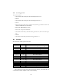
1 General principles
The PCW’s I/O is (for the most part) conducted using the Z80’s IN and OUT instructions, rather than memory-mapped I/O. In nearly all cases, only the bottom 8 bits of the
port number are decoded, and so ports are specified with 2-digit identifiers (eg: port
F0h, not port 00F0h).
2 Boot ROM
Most of this information is derived from Jacob Nevins’ description of the boot process
(with disassembly) at <http://www.chiark.greenend.org.uk/~jacobn/cpm/pcwboot.html>.
The PCW has no separate boot ROM. Instead, on startup, instruction fetches return
a stream of bytes irrespective of address. This stream is 778 bytes long, and generates
a 256-byte boot program at the start of memory (addresses 0002h-0101h). The last
two bytes of the instruction stream (D3 F8) write 0 (’end of boot sequence’) to port
0F8h. The next instruction fetch will then be from address 0002h, the start of the boot
program.
There are two known boot programs; one for dot-matrix PCWs, and one for daisywheel PCWs. They are identical except for two bytes: the code used to check if the boot
sector is valid, and another byte which has presumably been altered so the checksum
comes out the same.
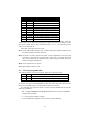
3 RAM and paging
The PCW memory is divided into blocks of 16k. A PCW8256 has 16 blocks, while a
fully-upgraded 2Mb PCW has 128. The processor can only address 64k at a time; the
I/O ports F0h-F3h are used to select which blocks it sees where.
F0h controls what the processor sees at 0000h-3FFFh.
F1h controls what the processor sees at 4000h-7FFFh.
F2h controls what the processor sees at 8000h-BFFFh.
F3h controls what the processor sees at C000h-FFFFh.
3.1 PCW (“extended”) paging mode
Usually, values written to the memory management ports have bit 7 set and the other 7
bits set to the block number:
7
1
6
5
Bits
4 3 2 1
block number
0
- for example, block 4 could be selected into memory at 8000h by an OUT (0F2h),84h.
If the block number is out of range then the top bits will be ignored - so attempting to
select block 24 on a 256k computer would actually select block 8.
5
3.2 CPC (“standard”) paging mode
This paging mode is not used by any CP/M or LocoScript software except perhaps
the memory tester (RAMTEST.COM). It is present because the PCW was based on a
never-built design for ANT1 , a successor to the CPC range.
If CPC paging mode is used, then two blocks can be in one slot at once; memory
writes go to one, and reads to the other.
7
0
6 5
4
block to read
Bits
3
unused
2 1
0
block to write
This method only allows access to the first 128k of memory, which is another good
reason why no PCW programs use it.
There is an additional port used in CPC paging: port F4h (output). The value
written to this is interpreted as follows:
Bits
7
lock C000..FFFF
6
lock 8000..BFFF
5
lock 4000..7FFF
4
lock 0..3FFF
3
2 1 0
unused
If a memory range is set as “locked”, then the “block to read” bits are ignored;
memory is read from the “block to write”.
4 The screen
The screen is a 720x256 array of pixels, each pixel twice as high as it is wide. The
video controller can fetch the screen data from anywhere in the bottom 128k of RAM
- see port F5h below.
4.1 I/O ports
The following ports are used by the video controller:
F5h (output) sets the address of the “Roller-RAM” within the bottom 128k of memory.
The “Roller-RAM” is a 512-byte table whose format is given in section 4.2. The
value written to this port can be interpreted as follows:
7
6 5
block
Bits
4 3 2 1 0
offset / 512
- e.g, to move the Roller-RAM to offset 3200h in memory block 4, write the
value 10011001 binary (99h) to port F5h.
1
Arnold Number Two
6
F6h (output) sets the vertical origin of the screen. The value written to it specifies
which line of the Roller-RAM corresponds to the top line of the screen. So OUT
0F6h, 8 means that the video controller will display pixel line 8 at the top of the
screen - essentially, scrolling up by 8 pixels.
F7h (output) Bits 6 and 7 of this port are used. If bit 7 is set, then the screen will
display in inverse video (black on green/white). If bit 6 is set, then the screen is
displayed; otherwise it will be blank.
F8h (output) This port is used for various purposes, but the two which are videorelated are:
OUT F8h, 8 Disable the video controller. External hardware (a TV modulator?)
must drive the screen.
OUT F8h, 7 Enable the video controller.
F8h (input) The bits that concern the video controller here are:
bit 6 Frame flyback; this is set while the screen is not being drawn.
bit 4 60Hz PCW; only the top 200 lines of the screen will be visible.
4.2 The Roller-RAM
The Roller-RAM is treated as an array of 256 little-endian words. Each word is a coded
pointer to the screen bitmap for this line, formed:
15
14 13
block
12
11
10
Bits
9 8 7
offset / 16
6
5
4
3
2
1 0
offset
The top 3 bits give the memory block number. Bits 0-12 give the offset of the line
within the block. However, it would take 14 bits to span a 16k block, and there are
only 13 left. So to convert bits 0-12 into the address of a screen line, you have to use a
formula such as
address = (offset & 7) + 2 * (offset & 0x1FF8) ;
Once you have the address of a screen line, it consists of 90 bytes, at intervals 8 apart
(so a line would be stored in bytes 0,8,16,24,32...). This allows 8 lines to be interleaved
for ease of printing text.
5 Interrupts
Various peripherals can generate interrupts. When checking the source of an interrupt,
PCW CP/M checks in the order FDC, timer, other peripherals.
7
5.1 Timer interrupts
The timer interrupts 300 times a second. It also increments a counter which can be read
from the bottom 4 bits of port F4h. The counter goes from 0-15, and stays at 15 having
got there. Reading the counter resets it.
This allows PCW system software to compensate for missed timer interrupts. On
interrupt, it reads the counter, and if it is more than 1 then it knows some interrupts
have been missed. If it is 0, then the timer did not interrupt; the interrupt must be from
a different source.
5.2 Floppy controller interrupts
The floppy controller can be programmed to send a normal interrupt or a non-maskable
interrupt (NMI) on completing a command. See Section 8.1.
If the floppy controller has tried to interrupt (regardless of whether it is set to produce an NMI, a normal interrupt, or nothing at all) then bit 5 of the value read from
port F8h will be 1. Otherwise it will be 0.
5.3 Serial port interrupts
The CPS8256 interface (see section 7.1) can be programmed to generate interrupts.
5.4 Daisywheel interrupts
The daisywheel printer (see section 6.2) can be programmed to interrupt when it has
finished a command.
6 Printer ports
6.1 PCW8256/8512/9256/10 printer controller
6.1.1 I/O ports
The PCW uses two I/O ports to communicate with the printer controller - ports 0FCh
and 0FDh. 0FCh appears to be used to initialise the controller, while 0FDh controls the
printer itself.
FCh (input) returns a controller error number. The PCW XBIOS only reads this when
the controller reports an error (see bit 0 of port FDh). Values that can be returned
are:
0 Underrun
1 Printer RAM fault
3 Bad command
5 Print error
0F8h Normal operation (no error).
If this port returns any other value, then “No printer” is displayed as an error.
8
FCh (output) is used to send commands to the printer controller. Each command is a
multiple of 2 bytes long. The meaning of the commands sent to ports FCh and
FDh appears to be the same, but commands are only written to port FCh while
the printer is being reset.
FDh (input) returns the status of the printer. The meanings of the bits are as follows:
Bit
7
6
5
4
3
2
1
0
Meaning
Bail bar - 1 if it’s in, 0 if out
If 0, printer is executing command. If 1, printer has finished.
Always 0 (for daisywheel PCWs, it’s 1 when the PCW is booted,
so this bit can be used to test the printer type).
0 if print head is at left margin; else 1.
Sheet feeder present?
Paper sensor -1 if paper is present, else 0.
If 0, ready - commands can be sent to port FDh. If 1, busy - they can’t.
If 1, controller fault - see IN 0FCh.
FDh (output) is used to send commands to the printer. All printer commands are sent
to this port except during a reset.
6.1.2 Printer commands
Printer commands are a multiple of 2 bytes long. Commands which are longer than
1
in;
two bytes end with the two bytes C0,00. Parameters use a vertical resolution of 360
the horizontal resolution depends on the speed the motor is running at, but is either
1
1
720 in or 1440 in. In the following descriptions, the unit of horizontal measure is called
the “tick”.
00,00 First initialisation command sent to port 0FCh during boot up; possibly does a
self-test.
nn
A4,nn Line feed by 360
inches. Used only for feeds of
followed by a C0,00 command.
1
30 in
and less (ie, n <= 12). Not
A8,nn;A9,nn;AA,nn;AB,nn Move the print head and print a line. Bits 0 and 1 of the
command byte give the print head speed and direction:
bit 0 If set, print head moves to the right; else left.
bit 1 If set, print head moves at half speed. If not, full speed.
The second byte of the command says by how many ticks the head should move
in the direction of travel before the first output is printed. The PCW matrix driver
assumes that the head will actually move by 9 fewer ticks; this may be because
the motor can’t start instantly.
This command is then followed by a number of data commands. These are of
two kinds - to print, or to move the head by a specified number of ticks.
The command to print a column is treated as a 16-bit big-endian word with the
following bitfields:
9
• Bits 15-12 are 0.
• Bits 11-9 give the column spacing. 0 is 5 ticks, 1 is 6 ticks, ..., 7 is 12 ticks.
• Bits 8-0 are 1 to fire the pins. Bit 8 is the bottom pin, bit 0 is the top.
The other type of command moves the head. These are normally at the end (to
put the print head in the right place for the next row). The bit pattern for this type
of command is:
• Bits 15-13 are 1,0,0 (so this command is between 80h and 9Fh).
• Bits 12-0 are the number. If the low 8 bits are 0, add 256. This means
the commands, in increasing numerical order, are: 80,01 80,02 ... 80,FF,
80,00, 81,01 etc.
Finally, the command ends:
C0,00 End of command. This moves the head a further 11 ticks in the direction
of travel, because the motor can’t stop instantly either.
n
AC,nn Line feed by 360
inches. If nn is 0, feed 256
360 inches. To feed more than that,
pass further commands where bits 15-13 are 1,0,0 and bits 12-0 are the encoded
number to feed - eg: AC,30 92,00 C0,00
This command is also terminated by a C0,00 end sequence.
B8,00 Reset printer. Moves the print head to the left margin.
C0,00 end of command sequence.
6.1.3 Example command sequences
• 00,00 A4,01 { A9,C0 } B8,00 - sent to port 0FCh as initialisation sequence. The
A9,C0 pair is sent if the print head is against the left margin after the initial reset;
this ensures that wherever the head was, its ability to move has been tested.
• C0,00 B8,00 - sent to port 0FCh as printer reset sequence.
• AC,3D C0,00 - line feed at 6 lines/inch
• AB,86,0E,data,0E,data,...,0E,data, 02,00, ... (21 times) ..., 80, 04, C0,00 - print
a line of graphics in the ESC L graphics mode. The AB,86 starts printing and
moves the head 134 - 9 = 125 ticks to the right. The commands starting 0E are
the graphics columns, spaced 12 ticks apart. The 21 02,00 commands and the
80,04 move the head 130 ticks to the right of the last column, and the C0,00
moves it a further 11 ticks. Combined with the lead-in on the next line, this
leaves the head ready to print under the first unprinted column of this line.
6.1.4 PCW matrix printer fonts
Although it is not strictly part of the hardware specification, the memory layout used
by the dot-matrix printer fonts under CP/M and LocoScript 1 is described in Appendix
A.
10
6.2 PCW9512 printer controller
Unlike most of the other ports, the 9512 printer controller decodes its I/O address as
more than just 8 bits, and is thus accessed at I/O addresses 00FCh, 01FCh and 00FDh.
The bits returned by IN (0FDh) are:
Bit
7
6
5
4
3
2
1
0
Meaning
1 if the printer can accept commands
0 if commands can’t be sent to it
Usually 0. The interrupt handler checks this bit,.
but the significance of it is unclear.
1 if the printer is idle, 0 if it’s executing a command.
On dot-matrix PCWs, this bit is always 0.
Always seems to be 1
Unknown
1 if the printer has caused an interrupt.
0 if bytes can be sent to the controller, else 1.
1 if bytes can be read from the controller, else 0.
The controller is accessed by sending two-byte commands. The first byte specifies
the command, and the second contains any required data. To send a command:
1. Wait until IN (00FDh) bit 1 is zero.
2. OUT (01FCh),command_byte
3. OUT (00FCh),data_byte
If the command returns data, then to read back the data, do:
1. Wait until IN (00FDh) bit 0 is 1.
2. Read data from IN (00FCh).
To read the status of the printer, do an IN (01FCh) twice in succession. If the values
read don’t match, repeat until they do. The bits in the byte returned are:
Bit
7
6
5
4
3
2
1
0
Meaning if set
Printer failed
No printer
Ribbon present
Paper present
Cover down
Bail bar in
Controller failed
?
(The PCW9512 schematic shows printer signals for “SEL.HOM”, “CAR.HOM”,
“SHIF” and “PSIF”, but whether any of these corresponds to bit 0 (or indeed bits 7, 6
and 1) of this port is not known).
11
Daisywheel commands should be treated as big-endian words. The first 4 bits
define the command; the remaining 12 bits are the parameter. If the first 4 bits are
0, then the next 4 bits define a different type of command and the last 8 bits are the
parameter.
First byte
High 4 bits Low 4 bits
0
1
0
0
0
0
0
0
0
0
2
3
4
5
6
7
8
9
0
0
1
0Ah
0Bh
2
2
3
4
5
6
7
8
9
A
B
C
D
E
F
Second byte
Effect
ribbon type
3 for singlestrike, else 0Ch
0
1 or 3
value
0
0
80h
07Fh
0
Prepare to output character
Followed by 4xxx-7xxx
Get PAR port status
Unknown
Write byte to PAR port
Used to re-check paper sensor?
Used to re-check paper sensor?
Enable daisywheel interrupts
Disable daisywheel interrupts
Reset interrupt flag
(called from interrupt handler)
22h, 24h, 25h
Unknown
3
Unknown
0
Initialise controller. This is
the first command sent.
The PCW9512 BIOS does not
send these codes.
Bits 12-9 are impression
Output specified character.
(2 for low, 5 for medium, 9 for high)
Always preceded by a
Bits 0-7 are pin number on wheel.
01xx command.
Not sent by the PCW9512 BIOS
1
ths of an inch
Distance in 120
Move left
unknown
Unknown
1
ths of an inch
Distance in 120
Move right
1
ths of an inch
Distance in 192
Feed paper forwards
0
Unknown
1
ths of an inch
Distance in 192
Feed paper backwards
0
Unknown
6.3 PCW9512 PAR port
The PAR port is part of the PCW9512 printer controller, and is controlled by commands
2 (get status) and 4 (write byte to PAR).
The status byte gives the values of the following Centronics lines:
12
Returns
nothing
status
nothing
nothing
nothing
byte
nothing
nothing
nothing
byte
byte
0 if OK
else error
nothing
nothing
nothing
nothing
nothing
nothing
nothing
nothing
Bit
7
6
5
4
3
2
1
0
Line
ACK
BUSY
ERROR
SELECT
PAPER OUT
Always 0?
Always 0?
Always 1?
So to do output, wait until bit 6 goes to 0 and then write the data using command 4.
Since the 9512 hardware supports the Centronics ACK signal, it is possible for a
9512 to act as the master computer in a LocoLink conversation - see section 7.3.
6.4 CPS8256 CEN port
The CPS8256 CEN port is at E3h.
To read its status, write 10h to port E3h. Then read port E3h; bit 5 is set if the
printer is ready.
To write data, write the character to port E8h. Then send the following bytes to port
E3h: 5, E8h, 5, 68h. These will toggle the STROBE line.
6.5 Standalone CEN port
The standalone CEN port is at ports 84h-87h.
The status is read from IN (84h). Bit 0 is1 if the printer is busy, 0 if it’s ready.
To write a byte, write it to port 87h, then to port 85h, then to port 87h again. The
two writes to port 87h toggle the STROBE line.
7 Communications interfaces
7.1 CPS8256
The CPS8256 is based on a Z80-DART and an 8253 timer. Ports are as follows:
Port
E0
E1
E2
E3
E4
E5
E7
Meaning
DART Channel A data
DART Channel A control
DART Channel B data
DART Channel B control
8253 counter 0
8253 counter 1
8253 write mode word
To write a value to a DART register other than register 0, send the register number
and then the value to the “control” port (E1h or E3h). To read a register, send the
register number to the control port and then do an IN on that port.
13
To read / write DART register 0, just read or write the value to port E1h or E3h.
When writing, the bottom 3 bits of the value must be 0; otherwise one of the other
regsters would be selected.
7.1.1 Z80-DART registers
The Z80-DART registers are numbered 0 to 5. Many of the bits in these registers are
not used by the CPS8256.
Register
0
1
2
3
4
5
A Only
B Only
Bit
0
1
2
3
4
5
6
7
0
1
2
3
4
5
6
7
Meaning when read
Receive character available
Interrupt pendingA
Transmit buffer empty
DCD
Ring Indicator
CTS
Not used
Break
All sent
Not used
Not used
Not used
Parity error
Receive overrun
Framing error
Not used
Interrupt vectorB
0
1-4
5
6-7
0
1
2-3
4-5
6-7
0
1
2
3
4
5-6
7
on channel A
on channel B
14
Meaning when written
Must be 0
Must be 0
Must be 0
Command
Command
Command
Not used
Not used
Ext int enable
Transmit int enable
Status affects vectorB
Receive int mode
Receive int mode
Wait/Ready on R/T
Wait/Ready function
Wait/Ready enable
Interrupt vectorB
Receive enable
Must be set to 0
RTS/CTS set automatically
Receive bits (5,6,7,8)
Parity enabled
Parity even
Stop bits (1, 2, 3 for 1, 1.5, 2)
Not used
Clock multiplier(1,16,32,64)
Not used
RTS
Not used
Transmit enable
Send break
Transmit bits (5,6,7,8)
Not used
7.1.2 CPS8256 Centronics port
The Centronics port (described in section 6.4) returns its status in register 0 of Channel
B. The STROBE signal is controlled by bit 7 of register 5 (what the DART thinks is
DTR) and the BUSY signal shows up in bit 5 (CTS) of register 0.
7.1.3 CPS8256 Serial port
The serial port is connected to Channel A of the DART.
• To check if the port can output, read register 0 of Channel A.
• If you are using software handshaking, check bit 2 (Transmit buffer empty) and
wait until it’s nonzero.
• If you are using hardware handshaking, check bit 5 (Clear to Send); when this
goes to 1, read register 1 until bit 0 (All Sent) is 1.
• Then, to output, write the correct byte to the data channel.
To read from the port in non-interrupt mode:
• If hardware handshaking is enabled, check bit 0 of register 0 (RX character available) and if it’s 0, raise DTR (set bit 7 of register 5).
• Wait until bit 0 of register 0 becomes 1.
• Read the character from the DART data channel.
• If hardware handshaking is in use, drop DTR.
To set transmit baud rate, send 36h to port E7h, and two bytes encoded rate to port E4h.
To set the receive baud rate, send 76h to port E7h, and the two bytes to port E5h.
The encoded rate is 125000
baud - send the high byte first, then the low byte.
7.2 SCA Mark 2 Interface
The SCA interface is programmed in the same way as the CPS8256, except that there’s
also a Real Time Clock fitted. The RTC is not emulated in JOYCE so this information
has not been verified; use it at your own risk.
To read a byte from the RTC:
• Set channel A DTR.
• Reset channel B.
• For each bit: Unset channel A DTR, read the channel B Ring Indicator, and set
channel A DTR. The bit obtained should be complemented. The first bit read is
bit 7 of the byte; the last is bit 0.
To write a byte to the RTC:
• Set channel A DTR.
• For each bit, if it’s a 1 then reset channel B. If it’s a zero set channel B RTS.
Then reset and set channel A DTR.
15
• Finally, unset channel A DTR, reset channel B, read a single bit from the channel
B Ring Indicator, and set channel A DTR again.
To send an RTC command:
• To start the command: Unset channel A DTR, reset channel B, set channel B
RTS then set channel A DTR.
• Send the command bytes using the write code above.
• Read any result bytes using the read code above. For all result bytes except the
last: Reset channel B, set channel B RTS, unset channel A DTR, set channel A
DTR and then reset channel B again.
• Finally, set channel B RTS, set channel A DTR, unset channel A DTR and then
reset channel B.
To read the clock:
• Send the command D0h, 0.
• Send the command D1h; the next 4 bytes read will be hours, minutes, days,
months (BCD).
• Send the command D0h, 5.
• The clock will return 3 bytes. The first is the year (BCD); I suspect the others
are day and month again, which we ignore.
To write to the clock:
• Send the command D0h, 20h.
• Send the command D0h, hours, minutes, days, months (all BCD).
or:
• Send the command D0h, 5.
• Send the command D0h, year, day, month (BCD).
7.3 LocoLink interface
LocoLink is used to connect the PCW to the parallel port of another computer. The
supplied software acts as a file server (“slave” in LocoLink terminology), so that the
other computer (the “master” - normally a PC, though software also existed allowing
a PCW9512 to do it, and the PCW16 is supposed to have built-in LocoLink support)
could read or write files.
Although the LocoLink interface connects to the parallel port, it acts as a serial device, using only 4 wires (two each way). This is so that it can support non-bidirectional
parallel ports.
On a PCW with the interface, the LocoLink appears at address 0FEh. The port
behaves as follows:
16
Bit
0
1
Input meaning
Data 0
Data 1
Output meaning
BUSY
ACK
At the other end of the parallel cable, the two “Data” lines correspond to the first
two data lines in the parallel port. BUSY and ACK correspond to the Centronics pins
of the same name.
If a LocoLink interface is connected to both the expansion and parallel ports of
a PCW9512, and bytes are sent to port 0FEh, the bits in the parallel port change as
follows:
Value written
Bit 1 Bit 0
0
0
0
1
1
0
1
1
Value read
Bit 7 Bit 6
1
1
1
0
0
1
0
0
JOYCE v2.1.0+ contains support for the “slave” end of a LocoLink connection.
The communications protocol used by the LocoLink interface is described in Appendix B.
7.4 PCW Linkit
The PCW Linkit interface is a similar device to the LocoLink (a 2-bit communication
channel) except that both ends connect to PCW expansion ports. It appears at port
0FFh. The values are carried by the two low bits of the port; the value read by one
PCW is the binary inverse of the value written by the other PCW.
The communications protocol used is not known.
7.5 Prototype serial interface
The original PCW specification mentions that the prototype PCW had a serial interface
based on the Intersil IM6403 UART. Its data register was at address 0FEh for both input
and output, and its status register at 0F9h (input only). JOYCE does not emulate this
interface.
8 Floppy drives
The PCW floppy controller is the uPD765A, run in non-DMA mode. The FDC main
status register is at I/O port 00h; its data register is at 01h.
8.1 The floppy controller and other ports
The System Control port (0F8h) has five commands which affect the floppy controller:
02 If the floppy controller interrupts, the Z80 gets an NMI.
03 If the floppy controller interrupts, the Z80 gets a normal interrupt. If the Z80 has
disabled interrupts, the interrupt line stays high until the Z80 enables them again.
17
04 Floppy controller interrupts are ignored.
05 Set the floppy controller’s “Terminal count”, which aborts a data transfer.
06 Clear the floppy controller’s terminal count.
8.2 Floppy drive support
PCW operating systems support two floppy drives, connected to the controller as drives
0 and 1.
On a PCW 8256, 8512 or 9512, commands for drives 2 and 3 are sent to drives 0
and 1 (ie, the drive number is not completely decoded).
On a PCW 9256, 9512+ or 10, commands for drive 2 appear to go to drive 1, except
that the drive is always “ready”, even when the motor isn’t running. As far as I can see
from the schematic, selecting drive 3 selects both drives simultaneously.
8.3 Floppy controller probe
Versions of LocoScript and CP/M written after the PCW9256 was released contain
code to discover what sort of PCW is in use - 8256/8512/9512 or 9256/9512+/10. The
code then detects whether 3.5” disc drives are in use.
The test is done in two stages.
8.3.1 Detect floppy controller type
1. Stop disc motors.
2. Send SENSE DRIVE STATUS for drive 0 to the disc controller until it reports
drive 0 is not ready.
3. Send SENSE DRIVE STATUS for drive 2. On an 8256, 8512 or 9512, this
returns the same status as drive 0 (ie: not ready). But on a 9256, 9512+ or 10, it
returns a status of “ready”.
8.3.2 Detect drive type
If a 9256-style controller was found, separate checks are then done on each drive to see
whether they are 3.5” or not. The test is performed once on drive 0 and once on drive 2.
The test on drive 2 will return results that are valid for drive 1, for some strange reason.
1. Start disc motors.
2. Recalibrate the drive (ie, move the head to track 0).
3. Send SENSE DRIVE STATUS to the drive.
4. If the “Track 0” bit is not set:
• For drive 0: If the “read-only” bit is set, the drive is 3”. Otherwise it is
3.5”.
• For drive 2: The drive does not exist.
5. If the “Track 0” bit is set:
18
• Turn off the disc motors, and wait for them to stop.
• Send SENSE DRIVE STATUS to the drive again. If “Track 0” is set, the
drive is 3”. Otherwise it is 3.5”.
9 Hard drives
JOYCE does not emulate real PCW hard drives, so this information is not verified.
9.1 Cirtech Gem
Physically, the Gem drive (at least the one I have) is a Seagate ST351A/X IDE drive,
jumpered for XT mode. If the jumpers are set for AT mode it is possible to connect it
to a modern PC and access the data at a sector level. Jumper settings for the ST351A/X
can be found on Dell’s website: <http://support.euro.dell.com/support/edocs/dta/18814/00000003.htm>.
In XTA mode the drive has four registers, mimicking an XT hard drive controller.
On the PCW they can be found at ports 0A8h to 0ABh. The information below is
adapted from the Interrupt List entry for ports 0320h-0323h, which is where the registers appear on a PC. For full programming information, see the IBM PC technical
reference, pages 1-187 to 1-201.
0A8h Data register.
0A9h When read: controller status. When written: Reset controller.
0AAh When read: controller DIP switches. When written: Generate controller-select
pulse.
0ABh When written: DMA and interrupt mask (not used on the PCW)
In addition, the Gem interface has a 4k boot ROM. It would appear that on initial
startup, memory accesses with A7 reset go to the boot ROM, while memory accesses
with A7 set go to the PCW mainboard. So the 4k ROM is mapped into memory from
0000-007F, 0100-017F, 0200-027F, ..., 1F00-1F7F.
The first thing the GEM boot rom does is to mimic the normal PCW boot process
by copying the standard boot image (section 2) into memory. It does this by repeated
memory reads (from address 80h, so with A7 set) until the sequence D3 F8 [OUT
(0F8h),A] is encountered. Then it executes its own write to that port to switch to
normal execution, and copies itself into RAM.
While the ROM is paged in, all I/O port accesses use 16-bit I/O [OUT (C),A style],
with the top 8 bits of the address set to 80h. The first instruction after the boot ROM
has been copied into RAM is IN A,(0A9h), with A=0. Presumably this I/O read, with
the top 8 bits of the address all 0, pages the boot ROM out.
The format of the Gem drive boot track is documented in Appendix C.
In a Gem-2 (mirrored) configuration, the ’main’ drive is drive 1 (ie, jumpered as
slave) and the ’backup’ drive is drive 0 (ie, jumpered as master).
9.1.1 Cirtech Gem (ATA)
I’ve also seen (but not really studied) a Gem drive based on a Conner Peripherals
CP3024, which is ATA rather than XTA. The ATA registers would be mapped at 0A8h0AFh:
19
0A8h Data
0A9h Error / Features
0AAh Sector count
0ABh Sector number
0ACh Cylinder low
0ADh Cylinder high
0AEh Drive / Head
0AFh Status / Command
with the interface presumably converting between the 16-bit transfers expected by the
drive, and the 8-bit transfers done by the Z80.
9.1.2 Cirtech Insyder / Hardpak
These are pretty much Gem drives in different form factors (the Insyder is fitted inside a PCW9512, and the Hardpak includes a 2.5” hard drive in the interface box).
Presumably they would use the same register interface as the Gem.
9.2 ASD PCWHD10 / PCWHD20
I haven’t seen one of these drives, so this information comes from disassembling the
driver (ASD.FID). The drive uses an ATA interface, and appears to make 8-bit transfers.
The registers are:
0A0h Data
0A1h Error / Features
0A2h Sector count
0A3h Sector number
0A4h Cylinder low
0A5h Cylinder high
0A6h Drive / Head
0A7h Status / Command
The review in ’8000 Plus’ says that the ASD drive can have 1-6 partitions, but the
driver I have doesn’t support this.
20
9.3 Other hard drives
’8000 Plus’ has also reviewed several other hard drives, for which I have no programming information:
Timatic Winchester Expansion Box: A Seagate ST225, connected through a SASI
interface.
ACC Hard Disc: No information available.
Vortex System 2000: A Miniscribe 8450 XT, connected through a SCSI interface.
Cirtech Diamond: An earlier version of the Gem, but based on a SCSI interface rather
than IDE. Among its features was the ability to connect up to seven PCWs to a
single drive, taking advantage of the ability of the SCSI bus to support multiple
controllers.
Cirtech Flash Drive: A solid-state boot device which connects to the expansion port,
and boots the PCW from a Flash ROM.
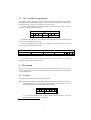
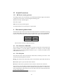
10 Keyboard
The keyboard appears as a memory-mapped device at 3FF0h-3FFFh in memory block
3. The first 12 bytes give the status of pressed keys:
Address
Bit 7
Bit 6
Bit 5
Bit 4
Bit 3
Bit 2
3FF0h
Keypad 2 Keypad 3
Keypad 6
Keypad 9
Paste
F1/F2
3FF1h
Keypad 1 Keypad 5
Keypad 4
Keypad 8
Copy
Cut
1/2
3FF2h
[+]
Shift (both)
Keypad 7
>
Return
3FF3h
.
?
;
<
P
[
3FF4h
,
M
K
L
I
O
3FF5h
Space
N
J
H
Y
U
3FF6h
V
B
F
G
T
R
3FF7h
X
C
D
S
W
E
3FF8h
Z
Shift Lock
A
Tab
Q
Stop
3FF9h
<-Del
J1: Fire 1
J1: Fire 2 J1: Right J1: Left
3FFAh
Alt
Keypad .
Keypad Enter
F7/F8
[-]
Cancel
3FFBh
J2: Fire 1
J2: Fire 2 J2: Right J2: Left
Using the key numbering scheme in the PCW manual:
• Keys 0-71 correspond to bit (n mod 8) of byte (n / 8) of the map.
• Key 72 corresponds to bit 7 of byte 9.
• Keys 73-80 correspond to bits 0-7 of byte 10.
The entries marked J1 and J2 are for keyboard joysticks (see below).
The last four bytes contain controller status in bits 6 and 7. Bits 0-5 of each byte
are used (by analogy with the two joystick entries) to provide keyboard combinations
that may be useful as joysticks.
21
Bit 1
Keypad 0
PTR
]
9
7
S
3
2
J1:Down
Extra
J2: Down
Bit 0
F3/F4
Exit
Del->
=
0
8
6
4
1
J1:Up
F5/F6
J2: Up
Address
Bit 7
Bit 6
3FFCh
(with LK2 present)
3FFDh
~LK2 Shift Lock
LED
3FFEh
LK3
LK1
3FFFh
Update
flag
Ticker
Bit 5
(KP Enter)
(Shift)
(Space)
Bit 4
(Space)
(S)
(KP 2)
Bit 3
(KP 0)
(D)
(KP 3)
Bit 2
(Exit)
(A)
(KP 1)
Bit 1
(F1/F2)
(X)
(KP .)
Bit 0
(F3/F4)
(W)
(KP 5)
(Shift)
(Space)
(Shift)
(Space)
WRP]
; > . 1/2
WRP[
SFXV
QEO[
L<,/
QEO[
ADZC
ZXCV
BNM
BNM
, . /1/2
ASDF
GHJ
HJKL
;<>
3FFCh gives an inverted T pattern centred on F1. If link LK2 is present, it will also
respond to a W/A/D/X diamond, with S as Fire 1 and Shift as Fire 2.
3FFDh maps to the numeric keypad.
3FFDh bit 6 reports the state of the Shift Lock LED; 1 if lit, else 0.
3FFDh bit 7 is 0 if LK2 is present, 1 if not.
3FFEh maps ASDFGHJ to up, ZXCVBNM to down, QEO[L</, to left, WRP];>.1/2
to right, Space to Fire 1, Shift to Fire 2.
3FFEh bit 6 is 1 if LK1 is present, 0 if not. However, if LK1 is present the keyboard
enters a self-test mode and transmits test patterns rather than these flags.
3FFEh bit 7 is 1 if LK3 is present, 0 if not.
3FFFh maps HJKL;<> to up, BNM,./1/2 to down, QEO[ADZC to left, WRP[SFXV to
right, Space to Fire 1, Shift to Fire 2.
3FFFh bit 6 toggles with each update from the keyboard to the PCW.
3FFFh bit 7 is 1 if the keyboard is currently transmitting its state to the PCW, 0 if it
is scanning its keys.
If no keyboard is present, all 16 bytes of the memory map are zero.
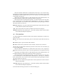
10.1 Keyboard matrix
The physical layout of the keyboard matrix is given in the service manual:
Pin
DB7
DB6
DB5
DB4
DB3
P10 Keypad 2 Keypad 3
Keypad 6
Keypad 9
Paste
P11 Keypad 1 Keypad 5
Keypad 4
Keypad 8
Copy
1/2
P12
[+]
Shift (both)
Keypad 7
>
P13
.
?
;
<
P
P14
,
M
K
L
I
P15
Space
N
J
H
Y
P16
V
B
F
G
T
P17
X
C
D
S
W
P24
Z
Shift Lock
A
Tab
Q
P25
<-Del
Keypad .
Keypad Enter
F7/F8
[-]
P26
Alt
J1: Fire 1
J1: Fire 2 J1: Right
P27
J2: Fire 1
J2: Fire 2 J2: Right
22
DB2
F1/F2
Cut
Return
[
O
U
R
E
Stop
Cancel
J1: Left
J2: Left
DB1
Keypad 0
PTR
]
9
7
S
3
2
Extra
J1: Down
J2: Down
DB0
F3/F4
Exit
Del->
=
0
8
6
4
1
F5/F6
J1: Up
J2: Up
10.2 Keyboard Links
The keyboard has three option links. By default they are all disconnected.
LK1: If connected, puts the keyboard into a test mode in which it repeatedly sends
various patterns of data to the PCW. The Shift Lock LED will be constantly lit
(or, more accurately, blinking faster than you can see).
LK2: If connected, pressing Shift does not cancel Shift Lock. Also enables W/A/D/X
joystick, and resets bit 7 of byte 3FFDh.
LK3: If connected, sets bit 7 of byte 3FFEh. Has no other effects.
10.3 Keyboard Joystick(s)
The key numbering scheme on the PCW exactly matches the memory map until the
gap at key 72. It also exactly matches the keyboard matrix schematic in the PCW9512
service manual - until key 72.
As shown above, the keyboard schematic has entries in its matrix table for one
or two joysticks. (Existing PCWs have no provision for connecting a joystick to the
keyboard, but the PC1512 does). This may have been how the joystick(s) on ANT were
to have been implemented.
My guess is that in the original ANT design, the keyboard matrix and the table
in memory matched. When the PCW keyboard was created, the membrane was redesigned to move the now-redundant joysticks to the end of the layout, and the keyboard controller microcode rewritten to swap bytes 9 and 10 (bits 0-6) so their positions
in the memory map didn’t change.
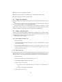
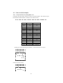
10.4 Physical connection
+5v
GND
Data Clock
The pinout above shows the keyboard socket on the PCW, seen from the outside of
the case. The voltages used for signalling appear to be less than TTL normal, though
the PCW9512 (and probably the other models) can take signals at TTL levels without
apparent harm.
23
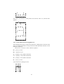
10.4.1 Wire protocol
By default, the data and clock lines are high. To send a bit, the keyboard drives the
data line low or high, pulls the clock line low, and then a little later returns them both
to high. Exact timings are unknown, though the PCW motherboard seems happy to
accept timings similar to those used by the PC1512 keyboard (set data, wait for 5µs,
set clock, wait for 5µs, return both lines to high, wait for 40µs).
A keycode is 12 bits long, with the most significant bit first. The first four bits are
the offset in the memory map (0-0Fh), and the last eight bits are the value to be placed
into memory at that address. The PCW keyboard toggles the DATA line twice before
sending each word, but the gate array at the PCW end doesn’t seem to need this.
When transmitting its state, the controller sends a 17-keycode packet. The first
word is byte 0Fh, with the top bit set to 1; then bytes 0-0Eh; then byte 0Fh again, with
the top bit set to 0.
11 Pointing Devices
11.1 AMX Mouse
This mouse appears at ports 0A0h-0A3h. The interface is built around an 8255 PPI:
0A0h (port A) gives vertical movement - low nibble = number of moves up, high =
number of moves down
0A1h (port B) gives horizontal movement - low nibble = number of moves right, high
= number of moves left
0A2h (port C)
Input: gives button state in bottom 3 bits. These are 0 if the button is pressed,
else 1. Bit 0 is the left button; Bit 1 is middle; Bit 2 is right.
Output: Stop Press writes 0FFh followed by 0, presumably to reset the counters.
0A3h (PPI mode). Stop Press writes 93h at startup (Basic I/O mode, ports A and B
input, port C low 4 bits input, high 4 bits output).
If at startup the value read from port 0A2h is 10h, Stop Press switches to accessing the
AMX mouse through ports 80h-83h. Possibly this is to detect an ASD hard drive and
avoid a conflict.
11.2 Kempston Mouse
This mouse appears at ports 0D0h-0D4h:
0D0h gives X position, 0-255. The same value can also be read from 0D2h.
0D1h gives Y position, 0-255. The same value can also be read from 0D3h.
0D4h gives button state in bottom 2 bits. Zero if the button is pressed, else 1. Bit 0 is
left; bit 1 is right. Other bits are 1.
24
11.3 Keymouse
The Keymouse connects between the PCW and the keyboard. It uses the same mechanism as the keyboard to appear as a memory-mapped device, replacing four of the
keyboard joystick bytes:
3FFBh Bits 6-0: horizontal movement counter. Bit 7: Middle mouse button pressed.
3FFCh Bits 7-6: high bits of vertical movement counter.
3FFDh Bits 4-0: low bits of vertical movement counter.
3FFEh Bit 7: Left button. Bit 6: Right button.
11.4 Electric Studio light pen
The lightpen appears at ports 0A6h and 0A7h. The method it uses to encode its position
is not known.
12 Joysticks
12.1 Keyboard joystick(s)
These are described in section 10.3.
12.2 Kempston interface
The Kempston interface is visible at port 9Fh. It appears to have the same bit assignments as the Spectrum version of the interface:
Bits 7-5 Ignored.
Bit 4 1 if the fire button is pressed.
Bit 3 1 if the joystick is pushed down.
Bit 2 1 if the joystick is pushed up.
Bit 1 1 if the joystick is pushed left.
Bit 0 1 if the joystick is pushed right.
12.3 Spectravideo interface
The Spectravideo joystick interface appears at 0E0h (so it cannot be used at the same
time as a CPS8256 interface). The values it returns are:
Bit 7 Always 0. If nothing is present on this port, 1 is returned.
Bit 6 Ignored.
Bit 5 Ignored.
Bit 4 1 if the joystick is pushed to the right.
25
Bit 3 1 if the joystick is pushed up.
Bit 2 1 if the joystick is pushed to the left.
Bit 1 1 if the fire button is depressed.
Bit 0 1 if the joystick is pushed down.
12.4 Cascade interface
The Cascade joystick interface also appears at 0E0h. The ’Head over Heels’ driver for
this joystick doesn’t work with a Spectravideo interface; it uses these bits:
Bit 7 0 if the fire button is pressed.
Bit 6 Ignored.
Bit 5 Ignored.
Bit 4 0 if the joystick is pushed up.
Bit 3 Ignored.
Bit 2 0 if the joystick is pushed down.
Bit 1 0 if the joystick is pushed to the right.
Bit 0 0 if the joystick is pushed to the left.
12.5 DKTronics interface
The DKTronics interface appears to be one register on a larger chip. To read it, write
0Eh to port 0AAh and then read port A9h. The use of register 0Eh and the presence
of a “DKTronics sound” driver in Head Over Heels suggests that the chip may be an
AY-3-8912 or similar sound generator.
Head Over Heels uses these bits of the value that it reads:
Bit 7 Ignored.
Bit 6 0 if the fire button is pressed.
Bit 5 0 if the joystick is pushed up.
Bit 4 0 if the joystick is pushed down.
Bit 3 0 if the joystick is pushed to the right.
Bit 2 0 if the joystick is pushed to the left.
Bit 1 Ignored.
Bit 0 Ignored.
26
13 Sound Generators
13.1 DKTronics sound generator
According to posts on www.amstrad.es, if I read Google Translate aright, this interface
is based on an AY-3-8912, accessed using the following ports:
A9 Read currently selected register
AA Select register
AB Write currently selected register
As mentioned above, the joystick port is register 0Eh.
A
Dot matrix printer fonts
The PCW dot-matrix fonts are stored in three tables in Bank 2. The addresses and sizes
of these tables differ from CP/M version to CP/M version; you can use LPT8FONT2
to discover where the fonts are for a given CP/M version. Known font addresses are:
CP/M version
1.1, 1.2,1.4
1.12,1.14,1.15
Font starts at
5E28h
5EBDh
There are three consecutive tables of font data:
A.1 The character width table.
This is always 64 bytes long, and used for spacing the characters when proportional
mode is selected. To get the width for character <n>, read byte (<n>/2); the high
nibble will be for the even-numbered character (0,2,4,...) and the low nibble for the
odd-numbered one (1,3,5,...)
A.2 The NLQ font
The font starts with a table (the character offset table) containing 129 words. Each
word has the following bitwise structure:
Bit 15: The character has a descender; print it on the bottom 8 pins rather than the top
8.
Bits 14-12: Space to put at the left of this character.
Bits 11-0: Offset of the specification of this character, from the start of the font.
The last entry gives the offset of the first byte after the font. This means that for any
character, the size of its description can be found by taking offset(char+1) - offset(char).
In the standard fonts, offset(128) also gives the offset of the start of the draft font from
the start of the NLQ font.
2 <http://www.seasip.demon.co.uk/Cpm/software/amstrad.html>
27
After the character offset table is a pattern table. Each entry in it is two bytes long;
the high byte is printed on the first pass, and the low byte on the second (or vice versa?
The high byte is drawn slightly above the low one, anyway). The least significant bit
corresponds to the top pin.
The length of the pattern table isn’t that important, but in the standard fonts it can
be deduced simply by subtracting 258 from the offset of character 0.
After that we have the character descriptions. As mentioned above, for each character, its description is from offset(char) to offset(char+1). An entry is a stream of
bytes. If the top bit is set, it means: Leave a blank column before printing this column.
The values of the low 7 bits are:
00h-79h: Multiply by 2 to get an offset into the pattern table. Then take the two bytes
at that offset for the first and second pass.
7Ah: The two bytes after this code are printed on the first and second pass.
7Bh-7Fh: Repeat the next pattern (byte - 79h) times, putting a blank column before
the second and subsequent repetitions.
A.3 The draft font
As with the NLQ font, the draft font starts with a character offset table, in which every
word is formed:
Bit 15: The character has a descender; print it on the bottom 8 pins rather than the top
8.
Bits 14-12: Space to put at the left of this character.
Bits 11-0: Offset of the specification of this character, from the start of the font.
The last entry gives the offset of the first byte after the font. Fonts can use memory up
to and including 6BFFh.
After the character offset table is a pattern table. Each entry in it is a single byte,
since draft mode only prints one pass. The least significant bit corresponds to the top
pin.
The length of the pattern table isn’t that important, but in the standard fonts it can
be deduced simply by subtracting 258 from the offset of character 0.
After that we have the character descriptions. As mentioned above, for each character, its description is from offset(char) to offset(char+1). An entry is a stream of
bytes. If the top bit is set, it means: Leave a blank column before printing this column.
The values of the low 7 bits are:
00h-79h: This is an offset into the pattern table. The bit pattern for the next column is
the byte at that offset.
7Ah-7Fh: Repeat the next pattern (byte - 78h) times, putting a blank column before
the second and subsequent repetitions.
(note that unlike the NLQ print, there is no literal bitmap type).
28
A.4 Some worked examples
A.4.1 NLQ: Character 0 (à) using BIOS 1.15
Looking in the NLQ table, the first 2 entries are 01F6h 0209h. The character bytes
between those offsets (60F3h - 6106h) are (all values in hex):
2E 14 15 03 08 1A 08 7A 01 44 08 4C 08 36 20 0A 2B 02 82
Byte(s)
2E
14
15
03
08
1A
08
7A 01 44
08
4C
08
36
20
0A
2B
02
82
First pattern
30
04
00
00
08
00
08
01
08
00
08
20
08
04
38
00
(gap) 00
Second pattern
20
40
10
44
00
45
00
44
00
46
00
04
40
00
38
40
(gap) 40
Which gives us the following two patterns - one from the first set of bytes:
3000000000020030 0
0400808180808480 0
.......#..........
.
.
.#
# .
. # # # # # # .
#
# .
#
# # .
.
.
..................
and one from the second:
2414040404004034 4
0004050406040080 0
.....#............
.
#
.
. # # # # #
.
.
# .
29
. #
# .
#
# .
.# # # # # # # #
..................
If we take a row from the second pattern, then the first, and so on, then the letter
appears:
.....2............
.
1
.
.
2
.
.
.
. 2 2 2 2 2
.
.1
1 .
.
2 .
. 1 1 1 1 1 1 .
. 2
2 .
1
1 .
2
2 .
1
1 1 .
.2 2 2 2 2 2 2 2
.
.
.
.
..................
A.4.2 Draft: Character 0 (à) using BIOS 1.15
In the draft table, the first two words are 0157h 015Ch. Adding these to the base of the
font gives 6948h and 694Dh; so the bytes between 6948h and 694Ch inclusive are the
pattern for character 0.
The bytes are: 05 0E 97 C7 92 01 and these expand to:
05 -> patt[ 5] = 0x20
0E -> patt[14] = 0x54
97 -> patt[23] = 0x55, blank column first
C7 -> patt[71] = 0x56, blank column first
92 -> patt[18] = 0x38, blank column first
01 -> patt[ 1] = 0x40
and, translated to a bitmap, these are:
25 5 5 34
04 5 6 80
...#.....
.
# .
.# # # .
.
#.
.# # # #.
30
#
#.
.# # # #
.........
A.4.3 Repetition of columns: Character 62 (’=’) using BIOS 1.4
This character is number 62. So 124 bytes from the start of the offset table, we find the
two words 02B3h, 02B5h. Thus we know the character description fits in 2 bytes, and
starts 02B3h bytes from the start of the font.
The two bytes found there are:
7Dh [repeat 5 times]
0Ah [pattern]
Entry 0Ah in the pattern table is 14h, so the character is formed:
.........
.
.
# # # # #
.
.
# # # # #
.
.
.
.
.........
with the blank columns inserted automatically.
A.5 Matrix fonts in LocoScript 1.20
The fonts are stored in the file MATRIX.STD on the boot disc, in the same order as in
CP/M. The data start at an offset of 011Ah from the start of the file.
LocoScript 1 is able to print 224 characters - numbers 0-127 and 160-255. These
are stored as a single block of bitmaps in MATRIX.STD, which subtracts 32 from
character codes above 160 to create its internal character index.
The design of MATRIX.STD as a separate file seems to imply that other dot-matrix
fonts could be loaded in LocoScript 1. However the only alternative LS1 fonts I’ve seen
(in Digita International’s Supertype) simply patch the existing MATRIX.STD file.
Note that later versions of LocoScript 1 (v1.30+) use the same font format, but
different file formats - see below.
A.5.1 PS widths table
There are 224 characters rather than 128, so the PS widths table is 112 bytes long.
A.5.2 NLQ font
Since there are 224 characters, the offsets table is 225 words long. The offsets to
characters start at 0; ie, what must be added is the address of the character description
table, not the address of the font itself. The offset table is at 18Ah in the file, and the
character description table is at 442h. The character description bytes are almost the
same as in CP/M, but the special values of the low 7 bits are slightly different:
31
00h-7Ah: Multiply by 2 to get an offset into the pattern table. Then take the two bytes
at that offset for the first and second pass.
7Bh: The two bytes after this code are printed on the first and second pass.
7Ch-7Fh: Repeat the next pattern (byte - 79h) times, putting a blank column before
the second and subsequent repetitions.
A.5.3 Draft font
The draft font is at offset 1181h in MATRIX.STD. Its offsets table is again 225 words
long; offsets are based on the font address, like in CP/M.
A.5.4 Z80 code
The first 11Ah bytes of MATRIX.STD are the Z80 code that generates font bitmaps.
Again, this seems to suggest that alternative fonts were planned; the people designing
the characters would have been able to use any code they liked to generate them. Very
similar code is used under CP/M.
The entry point is at the beginning of MATRIX.STD, and takes the following parameters:
A = harater
BC = address of this routine (MATRIX.STD must be prepared to be loaded anywhere in mem
DE = address of a byte to whih harater width should be written.
On return, the registers should be:
A = harater
BC = address of the ode that generates the harater bitmaps
PS width of harater stored.
DE = 1 + entry DE.
HL orrupt.
All other registers and flags preserved.
The character bitmap generation code will then be called with:
A = harater
BC = address of this routine
DE = address of 24-byte buffer in whih to store the generated harater bitmap.
H = 0FFh for NLQ, else draft.
Bit 0 of L is 0 for pass 1, 1 for pass 2 (or vie versa?)
On return, the registers should be:
BC IX orrupt.
DE inremented by number of bytes written to the buffer.
All other registers and flags preserved.
A.6 Matrix fonts in LocoScript v1.31
The MATRIX.STD file in this version of LocoScript has a 128-byte header, so 80h
needs to be added to all offsets.
32
A.7 Matrix fonts in LocoScript v1.40
This version of LocoScript doesn’t have a MATRIX.STD file. Instead it has a PRINTER.JOY.
The format of the data is the same, but 1D40h needs to be added to all offsets.
B The LocoLink wire protocol
The description of the LocoLink protocol is derived from examination of the “slave”
program (LLINK202.EMS). The protocol appears to be symmetrical - ie, the “master”
and the “slave” go through the same steps to transmit a packet. However, it’s easier
to see what is going on at the “slave” end, where the LocoLink interface presents the
data directly to the CPU, than at the “master” end where the parallel port interface gets
slightly in the way - see section B.1.1.
The PCW16 version of LocoLink appears to use a later protocol which works
slightly differently. These differences will be noted in the text.
B.1
Basic concepts
LocoLink works with two wires in each direction - each computer can control the
values of two, and read the values of the other two. The values taken together form a
two-bit number (0-3) and it’s most convenient to describe the protocol in these terms.
For PCW - to - parallel communications, ACK is the high bit of the number and BUSY
is the low bit.
B.1.1 Bit mapping at the PC end
On a PC parallel port, these lines are swapped over (BUSY appears on bit 7 and ACK
on bit 6) and the sense of ACK is inverted (it’s 1 if the PCW is sending 0, and vice
versa). Additionally, when output is being made, the STROBE line must be raised and
then lowered; otherwise the LocoLink interface does not detect the changed values.
B.2
Link idle
When the link initially starts, the slave sends 2 and the master sends 3. In the protocol
described below, this means that the slave is listening for the first packet.
B.3
Sending
B.3.1 Sending a byte
Note: Bytes must only be sent in packets - see below.
• Wait until the value sent by the other end goes from 3 to 1.
• Send 2 or 3, depending whether bit 7 of the byte is 1 or 0.
• Wait until the value sent by the other end goes from 1 to 3.
• Send 0 or 1, depending whether bit 6 of the byte is 1 or 0.
• Wait until the value sent by the other end goes from 3 to 1.
33
• Send 2 or 3, depending whether bit 5 of the byte is 1 or 0.
• ... and so on until all the bits of the byte have been sent.
B.3.2 Sending a packet
Before sending a packet the value sent by the other end should be 2. It may also be 3;
if so, send 3 and wait for it to change to 2.
• Send 0.
• Wait until the value received goes from 2 to 3.
• Send 1.
• Send one byte: the packet type.
• Send one byte: number of following bytes (can be 0 for none).
• Send any following bytes.
• Send two bytes: the checksum (CRC?) of the packet.
• Wait until the value received goes from 3 to 1.
• Send 3.
• Wait until the value received goes from 1 to 3.
• Send 2.
B.4
Receiving
B.4.1 Receiving a byte
Note: Bytes are only received as part of packets - see below.
• Wait until the value sent by the other end becomes 2 or 3. The low bit of the
value gives bit 7 of the byte being read.
• Send 3.
• Wait until the value sent becomes 0 or 1. This gives bit 6 of the byte being read.
• Send 1.
• Wait until the value sent becomes 2 or 3. This gives bit 5 of the byte being read.
• Send 3.
• ... and so on until all the bits have been read.
34
B.4.2 Receiving a packet
To receive a packet:
• Wait until the value sent by the other end changes from 3 to 0.
• Send 3.
• Wait until the value sent by the other end changes from 0 to 1.
• Send 1.
• Receive two bytes (see above). The first is the packet type, and the second is the
number of additional bytes that follow.
• Receive the additional bytes, if any.
• Receive the 2-byte checksum/CRC.
• Wait for the value sent by the other end to go from 0 or 1 (bit 0 of the last byte)
to 3.
• Send 3.
• Wait for the value sent by the other end to go from 3 to 2.
B.5
Example
Here the master sends a packet to the slave:
Master value
3
0
0
1
1
2
2
0
0
3
3
1
1
3
3
2
Slave value
Comment
2
Master not listening; Slave listening
2
Master starts sending packet
3
Slave acknowledges
3
Master ready to transmit bytes
1
Slave ready to receive bytes
1
Bit 7 of first byte is 0
3
Bit 7 acknowledged
3
Bit 6 of first byte is 0
1
Bit 6 acknowledged
1
Bit 5 of first byte is 1
3
Bit 5 acknowledged
... skip a lot more bits like this ...
3
Bit 0 of last byte is 1
1
Bit 0 acknowledged
1
End of packet (slave deduces this from byte count)
3
End of packet acknowledged
3
Master listening; slave not listening
This would seem to imply that packets must strictly alternate, since at the end of a
conversation the other computer is now the one listening.
35
B.6
Startup sequence
The first packet exchange is as follows:
Sender
Master
Slave
Type
0Bh
C3h
Length
02h - 20h
01h - 1Fh
41h
0Bh
31h
Additional bytes
Master program name, optional
Slave program name, optional
In both of these packets, the program name may or may not be present. The other
bytes must be exactly as given, or a “link failed to start” error will occur.
The PCW16 version expects a different packet exchange:
Sender
Master
Slave
B.7
Type
5Ah
18h
Length
02h - 20h
01h - 1Fh
46h
5Ah
Additional bytes
31h Master program name
Slave program name, optional
While the link is running
The master now either:
• Hangs up the link. This is done by sending a packet of type 22h to which the
slave does not reply.
• Sends a command packet. This has a type of 39h, and is 1-15 bytes long. It
represents a DOS function call; only a subset of calls are supported. The data
bytes in the packet are:
Byte
Meaning
0
Function (AH)
1
Subfunction (AL)
2-3
BX
4-5
CX
6-7
DX
Presumably longer versions of this packet would also contain SI, DI and BP. Most
function calls don’t need to pass parameters and so just send a 1-byte packet. For example, call 0Eh (log in drive) doesn’t bother to send a drive number, since a LocoLink
slave computer provides only one disc drive.
Once the command has been sent, the slave will send back one of the following
packets:
• Success: Type is 50h. Packet length is 0-8 bytes; its payload is the values for
AX, BX, CX, DX (low byte first).
• Error: Type is 67h. Packet length is 2 bytes; the first is the DOS error number
(see INT 21h function 59h) and the second is 0.
• Request data. Used where the corresponding DOS function would pass data
using a pointer or DMA. The packet type is 7Eh, and length is 2 bytes. The first
byte is 11h to ask for an FCB, 80h to ask for a filename, and the second is the
maximum number of bytes to transfer. The master will reply to this with a packet
of type 95h containing the requested data.
36
• Return data. Used where the corresponding DOS function expects data to be
passed to it by a pointer or DMA. The packet type is 0ACh; the first byte may be
a type code, and the remainder contains the data. The master will reply to this
with a 0C3h packet, the first byte of which is 0ACh.
The slave can also send a 0ADh packet, which must be acknowledged by a 0C3h
packet, the first byte of which is 0ADh.
Once the slave has sent a “success” or “error” packet (50h or 67h) the master can
send another command packet or hangup packet.
Command packets supported by LocoLink PCW 2.02 are:
Function number
Meaning
Parameters in initial packet
Additional transfers
0Dh
reset
none
none
0Eh
login
none
none
10h
close disc label
11h
get disc label
none
Slave returns disc label if found
13h
delete disc label
16h
create disc label
17h
rename disc label
36h
get free space
none
none
39h
create directory
3Ah
remove directory
3Bh
set current directory
none
Master sends new directory
3Ch
create file
3Dh
open file
3Eh
close file
3Fh
read file
40h
write file
41h
erase file
42h
set file pointer
43h
set/get attributes
44h
ioctl
47h
get current directory
none
Slave returns current directory
4Eh
find first file
AL = search attribute
Master sends search path.
If successful slave returns find file data.
4Fh
find next file
none
none
56h
rename file
57h
set/get timestamp
5Bh
create file
C
The Gem Drive System Track
The first track of the Gem drive contains a boot image, which is loaded and executed by
the 4k boot ROM. The hard drive setup program provided with the drive will write this
when asked to repartition the drive or update the boot loader. On the utilities diskette
it is stored in a file called HD.SYS.
The boot image starts with a header, corresponding to the MBR on an IBM-formatted
hard drive:
37
Offset
Size
Description
0
Word
Offset to boot programs table
2
Word
Offset to image of HDRIVER.FID
4
Word
Offset to the splash screen
6
Word
Total length of boot image
8
Byte
Options byte
9
17 bytes CP/M Plus DPB (used for all partitions)
1Ah
Byte
Sectors per track
1Bh
Word
First cylinder of partition 1
1Dh
Word
First cylinder of partition 2
1Fh
Word
First cylinder of partition 3, 0 if none
21h
Word
First cylinder of partition 4, 0 if none
23h
Byte
8-bit checksum of bytes 0-22h
Note that the SPT field in the DPB at offset 9 gives sectors per cylinder, while the
’Sectors per track’ at offset 1Ah really does give sectors per track. For example, a Gem
drive with 5 heads and 17 sectors would have SPT = 5 * 17 = 85, while the field at
offset 1Ah would hold 17.
Three bits of the options byte are used:
Bit 7 Set to load CP/M by default, clear to load LocoScript by default. Hold the ALT
key when booting to load the other OS.
Bit 4 Set if this is a Gem-2 (mirrorred) system. In this configuration, sectors are read
from drive 1 (the main drive) and written to both drive 1 (the main drive) and
drive 0 (the backup drive). Hold the B key when booting to disable mirroring
and boot from the backup drive.
Bit 0 Set if a splash screen is present
Working through the fields in order:
C.1 The boot programs table
This table contains a list of boot programs. Each entry is five bytes long:
Offset Size
Meaning
0
Byte 8-bit checksum of the first 512 bytes of the EMS/EMT file
1
Word
Offset of boot program from start of table
3
Word
Length of boot program
The end of the table is indicated by a boot program with offset 0. If the checksum
of the first 512 bytes of the EMS/EMT file does not match any of the entries in the
table, the boot ROM will give a single beep and refuse to execute it.
If a matching boot program is found, it will be copied to 0D000h and run with the
following parameters:
• HL = length of HDRIVER.FID. HDRIVER.FID will be in memory at 0D000h +
length of boot program.
• C = boot program number (1-based).
• The selected EMS / EMT file will be in memory from 0000h up.
38
The task of the boot program is to inject the HDRIVER.FID image into the loaded
EMS / EMT file, so that it boots from the hard drive rather than the floppy. The version
of the bootloader that I have studied can do this to six variants of the CP/M EMS file,
and 64 variants of the LocoScript EMS file.
C.2 The HDRIVER.FID image
This is an exact copy of the HDRIVER.FID used to access the hard drive when booting
from floppy.
C.3 The splash screen
This is a 720x146 bitmap. It is stored as 19 rows, each containing 90 8x8 character
cells. The first row should be blank, because it is used to draw the 55 scanlines above
and below the picture.
39