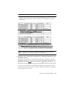
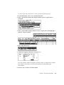
Download StorEdge 3310 Manual
Transcript
Sun StorEdge™ 3310 SCSI Array Installation, Operation, and Service Manual™ Sun Microsystems, Inc. 4150 Network Circle Santa Clara, CA 95054 U.S.A. 650-960-1300 Part No. 816-7290-11 October 2002, Revision 01 Send comments about this document to: [email protected] Copyright © 2002 Dot Hill Systems Corporation, 6305 El Camino Real, Carlsbad, California 92009, USA. All rights reserved. Sun Microsystems, Inc. and Dot Hill Corporation may have intellectual property rights relating to technology embodied in this product or document. In particular, and without limitation, these intellectual property rights may include one or more of the U.S. patents listed at http://www.sun.com/patents and one or more additional patents or pending patent applications in the U.S. and other countries. This product or document is distributed under licenses restricting its use, copying distribution, and decompilation. No part of this product or document may be reproduced in any form by any means without prior written authorization of Sun and its licensors, if any. Third-party software is copyrighted and licensed from Sun suppliers. Parts of the product may be derived from Berkeley BSD systems, licensed from the University of California. UNIX is a registered trademark in the U.S. and in other countries, exclusively licensed through X/Open Company, Ltd. Sun, Sun Microsystems, the Sun logo, AnswerBook2, docs.sun.com, and Solaris are trademarks or registered trademarks of Sun Microsystems, Inc. in the U.S. and in other countries. Federal Acquisitions: Commercial Software - Government Users Subject to Standard License Terms and Conditions. DOCUMENTATION IS PROVIDED “AS IS” AND ALL EXPRESS OR IMPLIED CONDITIONS, REPRESENTATIONS AND WARRANTIES, INCLUDING ANY IMPLIED WARRANTY OF MERCHANTABILITY, FITNESS FOR A PARTICULAR PURPOSE OR NONINFRINGEMENT, ARE DISCLAIMED, EXCEPT TO THE EXTENT THAT SUCH DISCLAIMERS ARE HELD TO BE LEGALLY INVALID. Copyright © 2002 Dot Hill Systems Corporation, 6305 El Camino Real, Carlsbad, Californie 92009, USA. Tous droits réservés. Sun Microsystems, Inc. et Dot Hill Systems Corporation peuvent avoir les droits de propriété intellectuels relatants à la technologie incorporée dans ce produit. En particulier, et sans la limitation, ces droits de propriété intellectuels peuvent inclure un ou plus des brevets américains énumérés à http://www.sun.com/patents et un ou les brevets plus supplémentaires ou les applications de brevet en attente dans les Etats Unis et les autres pays. Ce produit ou document est protégé par un copyright et distribué avec des licences qui en restreignent l'utilisation, la copie, la distribution, et la décompilation. Aucune partie de ce produit ou document ne peut être reproduite sous aucune forme, par quelque moyen que ce soit, sans l'autorisation préalable et écrite de Sun et de ses bailleurs de licence, s'il y ena. Le logiciel détenu par des tiers, et qui comprend la technologie relative aux polices de caractères, est protégé par un copyright et licencié par des fournisseurs de Sun. Des parties de ce produit pourront être dérivées des systèmes Berkeley BSD licenciés par l'Université de Californie. UNIX est une marque déposée aux Etats-Unis et dans d'autres pays et licenciée exclusivement par X/Open Company, Ltd. Sun, Sun Microsystems, le logo Sun, AnswerBook2, docs.sun.com, et Solaris sont des marques de fabrique ou des marques déposées de Sun Microsystems, Inc. aux Etats-Unis et dans d’autres pays. LA DOCUMENTATION EST FOURNIE “EN L'ETAT” ET TOUTES AUTRES CONDITIONS, CONDITIONS, DECLARATIONS ET GARANTIES EXPRESSES OU TACITES SONT FORMELLEMENT EXCLUES, DANS LA MESURE AUTORISEE PAR LA LOI APPLICABLE, Y COMPRIS NOTAMMENT TOUTE GARANTIE IMPLICITE RELATIVE A LA QUALITE MARCHANDE, A L'APTITUDE A UNE UTILISATION PARTICULIERE OU A L'ABSENCE DE CONTREFAÇON. Please Recycle Contents Preface 1. 2. ix Array Overview 1–1 1.1 Introducing the Array Models 1.2 Task Map 1.3 Additional Software Tools Site Planning 1–3 1–4 2–1 2.1 Customer Obligations 2.2 Safety Precautions 2.3 Environmental Requirements 2.3.1 1–1 2–2 2–2 2–3 Electromagnetic Compatibility (EMC) 2.4 Electrical and Power Specifications 2.5 Physical Specifications 2.6 Layout Map 2–3 2–4 2–5 2–5 2.6.1 Rack Placement 2–5 2.6.2 Tabletop Placement 2–6 2.7 Console and Other Requirements 2.8 Preinstallation Worksheet 2–7 2–7 iii 3. Inspecting the Array Package 3.1 Unpacking the Array 3.2 Checking the Package Contents 3.3 4. iv 3–2 3–3 3.2.1 Standard Sun StorEdge 3310 SCSI Array Package 3.2.2 Options/Field Replaceable Units Customer-Provided Cables Rackmounting 3–3 3–4 3–4 4–1 4.1 Required Site and Chassis Preparation 4.2 Cabinet Mounting 4.3 Telco Rackmounting 4.4 5. 3–1 4–3 4–9 4.3.1 Flushmount Configuration 4.3.2 Center-of-Gravity Configuration Powering Up and Checking LEDs Connecting Ports 4–2 4–10 4–13 4–16 5–1 5.1 Connecting Chassis to an AC Power Outlet 5–3 5.2 Connecting the Chassis to DC Power Outlets 5.3 Reviewing Single Versus Dual Drive-Bus Configurations 5.4 Connecting Cables for a Single Bus Configuration 5.5 Connecting Cables for a Dual Bus Configuration 5.6 Connecting SCSI Ports to Host(s) 5–4 5–5 5–8 5–11 5–14 5.6.1 Sun StorEdge 3310 RAID Array 5–14 5.6.2 Sun StorEdge 3310 JBOD Array 5–15 5.7 Cabling Configurations with Two Expansion Units 5–16 5.8 Connecting COM Port to a VT100 Terminal or Solaris Workstation 5.9 Connecting Ethernet Ports to LAN/WAN (Optional) 5–18 Sun StorEdge™ 3310 SCSI Array Installation, Operation, and Service Manual • October 2002 5–18 6. First-Time Configuration 6–1 6.1 Controller Defaults and Limitations 6.2 Battery Operation 6.3 Accessing the Management Tools 6.4 First-Time Controller Configuration 6.5 6–2 6–3 6–3 6–4 6.4.1 Setting Up the Serial Port Connection 6.4.2 Viewing the Initial Firmware Windows 6.4.3 Configuring SCSI Channels as Host or Drive (Optional) 6.4.4 Creating Additional Host IDs (Optional) 6.4.5 Enabling a Solaris Host to Recognize New Devices and LUNs 12 6.4.6 Reviewing Default Logical Drives and RAID Levels 6.4.7 Completing Basic Configuration 6.4.8 Creating Logical Drive(s) (optional) 6.4.9 Changing a Logical Drive Controller Assignment (Optional) 6.4.10 Partitioning a Logical Drive (optional) 6.4.11 Planning for 128 LUNs (Optional) 6.4.12 Mapping Logical Drive Partitions to Host LUNs 6.4.13 Create Device Files for Solaris Environment 6.4.14 Saving Configuration (NVRAM) to a Disk Installing Software 6–5 6–7 6–8 6–10 6– 6–13 6–14 6–14 6–21 6–22 6–26 6–27 6–30 6–31 6–32 6.5.1 Other Supported Software 6.5.2 Enabling VERITAS DMP 6–32 6–32 Contents v 7. 8. Checking LEDs 7.1 LEDs When Array Is First Powered On 7.2 Front-Panel LEDs 7.3 Rear-Panel LEDs 7–1 7–3 7–5 7.3.1 RAID Controller LEDs 7–5 7.3.2 Other Rear-Panel LEDs 7–7 Maintaining and Troubleshooting Your Array 8.1 8.2 8.3 8.4 vi 7–1 8–1 Problem In Seeing the Array on the Host 8–2 8.1.1 RAID LUNs Not Visible to the Host 8–2 8.1.2 JBOD Disks Not Visible to the Host 8–3 Key Screens and Commands 8–3 8.2.1 The Controller Firmware Initial Screen 8.2.2 Main Menu 8.2.3 Quick Installation 8–5 Checking Status Windows 8–5 8–3 8–4 8.3.1 Logical Drive Status Table 8–5 8.3.2 Logical Volume Status Table 8.3.3 SCSI Drive Status Table 8.3.4 SCSI Channel Status Table 8.3.5 Controller Voltage Temperature Status 8.3.6 Viewing SAF-TE Status 8.3.7 Viewing Event Logs on the Screen 8–7 8–8 8–10 8–12 8–13 8–15 Controller Failure Symptoms, Logical Drive Rebuild, and Replacement 16 8.4.1 General Controller Failure Response 8.4.2 Automatic Logical Drive Rebuild 8.4.3 Manual Rebuild 8.4.4 Concurrent Rebuild in RAID (0+1) 8–16 8–17 8–17 8–20 Sun StorEdge™ 3310 SCSI Array Installation, Operation, and Service Manual • October 2002 8– 8.5 9. 8.4.5 Identifying a Failed Drive for Replacement 8.4.6 Restoring Your Configuration (NVRAM) From a File 8.4.7 Fatal Drive Failure Upgrading Firmware 8–25 Review Firmware Upgrade Features 8.5.2 Downloading Firmware Upgrades Installing Spares and FRUs 8–25 8–26 9–1 9.1 Static Electricity Precautions 9.2 Replacing a Drive 9.3 Replacing a Controller Module 9.4 Replacing I/O Modules 9.5 Replacing a Power/Fan Module 9.6 Replacing the Terminator Module 9.7 Replacing the EMU Module 9.8 Replacing the Battery 9–2 9–3 9–4 9–6 9–7 9–8 9–10 9–11 A–1 A.1 Summary of Sun StorEdge 3310 SCSI Array Specifications A.2 Agency Approvals and Standards B. Cabling JBODs 8–23 8–24 8.5.1 A. SCSI Array Specifications 8–20 A–2 A–3 B–1 B.1 A Single Bus JBOD with One Host Connection B.2 A Single Bus JBOD with Two Host Connections B.3 Dual Bus JBOD Configurations B–2 B–3 B–4 B.3.1 Dual Bus, Single Initiator Mode B–5 B.3.2 Dual Bus, Multi-Initiator Mode B–6 Contents vii C. Ethernet Connection C–1 C.1 Setting an IP Address C.2 Setting Up Out-of-Band Management Over Ethernet D. Record of Settings D.1 D.2 C–1 D–1 View and Edit Logical Drives D–2 D.1.1 Logical Drive Information D.1.2 Logical Drive Partition Information View and Edit Host LUNs D.2.1 LUN Mappings D–2 D–4 View and Edit SCSI Drives D.4 View and Edit SCSI Channels D.5 View and Edit Peripheral Devices D.6 Save NVRAM to Disk, Restore from Disk D–5 D–6 D–8 E. Solaris sd.conf Setup and Volume Labels E.1 Editing the sd.conf File E.2 Labeling a Volume viii D–3 D–4 D.3 F. Cable Pinouts C–3 D–8 E–1 E–1 E–3 F–1 F.1 SCSI (Host or Drive) Connector F.2 RJ-45 Connector F.3 DB9 COM port F–1 F–3 F–4 Sun StorEdge™ 3310 SCSI Array Installation, Operation, and Service Manual • October 2002 Preface The Sun™ StorEdge™ 3310 SCSI Array Installation, Operation, and Service Manual gives step-by-step procedures for installing and initially configuring the Sun StorEdge 3310 SCSI array. Field-replacement unit (FRU) procedures are also included. Caution – You should read the Sun StorEdge 3310 SCSI Array Safety, Regulatory, and Compliance Manual before beginning any procedure in this manual. How This Book Is Organized This book contains the following topics: Chapter 1 provides an overview of RAID features. Chapter 2 covers the site planning and basic safety requirements. Chapter 3 provides general procedures for unpacking and inspecting the array. Chapter 4 provides procedures for rackmounting the array. Chapter 5 provides procedures for cabling and for connecting to power and to the network. Chapter 6 provides procedures for a first-time configuration. Chapter 7 describes the front and rear panel LEDs. Chapter 8 provides maintenance and troubleshooting procedures. Chapter 9 provides procedures for installing spares and FRUs. ix Appendix A provides Sun StorEdge 3310 array specifications. Appendix B shows how to cable JBODs to one or more host servers. Appendix C provides Ethernet connection instructions. Appendix D provides tables for recording configuration data. Appendix E provides information about editing the sd.conf file when adding host LUN assignments. Appendix F provides pinout identification for each connector. Using UNIX Commands This document might not contain information on basic UNIX® commands and procedures such as shutting down the system, booting the system, and configuring devices. See one or more of the following for this information: ■ ■ ■ x Solaris Handbook for Sun Peripherals AnswerBook2™ online documentation for the Solaris™ operating system Other software documentation that you received with your system Sun StorEdge™ 3310 SCSI Array Installation, Operation, and Service Manual • October 2002 Typographic Conventions Typeface1 Meaning Examples AaBbCc123 The names of commands, files, and directories; on-screen computer output Edit your.login file. Use ls -a to list all files. % You have mail. AaBbCc123 What you type, when contrasted with on-screen computer output % su Password: AaBbCc123 Book titles, new words or terms, words to be emphasized. Replace command-line variables with real names or values. Read Chapter 6 in the User’s Guide. These are called class options. You must be superuser to do this. To delete a file, type rm filename. 1 The settings on your browser might differ from these settings. Related Documentation Application Title Part Number Late-breaking news Sun StorEdge 3310 SCSI Array Release Notes 816-7292 Best practices Sun StorEdge 3310 SCSI Array Best Practices Manual 816-7293 Safety and compliance Sun StorEdge 3310 SCSI Array Safety, Regulatory, and Compliance Manual 816-7291 Firmware Sun StorEdge 3310 SCSI RAID Firmware Guide 816-7296 Monitoring and configuration software Sun StorEdge 3310 SCSI Configuration Service User Guide 816-7298 Reporting software Sun StorEdge 3310 SCSI Diagnostic Reporter User Guide 816-7722 Command line interface tools Sun StorEdge 3310 SCSI CLI Version 1.0 User Guide 816-7297 Preface xi Technical Support For late-breaking news and troubleshooting tips, review the Sun StorEdge 3310 SCSI Array Release Notes located at: www.sun.com/products-n-solutions/ hardware/docs/Network_Storage_Solutions/Workgroup/3310 For 24-hour access to web-based support solutions, visit the Online Support Center at: www.sun.com/service/online To initiate or check on a USA-only service request, contact Sun support at: 1-800-USA4SUN To obtain international technical support, contact the sales office of a specific country at: www.sun.com/service/contacting/sales.html Accessing Sun Documentation Online All Sun StorEdge 3310 SCSI Array online documentation is located at: http://www.sun.com/products-n-solutions/ hardware/docs/Network_Storage_Solutions/Workgroup/3310 You can order printed copies of the Sun StorEdge 3310 SCSI array manuals at: http://corppub.iuniverse.com/marketplace/sun You can view, print, or purchase a broad selection of Sun documentation, including localized versions, at: http://www.sun.com/documentation xii Sun StorEdge™ 3310 SCSI Array Installation, Operation, and Service Manual • October 2002 Sun Welcomes Your Comments Sun is interested in improving its documentation and welcomes your comments and suggestions. You can email your comments to Sun at: [email protected] Please include the part number (816-7290-11) of your document in the subject line of your email. Preface xiii xiv Sun StorEdge™ 3310 SCSI Array Installation, Operation, and Service Manual • October 2002 CHAPTER 1 Array Overview This chapter provides a brief overview of your Sun StorEdge 3310 SCSI array which is an LVD/SE device. Topics covered in this chapter are: ■ ■ ■ 1.1 “Introducing the Array Models” on page 1-1 “Task Map” on page 1-3 “Additional Software Tools” on page 1-4 Introducing the Array Models The Sun StorEdge 3310 SCSI array models include: ■ ■ ■ A redundant array of independent disks (RAID) with a single controller A RAID with two controllers An expansion unit or JBOD (an array with disks and no controller) Providing up to 432GB RAID based on 36GB drives in an amazingly small footprint (3.5-inch tall by 19 inches wide) storage unit, the Sun StorEdge 3310 SCSI RAID array is high-performance, storage device that contains one or two internal RAID controllers and up to twelve disk drives with SCSI connectivity to the data host. FIGURE 1-1 Front View of a Sun StorEdge 3310 SCSI Array (RAID, Expansion Unit, or JBOD) 1-1 Highly scalable, the RAID-equipped array supports up to two expansion chassis (expansion unit arrays that have a set of drives and no controller) for a total of 36 drives. The RAID array and expansion units connect to the storage devices and consoles via standard serial port, Ethernet, and SCSI connections. FIGURE 1-2 Rear View of a RAID Array Also available is the JBOD (Just a Bunch of Disks) which is an expansion unit connected directly to a host server. FIGURE 1-3 Rear View of an Expansion Unit or JBOD Extensive reliability, availability, and serviceability (RAS) features include redundant components, notification of failed components, and the ability to replace components while the unit is online. The RAID array can be used either as a standalone storage unit or as a building block, interconnected with expansion arrays of the same type. The array can be placed on a tabletop or rackmounted in a server cabinet or expansion cabinet. For information about specifications and agency approvals, refer to Appendix A. 1-2 Sun StorEdge™ 3310 SCSI Array Installation, Operation, and Service Manual • October 2002 1.2 Task Map The following task map outlines the key steps for installing, configuring, and managing the array. Read Release Notes Prepare Site and Plan Configuration Prepare Host System Install Hardware Install Software Before beginning the installation, review the release notes for latebreaking news and updates, located at: www.sun.com/products-n-solutions/hardware/ docs/Network_Storage_Solutions/Workgroup/3310 Prior to installation, you must review important safety guidelines in the Sun StorEdge 3310 SCSI Array Safety, Regulatory, and Compliance Manual (816-7291-11.pdf). To prepare the site and plan the array configuration, refer to: • Sun StorEdge 3310 SCSI Array Installation, Operation, and Service Manual (816-7290-11.pdf) • Sun StorEdge 3310 SCSI Array Best Practices Manual (816-7293-11.pdf). Install up to two HBA adapters in the host system(s). Refer to the documentation that came with your host adapter and system for instructions. Install the StorEdge 3310 SCSI Array on a desktop or in a rack. Refer to this manual for instructions. For additional firmware instructions, refer to Sun StorEdge 3310 SCSI Array RAID Firmware User Guide (816-7296-11.pdf). Optionally install any or all of the software applications from the Professional Storage Manager CD, and use the following guides. • Sun StorEdge 3310 SCSI Configuration Service User Guide (816-7298-11.pdf) • Sun StorEdge 3310 SCSI Diagnostic Reporter User Guide (816-7722-11.pdf) • Sun StorEdge 3310 SCSI CLI User Guide (816-7297-11.pdf) Chapter 1 Array Overview 1-3 1.3 Additional Software Tools The following additional software tools are available on the Sun StorEdge Professional Storage Manager CD-ROM, provided with your array: ■ ■ ■ Sun StorEdge 3310 SCSI Configuration Service, a management and monitoring program Sun StorEdge 3310 SCSI Diagnostic Reporter software, a monitoring utility Sun StorEdge 3310 SCSI CLI, a command line utility to download firmware and to view the event log. The Sun StorEdge 3310 SCSI Array Documentation CD-ROM provides the related user guides with detailed installation and configuration procedures for these tools. For other supported software tools, refer to the Sun StorEdge 3310 SCSI Array Release Notes, located at: www.sun.com/products-n-solutions/ hardware/docs/Network_Storage_Solutions/Workgroup/3310 1-4 Sun StorEdge™ 3310 SCSI Array Installation, Operation, and Service Manual • October 2002 CHAPTER 2 Site Planning This chapter outlines the site-planning requirements and basic safety requirements for the installation and use of Sun StorEdge 3310 SCSI arrays. Customers are asked to complete a “Preinstallation Worksheet” on page 2-7 and to prepare the site for installation according to the worksheet details and the specified site planning requirements. Review the details of this chapter before installing a Sun StorEdge 3310 SCSI array. Topics covered in this chapter are: ■ ■ ■ ■ ■ ■ ■ ■ “Customer Obligations” on page 2-2 “Safety Precautions” on page 2-2 “Environmental Requirements” on page 2-3 “Electrical and Power Specifications” on page 2-4 “Physical Specifications” on page 2-5 “Layout Map” on page 2-5 “Console and Other Requirements” on page 2-7 “Preinstallation Worksheet” on page 2-7 Note – See Sun StorEdge 3310 SCSI Array Release Notes for the current lists of supported operating environments, host platforms, software, and qualified cabinets. 2-1 2.1 Customer Obligations The customer is obliged to inform Sun Microsystems, Inc. of any and all ordinances and regulations that would affect installation. Caution – When selecting an installation site for the Sun StorEdge 3310 SCSI array, choose a location that avoids excessive heat, direct sunlight, dust, or chemical exposure. Such exposure greatly reduces the product’s longevity and might void your warranty. The customer is responsible for meeting all government codes and regulations concerning facilities. The customer is also responsible for compliance with the following requirements: 2.2 ■ Meet all local, national, and international codes covered in this specification. The subjects covered include fire and safety, building, and electrical codes. ■ Document and inform Sun Microsystems, Inc. of any deviations from this specification. Safety Precautions For your protection, observe the following safety precautions when setting up your equipment: ■ Follow all safety precautions and requirements specified in the Sun StorEdge 3310 SCSI Array Safety, Regulatory, and Compliance Manual. ■ A fully loaded array weighs over 50 pounds. Use two people to lift the array to avoid injury. ■ Follow all cautions and instructions marked on the equipment. ■ Ensure that the voltage and frequency of your power source match the voltage and frequency inscribed on the equipment’s electrical rating label. ■ 2-2 Never push objects of any kind through openings in the equipment. Dangerous voltages may be present. Conductive foreign objects could produce a short circuit that could cause fire, electric shock, or damage to your equipment. Sun StorEdge™ 3310 SCSI Array Installation, Operation, and Service Manual • October 2002 2.3 ■ To reduce the risk of electric shock, do not plug Sun products into any other type of power system. Sun products are designed to work with single-phase power systems having a grounded neutral conductor. Contact your facilities manager or a qualified electrician if you are not sure what type of power is supplied to your building. ■ Your Sun product is shipped with a grounding-type (three-wire) power cord. To reduce the risk of electric shock, always plug the cord into a grounded power outlet. ■ Do not use household extension cords with your Sun product. Not all power cords have the same current ratings. Household extension cords do not have overload protection and are not meant for use with computer systems. ■ Do not block or cover the openings of your Sun product. Never place a Sun product near a radiator or heat register. Failure to follow these guidelines can cause overheating and affect the reliability of your Sun product. Environmental Requirements TABLE 2-1 2.3.1 Environmental Specifications Operating Non-Operating Altitude To 3000 meters (9000 feet). To 12,000 meters (36,000 feet) Temperature 5 degrees C to 35 degrees C -40 degrees C to +65 degrees C 10% to 90% @ 40 degrees C (noncondensing) 0 to 93% @ 38degrees C (noncondensing) Humidity Range Electromagnetic Compatibility (EMC) The following is required for all installations: ■ All AC mains and supply conductors to power distribution boxes for both the rackmounted array and the desktop array must be enclosed in a metal conduit or raceway when specified by local, national, and/or other applicable government codes and regulations. ■ The supply conductors and power distribution boxes (or equivalent metal enclosure) must be grounded at both ends. ■ The supplied arrays require voltages within minimum fluctuation. Chapter 2 Site Planning 2-3 ■ 2.4 The facilities voltage supplied by the customer must maintain a voltage of not more than (+/–) 5 percent. The customer facilities must provide suitable surge protection. Electrical and Power Specifications All Sun StorEdge 3310 SCSI arrays require two independent power sources. Each array has two power-supply-and-fan modules for redundancy. Each Sun StorEdge 3310 AC array requires two 115 VAC/15A or two 240 VAC service outlets. All AC power supplies are autoranging and are automatically configured to a range of 90-264 VAC and 47-63 Hz. There is no need to make special adjustments. Each DC array requires two –48 VDC service outlets, and has a input voltage range of –36 VDC to –72 VDC. Note – To ensure power redundancy, be sure to connect the two Sun StorEdge 3310 SCSI power modules to two separate circuits (for example, one commercial circuit and one UPS). TABLE 2-2 2-4 Power Specifications AC power: Voltage and frequency 90 to 264 VAC, 47 to 63 Hz Input current: 5A max Power-supply output voltages: +5 VDC and +12 VDC DC power: –48V DC (–36 VDC to –72 VDC) Sun StorEdge™ 3310 SCSI Array Installation, Operation, and Service Manual • October 2002 2.5 Physical Specifications Use the following physical specifications to plan the location of your array. TABLE 2-3 2.6 Physical Specifications Category Description Dimensions 2U (3.5-in.) height 20-in.chassis depth 17.5-in.(19 in.with ears) width Installation clearances For FRU removal and replacement, 15-in.(37 cm) is required front and back. Cooling clearances 6-in. (15 cm) is required front and back. No cooling clearance is required on the sides or the top and bottom of the array. Layout Map It is helpful to create a sketch or layout map to indicate the exact location for the Sun StorEdge 3310 SCSI array installation as well as the location of the hosts, console, and Ethernet connections that will be connected to it. As you lay out the components, consider the cable lengths that will be used. 2.6.1 Rack Placement Follow these guidelines when preparing a rackmount placement for your system. ■ Ensure that the floor surface is level. ■ Leave enough space in front of the rack to access components for servicing. ■ Leave enough space in back of the rack to access components for servicing. ■ Keep power and interface cables clear of foot traffic. Route cables inside walls, under the floor, through the ceiling, or in protective channels or raceways. Chapter 2 Site Planning 2-5 2.6.2 ■ Route interface cables (excluding fiber-optic cables) away from motors and other sources of magnetic or radio frequency interference. ■ Stay within the cable length limitations. ■ Provide two separate power sources for the array. These power sources must be independent of each other, and each must be controlled by a separate circuit breaker at the power distribution point. Tabletop Placement Sun StorEdge 3310 SCSI arrays can be positioned on a desk or a table. Follow these guidelines when preparing a tabletop placement for your system. 2-6 ■ Choose a desk or a table that can support 50 pounds for one fully-configured array or 100 pounds for two arrays. ■ Do not place the array(s) on the edge of the table. Set the array so that at least 50 percent of the array is inside the table or desk leg support area. Failure to do this may cause the table to tip over. ■ Leave enough space in front and in back of the array to access components for servicing. To remove the components requires a clearance of 15 inches (37 cm) in front and in back of the array. ■ Provide a minimum space of 6 inches (15 cm) in front and in back of the array for adequate airflow. ■ Keep power and interface cables clear of foot traffic. Route cables inside walls, under the floor, through the ceiling, or in protective channels or raceways. ■ Route interface cables away from motors and other sources of magnetic or radio frequency interference. ■ Stay within the cable length limitations. ■ Ensure that the operating system for the array does not exceed the specifications. ■ Use two people to lift the array to avoid injury. The array can weigh up to 50 pounds. ■ Do not place the array in a vertical position. Place the array horizontally. ■ If you are installing two arrays, you can stack one array on top of the other. Do not stack more than two arrays together. ■ Provide two separate power sources for the array. These power sources must be independent of each other, and each must be controlled by a separate circuit breaker at the power distribution point. Sun StorEdge™ 3310 SCSI Array Installation, Operation, and Service Manual • October 2002 2.7 Console and Other Requirements A console (with one serial port or one Ethernet connection) is necessary for installation and configuration of your Sun StorEdge 3310 SCSI array. Refer to the following Preinstallation Worksheet for additional preparation details. 2.8 Preinstallation Worksheet When ordering a Sun StorEdge 3310 SCSI array, complete the following Preinstallation Worksheet and then prepare the site for installation according to the site-planning requirements. You are responsible for ensuring that the site consistently conforms to all stipulated standards, and that necessary peripherals are made available to the engineer during installation. Review the details of your specific survey before installing your Sun StorEdge 3310 SCSI array. Chapter 2 Site Planning 2-7 If necessary, attach or sketch a network diagram to the survey. TABLE 2-4 Preinstallation Worksheet Rackmounting Customers must ensure that the appropriate service outlets are available for installation. Requirements vary. Will the Sun StorEdge 3310 SCSI array be rackmounted? Yes / No • Is the rack supplied by Sun? Yes / No • If yes, include Sun model number: ____ • If not, make/model: _____________________ / _____________________ Does the rack mount: • Front and back? If so, depth? ______ • Center/Telco? ______ What cable lengths are required? _________________ ** Diagram preferred ** Are there any power strips or power sequencers in the rack? Yes / No Are they supplied by Sun? Yes / No If yes, part number: ___________ If not, quantity of plugs/outlets required: __________ / __________ 2-8 IP address Array IP address: ______.______.______.______ Array network mask: ______.______.______.______ Cabling SCSI cable lengths to connect to hosts: _______________ Sun StorEdge™ 3310 SCSI Array Installation, Operation, and Service Manual • October 2002 TABLE 2-5 Host Connectivity Summarized Host Connectivity - Host #1 Host Name: _____________________________________ Host Make/Model: ________________________________ HBA connector types: _____________________________ Cable distance from the array to the host(s): ___________ Operating system: ________________________________ Patches installed: ________________________________ IP addresses: • Network ____________________ • Host ______________________ Host Connectivity - Host #2 Host Name: _____________________________________ Host Make/Model: ________________________________ HBA connector types: _____________________________ Cable distance from the array to the host(s): ___________ Operating system: ________________________________ Patches installed: ________________________________ IP addresses: • Network ____________________ • Host ______________________ Chapter 2 Site Planning 2-9 2-10 Sun StorEdge™ 3310 SCSI Array Installation, Operation, and Service Manual • October 2002 CHAPTER 3 Inspecting the Array Package This chapter gives the general procedure for inspection and reviews the Sun StorEdge 3310 SCSI array package. Topics covered in this chapter are as follows: ■ ■ ■ “Unpacking the Array” on page 3-2 “Checking the Package Contents” on page 3-3 ■ “Standard Sun StorEdge 3310 SCSI Array Package” on page 3-3. ■ “Options/Field Replaceable Units” on page 3-4 “Customer-Provided Cables” on page 3-4 3-1 3.1 Unpacking the Array Follow these guidelines for unpacking the equipment. Caution – Always use two people to remove the unit from its container, to avoid personal injury or damage to the equipment during installation. This unit weighs approximately 50 pounds. 1. Select a suitable area for unpacking. 2. Store all packing material and boxes for possible equipment returns. 3. Check the Contents Sheet in your product package. See “Checking the Package Contents” on page 3-3. The Contents Sheet summarizes the standard contents for your product. 4. Compare the packing slip and the list of parts with the items you received. If the list of parts on your packing slip does not match the items you received, or any items appear damaged, immediately notify your carrier agent and the supplier who prepared your shipment. 5. Carefully examine the cables provided in the package. If any cable appears to be damaged, contact the Technical Service department for an immediate replacement. 6. Check the list of “Customer-Provided Cables” on page 3-4. These are required to complete your installation. Caution – You must purchase or provide 160M-compliant SCSI cables for connecting the Sun StorEdge 3310 SCSI array to host servers. 3-2 Sun StorEdge™ 3310 SCSI Array Installation, Operation, and Service Manual • October 2002 3.2 Checking the Package Contents It is important to inspect your Sun StorEdge 3310 SCSI array packages for standard items as well as purchased options before you begin installation. If any parts are missing or damaged, contact your sales representative immediately. 3.2.1 Quantity Standard Sun StorEdge 3310 SCSI Array Package Item 1 One or more of the following Sun StorEdge 3310 SCSI arrays: • Sun StorEdge 3310 SCSI array with single controller • Sun StorEdge 3310 SCSI array with dual controllers • Sun StorEdge 3310 Expansion Unit or JBOD (a group of disks, no controller) 1 • Sun StorEdge 3310 SCSI Array Contents Sheet • To download and print the latest Sun StorEdge 3310 SCSI array release notes, go to: www.sun.com/products-n-solutions/hardware/docs/ Network_Storage_Solutions/Workgroup/3310 2 CDs in a CD set; one CD for software and one CD for user documentation 1 SCSI jumper cable, 1-foot (30cm), VHD-VHD (for bus setting) 1 SCSI jumper cable, 1.5-foot (45cm), VHD-VHD (if you ordered a JBOD or expansion unit) 1 Serial null modem cable 1 or 2 25-foot (7.5m), CAT5 Ethernet cable per controller in each array 1 Cable adapter, DB9-to-DB25 2 DC power cables if you ordered a DC-powered array 2 AC cord locks in a plastic bag if you ordered an AC-powered array 2 Front-bezel keys in a plastic bag, to secure the front bezel onto the chassis Various Purchased options. These options are ordered at the time of purchase and are integrated into or added to the unit prior to delivery. Chapter 3 Inspecting the Array Package 3-3 3.2.2 Options/Field Replaceable Units Check that you received all field-replaceable units (FRUs) ordered with your Sun StorEdge 3310 SCSI array. For additional FRUs, consult your sales representative. 3.3 FRU Model Number Description F370-5394-01 Event monitoring unit F370-5396-01 I/O module, LVD, expansion unit or JBOD F370-5397-01 I/O module, LVD, RAID F370-5403-01 Controller module, 512 memory, battery, 2U LVD F370-5399-01 Terminator module F370-5422-01 Drive module, 36GB LVD, 10K RPM F370-5398-01AC AC power and fan module, 2U F370-5527-01DC DC power and fan module, 2U F370-5533-01 Battery, LVD F370-5405-01 Cable, LVD, 1-foot, jumper F370-5528-01 Cable, LVD, 1.5-foot, expansion F370-5393-01 Box, 2U, JBOD, LVD F370-5524-01 Box, 2U, RAID, LVD XTA-3310-DC-KIT Power and fan module, 2U, DC XTA-3310-RK-19M Kit, rackmount, 2U, 19-in. wide, 18- to 28-in. deep XTA-3310-RK-19L Kit, Rackmount, 2U, 19-in. wide, 28- to 36-in. deep XTA-3310-RK-19C Kit, Telco rackmount center mount, 2U, 19-in wide XTA-3310-RK-19F Kit, Telco rackmount flush mount, 2U, 19-in wide Customer-Provided Cables Customers must provide the following cables. ■ Two 3-prong AC power cables if you have an AC-powered array. ■ One Ultra 160 SCSI cable per host to connect a host to a RAID array, Expansion Unit or JBOD; up to two host cables might be needed per array. To obtain qualified cables, consult your Sun sales representative. 3-4 Sun StorEdge™ 3310 SCSI Array Installation, Operation, and Service Manual • October 2002 CHAPTER 4 Rackmounting This chapter describes the two types of rackmount equipment available to purchase and install. The array is easily installed into a rack or cabinet. Topics covered in this chapter are: ■ ■ ■ ■ “Required Site and Chassis Preparation” on page 4-2 “Cabinet Mounting” on page 4-3 “Telco Rackmounting” on page 4-9 ■ “Flushmount Configuration” on page 4-10 ■ “Center-of-Gravity Configuration” on page 4-13 “Powering Up and Checking LEDs” on page 4-16 4-1 4.1 Required Site and Chassis Preparation Tip – These instructions can save you a lot of time read them carefully. The entire assembly procedure should take less than thirty minutes if you follow all the instructions provided. Before rackmounting, be sure to check your site location and confirm that you have cables with adequate lengths to connect to servers and to power outlets. Caution – We recommend that two people install each Sun StorEdge 3310 SCSI array. If you only have one person to perform the installation, you should remove the power supplies and hard disk drives before installing the array, and if possible position the array on top of another device or shelf in the rack to hold the unit as you attach all the brackets. Caution – Do not use any power tools with any procedures. Power tools may strip or damage connections. Note – To reduce the weight of the array during the rackmounting procedure, see “Installing Spares and FRUs” on page 9-1 for instructions on removing drives or power supplies. A fully populated array weighs over 50 pounds; an array without drives and power supplies weighs about 30 pounds. You can now proceed with the power and cabling procedures. Perform all steps in the order given. The following tools are used to complete this procedure: ■ ■ 4-2 Medium Phillips head screwdriver Allen wrenches (provided for 6 mm cap screws and #12–24 socket cap screws) Sun StorEdge™ 3310 SCSI Array Installation, Operation, and Service Manual • October 2002 4.2 Cabinet Mounting This section explains how to mount the Sun StorEdge 3310 SCSI array using adjustable mounting brackets for two distinct depth ranges. FIGURE 4-1 Rackmounted Cabinet Array With Chassis Ears and Bezels Removed Before mounting the Sun StorEdge 3310 SCSI array into a 19-inch cabinet, check the following parts list and then refer to FIGURE 4-2 during installation. Note – Keep all hardware items in plastic bags until you are ready to use them. This enables you to correctly identify the screws and avoid confusion. The following tables list the major components and fasteners provided in the 19-inch rackmount kits. Chapter 4 Rackmounting 4-3 . TABLE 4-1 XTA-3310-RK-19M: 22- to 28-in. Deep Cabinet Rackmount Kit Major Components Fasteners Qty. Part Number Description Qty. Part Number Description 2 71-00000552 side brackets 16 01-00000006 #8 – 32.x 3/16-in. flathead screws 2 71-00000554 rear brackets 8 01-09010300 #8 – 32 x 1/4-in. panhead screws 10 01-50200300 #10 – 32 x 3/8-in. panhead screws 10 02-80002300 #10 – flat washers 4 01-00000083 6mm socket cap screws 4 01-00000084 6mm panhead screws or 71-00000621 1 09-00000064 rear brackets with flanges** Allen wrench* * 5mm wrench for 6mm socket cap screws ** The U-shaped flanges support the side brackets and eliminate the need for a second person to support the array while assembling and tightening screws. TABLE 4-2 XTA-3310-RK-19L: 28- thru 36-In. Deep Cabinet Rackmount Kit Major Components Fasteners Qty. Part Number Description Qty. Part Number Description 2 71-00000553 side brackets 16 01-00000006 #8 – 32 x 3/16-in. flathead screws 2 71-00000555 rear brackets 16 01-09010300 #8 – 32 x 1/4-in. panhead screws 10 01-50200300 #10 – 32 x 3/8-in. panhead screws 10 02-80002300 #10 washers 4 01-00000083 6mm socket cap screws 4 01-00000084 6mm panhead screws or 71-00000622 1 09-00000064 rear brackets with flanges** Allen Wrench* * 5mm wrench for 6mm socket cap screws ** U-shaped flanges support the side brackets and eliminate the need for a second person to support the array while assembling and tightening screws. 4-4 Sun StorEdge™ 3310 SCSI Array Installation, Operation, and Service Manual • October 2002 #10 flat washers and #10-32 x 3/8 panhead screws ** (in four places) Rear bracket connected to rack Threaded holes (four) #8-32 x 1/4-inch panhead screws (four minimum) Chassis #10-32 x 3/8-inch screws** (in four places) #8-32 x 3/16-inch flathead screws (four minimum) Side bracket connected to each side of chassis FIGURE 4-2 Cabinet Rackmount (22- to 28-Inch Deep Rack in a 19-Inch Wide Cabinet) * Alternate flanged rear brackets support the side brackets and enable a easy one-person installation. ** Alternate screws can be used with the appropriate racks: 5mm x 6mm panhead screws or 6mm x 6mm cap screws. Chapter 4 Rackmounting 4-5 Caution – Do not use any power tools with any procedures. Power tools can strip or damage connections. 1. Determine where the array will be installed. To plan the correct location in the appropriate Sun racks, refer to the 805-4748-29 Rackmount Placement Matrix (RPM) which is available at: www.sun.com/products-n-solutions/hardware/docs/ Network_Storage_Solutions/Cabinets_and_Enclosures/index.html Install the first array at the bottom of the rack, and install each subsequent chassis above the previous one unless otherwise indicated in the RPM manual. 2. Before rackmounting, be sure to check your site location and confirm that you have cables with adequate lengths to connect to servers and to power outlets. 3. Remove bezel (front faceplate) and the two plastic ear caps from the front of the chassis. Note – Keep all hardware items in plastic bags until you are ready to use them. This enables you to correctly identify of the screws and avoid confusion. 4. Attach the side brackets to the left and right sides of the chassis Attach up to eight #8-32 x 3/16-inch flathead machine screws on each side to allow some adjustment to the placement. Use the alignment marks (depth in inches) stamped into the side brackets to position the brackets and screws. FIGURE 4-3 Side Bracket With Alignment Marks 5. Use a total of four screws and four washers to attach the rear brackets to the rear vertical posts (two screws to attach each bracket to a post). 4-6 Sun StorEdge™ 3310 SCSI Array Installation, Operation, and Service Manual • October 2002 a. Insert a minimum of four #8-32 x 1/4-inch panhead screws through the side bracket slots and through the rear bracket holes. b. Attach each rear bracket with two #10-32 x 3/8-inch panhead machine screws with #10 washers or two 6mm panhead screws. A minimum of four #8-32 x 1/4-inch panhead screws Rear bracket Side bracket FIGURE 4-4 Rear and Side Brackets Assembled Use the appropriate type of screw for the posts: ■ Four #10-32 x 3/8-inch panhead machine screws with #10 washers ■ Four 6mm panhead screws 6. Lift the chassis and slide the side brackets into the rear brackets, which are attached to the rear posts. Adjust the depth of these brackets so that the rear slotted cutouts on the side brackets align with the four PEM nuts in the rear brackets. Chapter 4 Rackmounting 4-7 7. Attach each side bracket to a rear bracket (see FIGURE 4-4): To connect the rear brackets and side brackets of a 22- to 28-inch deep rack, use a total of: ■ Eight #8-32 x 1/4-inch panhead screws ■ Four #10-32 x 3/8-inch panhead screws ■ Four #10 flat washers To connect the rear and side brackets of a 28- to36-inch deep rack, use a minimum of four each and up to a total of: ■ Sixteen #8-32 x 1/4-inch panhead screws ■ Four #10-32 x 3/8-inch panhead screws ■ Four #10 flat washers 8. Attach and secure the array’s front mounting ears with four appropriate screws (two screws into each ear): ■ Four #10-32 x 3/8-inch panhead screws or ■ Four 6mm x6 socket cap screws 9. Remount all drives and power/fan modules into the array. 10. Attach the two plastic ear caps and the bezel back onto the front of the chassis. 11. Connect power cables to the chassis, power up, and check for proper operation of the LEDs. Refer to “Powering Up and Checking LEDs” on page 4-16. 4-8 Sun StorEdge™ 3310 SCSI Array Installation, Operation, and Service Manual • October 2002 4.3 Telco Rackmounting This section provides the procedure for mounting a Sun StorEdge 3310 SCSI array using Telco hardware. FIGURE 4-5 Rackmounted Telco Array With Chassis Ears and Bezels Removed The following tools are used to complete this procedure: ■ Medium Phillips head screwdriver ■ Allen head wrench (provided; used with 6mm screws and #12-24 x 3/8-inch socket head screws) Caution – Do not use any power tools with any procedures. Power tools can strip or damage connections. Chapter 4 Rackmounting 4-9 4.3.1 Flushmount Configuration Before mounting the Sun StorEdge 3310 SCSI array into a 19-inch cabinet, check the following parts list and then refer to FIGURE 4-6 during installation. The following table lists the major components and fasteners required to assemble the Telco 19-inch wide flushmount racks. TABLE 4-3 XTA-3310-RK-19F: Telco Flushmount Rackmount Kit Major Component Fasteners Qty. Part Number Description Qty. Part Number Description 2 71-00000492 Rear brackets 10 01-09010300 #8-32 x 1/4 in. panhead screws 10 28-FLAT-8 #8 washers 8 01-50200300 #10-32 x 3/8 in. panhead screws 8 02-80002300 #10 washers 8 02-09002340 #12 washers 4 01-00000083 6mm x 6 socket cap screws 8 01-00000084 6mm x6 panhead screws 8 01-00000093 5mm x6 panhead screws 8 01-12020300 #10-24 x 3/8 in. panhead screws 8 01-00000092 #12-24 x 3/8 in. socket cap screws 1 09-00000064 Allen wrench * 1 09-00000063 Allen wrench ** * 5mm wrench for 6mm socket cap screws. ** 5/32 wrench for #12-24 socket cap screws. Perform the following installation steps for a Telco flushmount rack configuration (see FIGURE 4-6). 1. Determine where the array will be installed. To plan the correct location in the appropriate Sun racks, refer to the 805-4748-29 Rackmount Placement Matrix (RPM), which is available at: www.sun.com/products-n-solutions/hardware/docs/ Network_Storage_Solutions/Cabinets_and_Enclosures/index.html Install the first array at the bottom of the rack, and install each subsequent chassis above the one below unless otherwise indicated in the RPM manual. 4-10 Sun StorEdge™ 3310 SCSI Array Installation, Operation, and Service Manual • October 2002 2. Before rackmounting, be sure to check your site location and confirm that you have cables with adequate lengths to connect to servers and to power outlets. 3. Remove bezel (front faceplate) and two plastic ear caps from the front of the chassis. Note – Keep all hardware items in plastic bags until you are ready to use them. This enables you to correctly identify of the screws and avoid confusion. 4. Attach the rear brackets to the left and right sides of the chassis. Use four #8-32 x 1/4-inch panhead machine screws with #8 washers per bracket. 5. Attach the unit to the Telco rack, using four 6mm socket cap screws through the chassis ears. Use the appropriate type of screws for the posts: ■ #10 – 32 x 3/8-inch panhead screws or ■ 5mm x6 panhead screws or #12-24 cap screws 6. Reinstall all drive modules and power/fan modules into the array if they were removed. 7. Attach (snap) the two plastic ear caps and bezel back onto the front of the chassis. 8. Connect the power cables to the chassis, power up, and check for proper operation of the LEDs. For details about the LEDs, refer to “Powering Up and Checking LEDs” on page 4-16. Chapter 4 Rackmounting 4-11 Side brackets in 2 places #8 washers in 10 places #8-32 x1/4-inch panhead screws in 10 places Telco rack #10-32 x 3/8-inch screws with #10 washers or 6mm panhead screws in 4 places 6mm socket cap screws in 4 places FIGURE 4-6 4-12 Flushmount Assembly Sun StorEdge™ 3310 SCSI Array Installation, Operation, and Service Manual • October 2002 4.3.2 Center-of-Gravity Configuration The following table lists the major components and fasteners required to assemble the Telco 19-inch wide center-of-gravity rack. TABLE 4-4 XTA-3310-RK-19C: Telco Center-of-Gravity Rackmount Kit Major Components Fasteners Qty. Part Number Description Qty. Part Number Description 4 71-00000491 Side brackets 24 01-09010300 #8-32 x 1/4 in. panhead screws 24 28-FLAT-8 10 01-50200300 #10-32 x 3/8 in. panhead screws 10 02-80002300 #10 washers 10 02-09002340 #12 washers 10 01-00000083 6mm x 6 socket cap screws 10 01-00000084 6mm x 6 panhead screws 10 01-00000093 5mm x 6 panhead screws 10 01-12020300 #10-24 x 3/8 in. panhead screws 8 01-00000092 #12-24 x 3/8 in. socket cap screws 1 09-00000064 Allen wrench* 1 09-00000063 Allen wrench** #8 washers * 5mm wrench for 6mm socket cap screws ** 5/32 wrench for #12-24 socket cap screws Perform the following installation steps for a Telco center-of-gravity rack configuration (see FIGURE 4-7). 1. Determine where the array will be installed. To plan the correct location in the appropriate Sun racks, refer to the 805-4748-29 Rackmount Placement Matrix (RPM), which is available at: www.sun.com/products-n-solutions/hardware/docs/ Network_Storage_Solutions/Cabinets_and_Enclosures/index.html Install the first array at the bottom of the rack, and install each subsequent chassis above the one below unless otherwise indicated in the RPM manual. 2. Before rackmounting, be sure to check your site location and confirm that you have cables with adequate lengths to connect to servers and to power outlets. Chapter 4 Rackmounting 4-13 Note – Keep all hardware items in plastic bags until you are ready to use them. This enables you to correctly identity of the screw sizes and avoid confusion. 3. Remove the bezel (front faceplate) and two plastic ear caps from the front of the chassis. 4. Attach the two side brackets to each side of the chassis: Allow for the depth of the rack, and allow for the distance you want the chassis to extend forward in the rack. Attach the front brackets first. Use up to six #8-32 x 1/4-inch panhead machine screws for each front side bracket, using the mounting holes available. (Use four screws as a minimum.) Then mount the front brackets to the Telco rack using step 5. Next, use four #8-32 x 1/4-inch panhead screws with #8 washers for each rear side bracket, and use step 5 to mount to Telco rack. 5. Attach the chassis to the Telco rack, by inserting eight or more 6mm screws through the mounting holes located on both sides of the brackets and into the frame. Use the appropriate type of screws for the ports: ■ #10 – 32 x 3/8-inch panhead screws with #8 washers or ■ 5mm x6 panhead screws or #12-24 cap screws 6. Reinstall all drive modules and power/fan modules into the array if they were removed. 7. Attach (snap) the two plastic ear caps and the bezel back onto the front of the chassis. 8. Connect power cables to the chassis, power up, and check for proper operation of the LEDs. For details about the LEDs, refer to “Powering Up and Checking LEDs” on page 4-16. 4-14 Sun StorEdge™ 3310 SCSI Array Installation, Operation, and Service Manual • October 2002 Rear brackets in two places Eight #8 washers Eight #8-32 x 1/-inch panhead screws (Total of 16 each) Front brackets in two places Telco rack #10-32 x 3/8-inch screws or 6mm panhead screws (in eight places) #10 washers in eight places FIGURE 4-7 Center-of-Gravity Assembly Chapter 4 Rackmounting 4-15 4.4 Powering Up and Checking LEDs Perform the initial check of the array according to the following procedure. 1. Connect two AC (or DC) power cables to the power/fan modules on the rear of the array. 2. Power on the array by pressing the 1 on each power switch. 3. Check for the following LED activity: Front-panel LEDs: All front LEDs turn solid green to indicate good operation. Drive LED 1 LED 4 LED 2 LED 5 LED 3 LED 6 Drive LED 7 LED 10 LED 8 LED 11 LED 9 LED 12 Disk 1 Disk 4 Disk 7 Disk 10 Disk 2 Disk 5 Disk 8 Disk 11 Disk 3 Disk 6 Disk 9 Disk 12 FIGURE 4-8 POWER FAN TEMP EVENT RESET Push button Front-Panel with LEDs Displayed Rear-Panel LEDs I/O module PS ERROR PS TERM TERM CH 0 SB CH 3 SB SNGL BUS CONF SNGL CH 1 CH 2 DUAL BUS CONF DB POWER POWER + Activity <...> COM 10/100 BASE-T COM 10/100 BASE-T + Activity Power/fan module FIGURE 4-9 4-16 Controller module EMU E V E N T 1 EMU E V E N T 2 <...> Event module Rear-Panel with LEDs Displayed Sun StorEdge™ 3310 SCSI Array Installation, Operation, and Service Manual • October 2002 If you power up without attaching the SCSI bus configuration cable, and you are not connected to a server, you should see the LED conditions described in the following table. TABLE 4-5 LED Status When the Array is First Powered On Description Status I/O module: ERROR LED TERM LED SNGL LED Blinking green (no bus configuration; invalid state) Solid green (auto termination enabled) Inactive (no bus configuration; invalid state) Controller module: ACTIVITY Inactive (controller not busy) Center LED (status symbol) Slow blinking green: good primary controller Solid green: good secondary controller Right-side LED (battery symbol) Blinking green if battery is charging Solid green if battery is fully charged Power/fan module LEDs Solid green Event module LEDs Solid green Note – If you power up to check the array, power off the array before you proceed with cabling the array to the host servers. Chapter 4 Rackmounting 4-17 4-18 Sun StorEdge™ 3310 SCSI Array Installation, Operation, and Service Manual • October 2002 CHAPTER 5 Connecting Ports This chapter provides procedures for cabling the Sun StorEdge 3310 SCSI array for single or dual bus configurations and for connecting the array to power and to network devices. The topics covered in this chapter are as follows: ■ ■ ■ ■ ■ ■ ■ ■ ■ “Connecting Chassis to an AC Power Outlet” on page 5-3 “Connecting the Chassis to DC Power Outlets” on page 5-4 “Reviewing Single Versus Dual Drive-Bus Configurations” on page 5-5 “Connecting Cables for a Single Bus Configuration” on page 5-8 “Connecting Cables for a Dual Bus Configuration” on page 5-11 “Connecting SCSI Ports to Host(s)” on page 5-14 “Cabling Configurations with Two Expansion Units” on page 5-16 “Connecting COM Port to a VT100 Terminal or Solaris Workstation” on page 5-18 “Connecting Ethernet Ports to LAN/WAN (Optional)” on page 5-18 Before you connect the Sun StorEdge 3310 SCSI array to the network, position the Sun StorEdge 3310 SCSI array in the rack or in a location where it will reside on the network. Caution – When positioning the array, do not block the air vents at the front or back of the unit. Follow all safety precautions specified in the Sun StorEdge 3310 Safety, Regulatory, and Compliance Manual. Caution – When you power off the array, wait five seconds before you power it back on. If you power the array off and on too quickly, a race condition might occur. 5-1 FIGURE 5-1 identifies a typical series of hardware connections required when you install an array. These procedures are designed for a redundant configuration. Application/Data Servers & Consoles SCSI Device Connections 3 Host/Drive I/O Module Power OFF/ON 2 Bus Cabling Event Monitoring Unit (EMU) PS ERROR TERM TERM CH 0 SB CH 3 SB PS SNGL BUS CONF SNGL CH 1 CH 2 DUAL BUS CONF DB POWER POWER + Activity <...> COM 10/100 BASE-T COM 10/100 BASE-T + Activity 1 Power Outlet Controller EMU E V E N T 1 EMU E V E N T 2 <...> 4 5 Termination Module 10/100 Base-T Ethernet DB-9 Terminal Port WAN SCSI Devices Servers & Consoles Network Management Console FIGURE 5-1 5-2 Typical Sequence of Installation Steps Sun StorEdge™ 3310 SCSI Array Installation, Operation, and Service Manual • October 2002 5.1 Connecting Chassis to an AC Power Outlet When you connect the AC power cords, you should install the provided two cord locks at the same time. To connect the AC power cords, perform the following procedure. 1. Connect an appropriate AC power cable to the first power supply and to a power outlet. The provided AC cord locks are used to securely fasten the AC cable connectors. Caution – For AC power: If the array is connected to AC power sources not within the designated 90–135, 180–265 VAC PFC range, damage might occur to the unit. Note – To ensure power redundancy, be sure to connect the two power supply modules to two separate circuits (for example, one commercial circuit and one UPS). 2. Use a screwdriver to remove the screw from one of the two cord locks provided. 3. Turn the thumbscrew of the green ejector handle counterclockwise to release the handle. 4. Pull the green ejector handle of the first power supply forward, and slide the cord lock around the handle and around the AC power connector on the power supply. The cord lock fits very snugly around the power cable connector. Chapter 5 Connecting Ports 5-3 Picture of installed cord lock 5. Slide the cord lock screw through the cord lock holes, and tighten the screw with a screwdriver. Close the green ejector handle, and turn the thumbscrew clockwise to close the handle. 6. Repeat steps 2 through 5 for the second cord lock and second power cable. 5.2 Connecting the Chassis to DC Power Outlets Two CD power cords are packaged with each DC array. To connect the DC power cords, perform the following procedure. 1. Connect a DC power cable to the first power supply and to a power outlet. Caution – For DC power: If the Sun StorEdge 3310 SCSI array is connected to DC power sources not within the designated –48V DC (–36 VDC to –72 VDC) range, damage might occur to the unit. Note – To ensure power redundancy, be sure to connect the two power supply modules to two separate circuits (for example, one commercial circuit and one UPS). 2. Tighten the cable locking screws to attach the cable securely to the power supply power outlet. 3. Connect the second power cable to the second power supply and to a second power outlet. Tighten the cable locking screws. If one power supply fails, the second power supply automatically takes the full load. 5-4 Sun StorEdge™ 3310 SCSI Array Installation, Operation, and Service Manual • October 2002 5.3 Reviewing Single Versus Dual Drive-Bus Configurations The drive-bus configuration determines how drives and drive IDs are assigned to drive channels on the controller. A single bus configuration assigns all disk drive IDs in a controller to one channel (typically CH 0 for the RAID array and CH 2 for an expansion unit). A dual bus configuration assigns half the disk drive IDs to CH 0 and the other half to CH 2 in the RAID array, and then typically adds additional disk drive IDs to both CH 0 and CH2 when it is connected to an expansion unit. The following figures illustrate the six standard cabling scenarios for a 12-drive array: 0 1 Host 2 3 FIGURE 5-2 Host Configuration #1: Single Bus Configuration With Two Hosts 0 1 Host 2 3 FIGURE 5-3 Host Configuration #2: Dual Bus Configuration With Two Hosts Chapter 5 Connecting Ports 5-5 0 1 Host 2 3 FIGURE 5-4 Configuration #3: Dual Bus Configuration With One Host Expansion Unit 0 1 2 3 FIGURE 5-5 Host Configuration #4: Dual Bus Configuration With One Expansion Unit Expansion Unit 0 Expansion Unit 1 2 3 FIGURE 5-6 Host Configuration #5: Single Bus Configuration with Two Expansion Units Expansion Unit 0 1 Host 2 3 FIGURE 5-7 5-6 Host Configuration #6: Single Bus RAID Connected to One Expansion Unit Sun StorEdge™ 3310 SCSI Array Installation, Operation, and Service Manual • October 2002 Each drive channel can have up to 16 IDs (0 to 15); ID 6 and ID 7 are reserved for internal connections. Caution – A maximum of 16 drive IDs is allowed per channel. Therefore, do not connect a dual bus Channel 0 or Channel 2 (6 IDs) to a single bus expansion unit (12 IDs). On the rear panel of each RAID array on the I/O module, the SB icon is displayed next to the CH 0 port and the SCSI SNGL BUS CONF port to indicate where to connect the SCSI jumper cable for a single bus configuration. Similarly, the DB icon is displayed next to the CH 2 port and the DUAL BUS CONF port to indicate where to connect the SCSI jumper cable for a dual bus configuration. SB = Single bus configuration DB = Dual bus configuration FIGURE 5-8 Single Bus and Dual Bus Icons On the rear panel of each expansion unit, the SB icon indicates where to connect the jumper cable for a single bus configuration. The SCSI IDs are also displayed on the lower inside-front edge of the chassis. These IDs are automatically assigned and appear in the RAID controller status tables. FIGURE 5-9 DUAL/SNGL DUAL/SNGL DUAL/SNGL DUAL/SNGL CH2-ID0 CH0-ID0 CH2-ID3 CH0-ID3 CH0-ID0 CH0-ID8 CH0-ID3 CH0-ID11 CH2-ID1 CH0-ID1 CH2-ID4 CH0-ID4 CH0-ID1 CH0-ID9 CH0-ID4 CH0-ID12 CH2-ID2 CH0-ID2 CH2-ID5 CH0-ID5 CH0-ID2 CH0-ID10 CH0-ID5 CH0-ID13 Disk Drive IDs Displayed Inside the Lower Edge of the Chassis Chapter 5 Connecting Ports 5-7 5.4 Connecting Cables for a Single Bus Configuration A single bus I/O configuration assigns all disk drive IDs in a chassis (RAID or expansion unit) to one channel. This configuration is convenient administratively if you want to assign all RAID array drive IDs to Channel 0, and assign all expansion unit drive IDs to Channel 2. 1. To configure a RAID array as a single bus configuration, connect the SCSI jumper cable between the SCSI ports labeled “CH 0” and “SNGL BUS CONF” as shown in FIGURE 5-10. ERROR TERM SNGL TERM CH 0 CH 1 FIGURE 5-10 SB CH 3 CH 2 SB SNGL BUS CONF DUAL BUS CONF DB Single Bus Connection: All Drives are Assigned to a Single Channel (CH 0) 2. To configure an expansion unit as a single bus configuration, connect the SCSI jumper cable between SCSI ports (lower left and upper right ports), as shown in FIGURE 5-11. ERROR TERM TERM B B FIGURE 5-11 SB SB A A Cabling for Single Bus Expansion Unit Caution – A maximum of 16 drive IDs is allowed per channel. Therefore, with a 12drive array, do not connect a dual bus Channel 0 or Channel 2 (6 IDs) to a single bus expansion unit (12 IDs). 5-8 Sun StorEdge™ 3310 SCSI Array Installation, Operation, and Service Manual • October 2002 3. (Optional) Use a SCSI cable to connect a RAID array (Channel 2 port) to an expansion unit (lower right port). The configuration in FIGURE 5-12 shows a RAID array with all its drive IDs assigned to Channel 0, and an expansion unit with all its drive IDs assigned to Channel 2. ERROR TERM SNGL TERM CH 0 SB CH 3 CH 2 CH 1 SNGL BUS CONF SB DUAL BUS CONF DB RAID Array Host Servers ERROR TERM TERM B B A SB A SB Expansion unit FIGURE 5-12 Typical Single Bus Configuration Based on the configuration in FIGURE 5-12, the default drive IDs for a 12-drive single bus configuration are shown in FIGURE 5-13 and FIGURE 5-14. (ID6 and ID7 are reserved for host HBAs.) Disk 1 CH0-ID0 Disk 4 CH0-ID3 Disk 7 CH0-ID8 Disk 10 CH0-ID11 Disk 2 CH0-ID1 Disk 5 CH0-ID4 Disk 8 CH0-ID9 Disk 11 CH0-ID12 Disk 3 CH0-ID2 Disk 6 CH0-ID5 Disk 9 CH0-ID10 Disk 12 CH0-ID13 FIGURE 5-13 RAID Array - Single Bus Configuration, Default IDs Chapter 5 Connecting Ports 5-9 Disk 1 CH2-ID0 Disk 4 CH2-ID3 Disk 7 CH2-ID8 Disk 10 CH2-ID11 Disk 2 CH2-ID1 Disk 5 CH2-ID4 Disk 8 CH2-ID9 Disk 11 CH2-ID12 Disk 3 CH2-ID2 Disk 6 CH2-ID5 Disk 9 CH2-ID10 Disk 12 CH2-ID13 FIGURE 5-14 Expansion Unit - Single Bus Configuration, Default IDs The IDs are also displayed on the lower inside-front edge of the chassis. These IDs are automatically assigned and appear in RAID controller status tables. 4. Connect your RAID array (SCSI Channel 1 and 3 ports) to one or two host servers with SCSI cables. SCSI ports for Channels 1 and 3 are assigned as host channels by default. 5-10 Sun StorEdge™ 3310 SCSI Array Installation, Operation, and Service Manual • October 2002 5.5 Connecting Cables for a Dual Bus Configuration A dual bus configuration assigns half the disk drives to one channel and the other to the second channel. This configuration can be helpful when you want to use one set of drives to mirror the second set with drives configured as RAID 1 drives. 1. To create a dual bus configuration on a RAID array, use the SCSI jumper cable to connect the CH 2 port to the DUAL BUS CONF port. Six IDs are assigned to CH 0, and six IDs are assigned to CH 2 in a 12-drive array. TERM ERROR SNGL TERM CH 0 SB CH 2 CH 1 FIGURE 5-15 CH 3 SB SNGL BUS CONF DUAL BUS CONF DB RAID Dual Bus Configuration In the dual bus JBOD configuration, no jumper cable is required. ERROR TERM TERM B B FIGURE 5-16 SB SB A A Expansion Unit Dual Bus Configuration 2. (Optional) Use a SCSI cable to connect a RAID array (Channel 2 port) to an expansion unit lower input port. In FIGURE 5-17, RAID Channels 0 and 2 are expanded into the expansion unit, in a dual bus configuration set up on the RAID array and kept by default for the expansion unit. Chapter 5 Connecting Ports 5-11 Host Servers ERROR TERM SNGL TERM CH 0 SB CH 3 CH 2 CH 1 SB SNGL BUS CONF DUAL BUS CONF DB RAID array ERROR TERM TERM B B (Default Dual Bus Configuration) SB SB A A Expansion unit FIGURE 5-17 Dual Bus Configuration with One RAID Array and One Expansion Unit Caution – A maximum of 16 drive IDs is allowed per channel. Therefore, with a 12drive array, do not connect a dual bus Channel 0 or Channel 2 (6 IDs) to a single bus expansion unit (12 IDs). The dual bus configuration shown in the preceding figure assigns half the IDs from the RAID and the expansion unit to Channel 0, and the other half to Channel 2. The “SINGLE BUS CONF” port is a Channel 2 expansion port in a dual bus configuration. 3. Based on the configuration shown in FIGURE 5-17, the default drive IDs for a dual bus configuration are shown in the following figures. ID6 and ID7 are reserved and are not available for drive IDs. The IDs are also displayed on the lower inside edge of the chassis. These IDs are automatically assigned and appear in RAID controller status tables. 5-12 Sun StorEdge™ 3310 SCSI Array Installation, Operation, and Service Manual • October 2002 Disk 1 CH2-ID0 Disk 4 CH2-ID3 Disk 7 CH0-ID0 Disk 10 CH0-ID3 Disk 2 CH2-ID1 Disk 5 CH2-ID4 Disk 8 CH0-ID1 Disk 11 CH0-ID4 Disk 3 CH2-ID2 Disk 6 CH2-ID5 Disk 9 CH0-ID2 Disk 12 CH0-ID5 FIGURE 5-18 RAID Array: Dual Bus Configuration, Default IDs Disk 1 CH2-ID8 Disk 4 CH2-ID11 Disk 7 CH0-ID8 Disk 10 CH0-ID11 Disk 2 CH2-ID9 Disk 5 CH2-ID12 Disk 8 CH0-ID9 Disk 11 CH0-ID12 Disk 3 CH2-ID10 Disk 6 CH2-ID13 Disk 9 CH0-ID10 Disk 12 CH0-ID13 FIGURE 5-19 Expansion Unit: Dual Bus Configuration, Default IDs 4. Connect your RAID array (SCSI Channel 1 and 3 ports) to two host servers with SCSI cables. SCSI ports for Channels 1 and 3 are assigned as host channels by default. Chapter 5 Connecting Ports 5-13 5.6 Connecting SCSI Ports to Host(s) By default, channels 1 and 3 (the upper middle SCSI port and lower left SCSI port on the I/O module) are host channels. The array can be connected to a host in one of the two following ways: ■ By means of a Sun StorEdge 160 MB/second PCI Dual Ultra3 SCSI host adapter part number X6758A, installed in a host ■ By means of a qualified and supported onboard single-ended, 40 MB/second SCSI server-embedded SCSI controller Connect the array to one or two hosts with SCSI cables. See the Sun StorEdge 3310 SCSI Array Release Notes for a list of the supported cables. 5.6.1 Sun StorEdge 3310 RAID Array The SCSI specification states that the maximum bug length for Ultra3 SCSI is 25 meters for point-to-point connections. The Sun StorEdge 3310 RAID array uses a point-to-point implementation. Each channel connector is on a separate physical SCSI bus. Taking into account the internal bus length of.5 meters and the internal SCSI bus length of the host, the maximum SCSI cable length to each channel connector could conceivably be around 24 meters when connected to an Ultra3 host adapter. However, the longest Ultra3 cable qualified by Sun is 10 meters in length. When connected to single-ended host adapters, the longest support bus length per connector is 1.5 meters. Note – When connecting to Ultra3 host adapters, all SCSI cables must be Ultra3qualified. See Table 1 for a list of qualified cables. Note – If you connect two hosts to the same channel on a RAID array, you do not need to change the scsi-initiator-id of one host adapter. 5-14 Sun StorEdge™ 3310 SCSI Array Installation, Operation, and Service Manual • October 2002 5.6.2 Sun StorEdge 3310 JBOD Array The SCSI specification states that the maximum bug length for Ultra3 SCSI is 12 meters for multidrop connections. The Sun StorEdge 3310 JBOD array uses a multidrop implementation. The ports on each channel are connected to the same physical SCSI bus. Taking into account the internal bus length of.5 meters, and the internal SCSI bus length of the host, the maximum SCSI bus length for each channel is 12 meters when connected to an LVD host adapter. You must ensure that the length of all cables to any connected nodes, as well as the internal bus length of.5 meters internal to the StorEdge 3310 JBOD array and the internal bus length of the host, is less than 12 meters in total. Also include the jumper cable length of .3 meters if the JBOD is being used in a single bus configuration. The longest Ultra3 cable qualified by Sun is 10 meters in length. When connected to single-ended host adapters, the longest supported bus length per channel is 1.5 meters. Note – If you connect two hosts to the same channel, you must change the scsiinitiator-id of one host adapter as described in the host adapter documentation. When either of these hosts is subsequently booted, SCSI reset warnings are displayed on the other host. Chapter 5 Connecting Ports 5-15 5.7 Cabling Configurations with Two Expansion Units Designed for a fully redundant configuration, a standard RAID array has Channels 0 and 2 assigned as drive channels, and Channels 1 and 3 assigned as host channels. However, you can attach two expansion units to a RAID array if Channel 1 or Channel 3 is configured as a drive channel. For details, refer to “Configuring SCSI Channels as Host or Drive (Optional)” on page 6-8. The following figures are examples of configurations that have a RAID array connected to two expansion units. Caution – A maximum of 16 drive IDs is allowed per channel. Therefore, in a 12drive array, do not connect a dual bus Channel 0 or Channel 2 (6 IDs) to a single bus expansion unit (12 IDs). ERROR TERM TERM B B SB A A SB Expansion units ERROR TERM SNGL TERM CH 0 SB CH 2 CH 1 Host server CH 3 SB SNGL BUS CONF DUAL BUS CONF DB RAID array ERROR TERM TERM B B SB SB A A Expansion units FIGURE 5-20 5-16 Single Bus Configuration with One Host and Two Expansion Units Sun StorEdge™ 3310 SCSI Array Installation, Operation, and Service Manual • October 2002 In FIGURE 5-20, the RAID array and the two expansion units have been set up for single bus configuration; Channel 3 has been re-assigned as a drive channel and connected to the second expansion unit. In FIGURE 5-21, the RAID array and one expansion unit have been configured for dual bus configuration and one expansion unit is set for single bus configuration; Channel 3 has been reassigned as a drive channel and connected to the second expansion unit. The RAID Channel 0 is connected and expanded into a dual bus expansion unit and the RAID Channel 3 is connected and expanded into a single bus expansion unit. Host Server ERROR RAID array (dual bus) TERM SNGL TERM CH 0 SB CH 3 CH 2 CH 1 SB SNGL BUS CONF DUAL BUS CONF DB RAID array Channel 2 expansion into the expansion unit ERROR TERM RAID CH 0 expanded TERM Dual Bus B B SB A A SB Expansion unit ERROR TERM Single Bus B TERM SB A RAID CH 3 expanded B SB A Expansion unit FIGURE 5-21 Dual/Single Bus Configuration With One Host and Two Expansion Units Chapter 5 Connecting Ports 5-17 5.8 Connecting COM Port to a VT100 Terminal or Solaris Workstation The RS-232 COM port on either controller module is used to configure and monitor the RAID array. It can be connected to a VT100 terminal or terminal emulation program, to a terminal server, or to the serial port of a Solaris host. 1. Use a serial cable to connect the COM port of the RAID array to the serial port on a workstation/terminal server/terminal. 2. Set the serial port parameters on the workstation/ terminal server/terminal as follows: 38400 baud, 8 bit, 1 stop bit, no parity. For details, see “Setting Up the Serial Port Connection” on page 6-5. 5.9 Connecting Ethernet Ports to LAN/WAN (Optional) The Ethernet connection enables you to configure and monitor RAID arrays and expansion units remotely by using the Configuration Service software. See “Ethernet Connection” on page C-1 for details about the Ethernet port connection. 5-18 Sun StorEdge™ 3310 SCSI Array Installation, Operation, and Service Manual • October 2002 CHAPTER 6 First-Time Configuration This chapter summarizes the most common procedures used for first-time configuration and includes the following topics: ■ “Controller Defaults and Limitations” on page 6-2 ■ “Battery Operation” on page 6-3 ■ “Accessing the Management Tools” on page 6-3 ■ “First-Time Controller Configuration” on page 6-4 ■ “Setting Up the Serial Port Connection” on page 6-5 ■ “Viewing the Initial Firmware Windows” on page 6-7 ■ “Configuring SCSI Channels as Host or Drive (Optional)” on page 6-8 ■ “Creating Additional Host IDs (Optional)” on page 6-10 ■ “Enabling a Solaris Host to Recognize New Devices and LUNs” on page 6-12 ■ “Reviewing Default Logical Drives and RAID Levels” on page 6-13 ■ “Completing Basic Configuration” on page 6-14 ■ “Creating Logical Drive(s) (optional)” on page 6-14 ■ “Changing a Logical Drive Controller Assignment (Optional)” on page 6-21 ■ “Partitioning a Logical Drive (optional)” on page 6-22 ■ “Planning for 128 LUNs (Optional)” on page 6-26 ■ “Mapping Logical Drive Partitions to Host LUNs” on page 6-27 ■ “Creating Logical Drive(s) (optional)” on page 6-14 ■ “Saving Configuration (NVRAM) to a Disk” on page 6-31 ■ “Installing Software” on page 6-32 ■ “Other Supported Software” on page 6-32 ■ “Enabling VERITAS DMP” on page 6-32 Note – Additional management software tools are available on the supplied Sun StorEdge Professional Storage Manager CD. For installation and configuration procedures with these tools, refer to the Sun StorEdge 3310 SCSI Array Documentation CD. 6-1 6.1 Controller Defaults and Limitations The following controller functions describe the redundant controller operation. ■ Both controllers must be exactly the same. Namely, they must operate with the same firmware version, the same size of memory, the same number of host and drive channels, etc. When a replacement controller is placed in a system, the firmware of the first controller automatically synchronizes (overwrites) the firmware of the second controller to be the same firmware. ■ In redundant mode, the maximum number of disk drive IDs on a SCSI drive channel is 16. IDs 6 and 7 are used for host HBA connections. ■ Both controllers must be initially configured as primary controllers. Upon bootup in a redundant configuration, the controllers autonegotiate and designate one controller as primary and the other controller as secondary. ■ The two controllers behave as one primary controller. Once the redundant configuration takes effect, user configurations and settings can be done only on the primary controller. The secondary controller then synchronizes with the configuration of the primary controller, making the configurations of the two controllers exactly the same. The two controllers continuously monitor each other. When a controller detects that the other controller is not responding, the working controller immediately takes over and disables the failed controller. ■ It is necessary to connect all interfaces to both controllers so that the surviving controller can readily continue all services provided for the RAID system. For example, if you connect one controller to the Ethernet, you should also connect the second controller to the Ethernet. ■ In an active-to-active configuration (standard configuration), you can assign any appropriate logical drives to either of the controllers, and then map the logical configurations to host channel IDs/LUNs. I/O requests from host computer are directed to the primary or the secondary controller accordingly. The total drive capacity can be grouped into several logical configurations and equally assigned to both controllers so that they share the workload. The active-to-active configuration engages all array resources to actively maximize performance. Users might also assign all logical configurations to one controller and let the other act as a standby. ■ 6-2 An active-to-standby configuration is an available configuration but it is not usually selected. By assigning all the logical configurations of drives to one controller, the other controller stays idle and becomes active only when its counterpart fails. Sun StorEdge™ 3310 SCSI Array Installation, Operation, and Service Manual • October 2002 6.2 Battery Operation A battery should be changed every 2 years if the unit is continuously operated at 25 degrees C and yearly at 35 degrees C or higher. The FRU shelf life for a battery is 3 years. Battery Status The battery LED (on far right side of the controller module) is a yellow LED if the battery is bad or missing. The LED is blinking green if the battery is charging and is solid green when the battery is fully charged. The initial firmware screen also displays the battery status at the top of the initial screen where BAT: status can be BAD, ----- (charging), or +++++ (fully charged). Write Back Versus Write Through Cache Options Unfinished writes are cached in memory in write-back mode. If power to the array is discontinued, data stored in the cache memory is not lost. Battery modules can support cache memory for several days. Write cache is not automatically disabled when the battery is offline due to battery failure or a disconnected battery. You can enable or disable the write-back cache capabilities of the RAID controller. To ensure data integrity, you may choose to disable Write Back cache option and switch to the Write Through cache option through the firmware application (go to “view and edit Configuration parameters” and select “Caching Parameters”). The risk of data loss is remote. 6.3 Accessing the Management Tools You can manage the array through one of the following three methods: ■ With the out-of-band serial port connection, you can use a Solaris tip session or a Windows terminal emulation program to access the firmware application. For details, refer to “Setting Up the Serial Port Connection” on page 6-5. ■ With the out-of-band Ethernet port connection, you can use telnet to access the firmware application. For details, refer to “Ethernet Connection” on page C-1. ■ With in-band SCSI host connections, you can use Sun StorEdge Configuration Service software or CLI software. Refer to the Sun StorEdge 3310 SCSI Configuration Service User Guide for in-band setup procedures. Refer to Sun StorEdge 3310 SCSI CLI Version 1.0 Guide for CLI information. Chapter 6 First-Time Configuration 6-3 6.4 First-Time Controller Configuration Sun StorEdge 3310 SCSI arrays are preconfigured and require minimal configuration. TABLE 6-1 summarizes the typical series of procedures for completing a first-time RAID controller configuration. All other procedures can be performed by using either the COM port or the Ethernet port connection to a management console. TABLE 6-1 Summary of First-Time Controller Configuration Steps Bold = Required minimum configuration 1. Cabling from the RAID array to host(s) must be complete. 2. Set up serial port connection. 3. Configure SCSI channels as host or drive (optional). 4. Create primary ID and secondary ID on host channel(s). 5. Reset controller. The IDs assigned to controllers only take effect after controller is reset. 6. Remove default logical drive(s) and create new logical drives (optional). 7. Assign logical drives to the secondary controller (optional). 8. Repartition the logical drive(s) (optional). 9. Map each logical drive partition to a LUN on a host channel. 10. Reset controller. * 11. Edit /kernel/drv/sd.conf and etc/system files on Solaris host and reboot host, if needed. Configuration is complete. 12. Save configuration to disk. * Reset the controller after each step or at the end of the configuration process. Caution – You should not use both in-band and out-of-band connections at the same time to manage the array or you might cause conflicts between multiple operations. 6-4 Sun StorEdge™ 3310 SCSI Array Installation, Operation, and Service Manual • October 2002 6.4.1 Setting Up the Serial Port Connection The RAID controller can be configured by means of a Solaris workstation running a VT-100 terminal emulation program or by a Windows terminal emulation program such as HyperTerminal. Note – You can also monitor and configure a RAID array over an IP network with the Configuration Service program after you assign an IP address to the array. For details, refer to “Ethernet Connection” on page C-1 and to the Sun StorEdge 3310 SCSI Configuration Service User Guide. 1. Use a serial cable to connect the COM port of the RAID array to serial port b on a Solaris workstation. A DB9-to-DB25 serial cable adapter is provided to connect the serial cable to DB25 serial ports on workstations. Make sure that a null modem cable can be attached to the host serial port. The null modem cable has serial signals swapped for connecting to a standard serial interface. COM port COM port FIGURE 6-1 RAID Array COM Port Connected Locally to the COM Port of a Workstation or Computer Terminal 2. Power up the array. 3. Set the serial port parameters on the workstation as follows: 38400 baud, 8 bit, 1 stop bit, no parity. Chapter 6 First-Time Configuration 6-5 Accessing the Firmware Application from a Windows Host To access the array (or a terminal server connected to the array) from a remotely located host, additional services must be set up on the host server to establish the host-to-host connection. Accessing the Firmware Application from a Solaris Host Refer to “Redefining the Baud Rate for the tip Command” on page 6-6 for setting serial port parameters on a Solaris host. Refer to “Using the tip Command for Local Access to the Array” on page 6-7 for instructions on using the Solaris tip command. Redefining the Baud Rate for the tip Command This section describes the method for using the Solaris tip command to access the array. Before you can use the tip command, you must redefine the baud rate. The tip command uses the 9600 baud specified in the /etc/remote file on the Solaris host by default. The serial port of the array requires 38400 baud so you must edit the etc/remote file and revise your use of the tip command, to use the 38400 baud rate. To edit the /etc/remote file for the 38400 baud rate, perform the following steps. 1. In the /etc/remote file, copy and edit the hardware line as follows: Locate: hardware: :dv=/dev/term/b:br#9600:el= . . . Copy the hardware line into a blank line below the hardware line, rename the hardware term as ss3000 and replace #9600 with #38400. The edited line looks like the following line: ss3000: :dv=/dev/term/b:br#38400:el= . . . 2. Save the file in the /etc directory. Use the replacement term ss3000 with the tip command. 6-6 Sun StorEdge™ 3310 SCSI Array Installation, Operation, and Service Manual • October 2002 Using the tip Command for Local Access to the Array You can access the RAID COM port (DB9 connector on the controller module) locally with the following commands: 1. Connect the RAID array COM port to the serial port of a Solaris workstation (see FIGURE 6-1). 2. Use the tip command to access the array locally. Example: tip ss3000 /dev/ttyb cntrl-l (to refresh the screen) 6.4.2 Viewing the Initial Firmware Windows You see the initial controller screen (FIGURE 6-2) when you first access the RAID controller firmware. The initial screen is displayed when the RAID controller is powered-on. Use the up and down arrow keys to select the desired VT100 terminal emulation mode, and then press Return to enter the Main Menu. If the null modem serial cable is connected while the controller is powered on, press Ctrl-l (Ctrl key + letter el) to refresh the screen information. FIGURE 6-2 Initial Screen of the Terminal Emulation Application. Chapter 6 First-Time Configuration 6-7 1. Use the following keys to navigate within the application: ←→↑↓ To select options Select To go to a submenu or to execute a selected option Esc To escape and go back to the previous menu Ctrl-l (Ctrl key and letter l) To refresh the screen information 2. Proceed to configure the array as needed, from the Main Menu. FIGURE 6-3 6.4.3 Firmware Main Menu Configuring SCSI Channels as Host or Drive (Optional) All Sun StorEdge 3310 SCSI RAID arrays are preconfigured when they arrive from the factory. Default channel settings and rules are specified as follows: ■ Channel 0 (CH 0) must be a drive channel. ■ Channels 1, 2, and 3 (CH 1, CH 2, CH 3) might be drive or host channels. ■ Default channel settings are: ■ ■ CH 0 and CH 2 = Drive channels CH 1 and CH 3 = Host channels The most common reason to change a host channel to a drive channel is to attach an expansion unit to a RAID array when you need only one host channel. To change the use of a SCSI channel, reconfigure the channel according to the following procedure. 1. Select “view and edit Scsi channels” from the Main Menu. 6-8 Sun StorEdge™ 3310 SCSI Array Installation, Operation, and Service Manual • October 2002 The communications path for the controllers is displayed as “RCCOM (Redundant Controller Communications).” 2. Highlight the channel that you want to modify, and press Return. Use the arrow key to select Yes if you want to change the host or drive assignment. Caution – The channels of redundant controllers must be the same. For example, if the primary controller uses channel 2 to connect to a group of drives, the secondary controller must also use channel 2 to connect to the same group of drives. Changes to the primary controller are automatically made to the secondary controller. Chapter 6 First-Time Configuration 6-9 6.4.4 Creating Additional Host IDs (Optional) All RAID arrays are preconfigured when they arrive from the factory. Default host channel IDs are: ■ Channel 1 ID 0 (primary controller) ■ Channel 3 ID 1 (secondary controller) Each host channel might have two editable ID numbers: ■ Primary controller ID ■ Secondary controller ID Each ID number must be a unique number within the host channel. You can: ■ Edit each host ID number to change the SCSI target number of each controller host channel that is seen by the host. ■ Add additional host ID numbers (by adding a second host ID to channels 1 and 3, and additional host IDs if you make Channel 2 into a host channel). Note – To map 128 partitions into 128 LUNs, you must add additional host IDs. A minimum of four host IDs are required; a maximum of six host IDs are possible. For details on mapping 128 LUNs, refer to “Planning for 128 LUNs (Optional)” on page 6-26. To select a unique ID number for a host channel: 1. Select “view and edit Scsi channels.” Press Return. 2. Highlight the host channel on which you want to edit the Primary/Secondary ID, and press Return. Press Return to access the list of IDs and use the arrow keys to select an ID number (0 through 15), then press Return again. 3. Select “view and edit scsi Id” and press Return. 4. Select “Add Channel SCSI ID.” 5. Select the controller on which you want to add a host ID. 6-10 Sun StorEdge™ 3310 SCSI Array Installation, Operation, and Service Manual • October 2002 
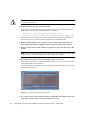
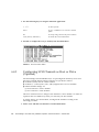
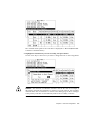
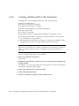
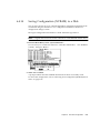
6. Type an ID number for that controller. Note – To create a total of 128 LUNs, you must have a minimum of four host IDs (two each for Channels 1 and 3) and might have a maximum of six host IDs (two each for Channels 1 and 2, and 3). Each host ID can have up to 32 partitions, which are then mapped to LUNs to create a total not to exceed 128. 7. From the Main Menu, select “System Functions,” then “Reset controller.” The configuration change takes effect only after the controller is reset. Chapter 6 First-Time Configuration 6-11 6.4.5 Enabling a Solaris Host to Recognize New Devices and LUNs You need to edit the sd.conf and /etc/system files for additional host LUN assignments. By default, a Solaris host is configured for one host LUN per SCSI target which is not enough LUNs for a Sun StorEdge 3310 SCSI array. 1. Edit the /kernel/drv/sd.conf file to add more targets and LUNs (up to 32 LUNs per logical drive, and a maximum of 128 LUNs per Sun StorEdge 3310 array). See the example file“Solaris sd.conf Setup and Volume Labels” on page E-1. 2. Add the following line to the /etc/system file if you have more than 8 LUNs (any LUNs in addition to LUNs 0 through 7): set scsi_options=0x43ff8 Note – Editing the /etc/system file is needed only for onboard host bus adapter connections. 3. Reboot the host to implement the file changes. Solaris 8 requires a reconfiguration reboot to create device files and implement sd.conf changes but you do not need a reconfiguration reboot for Solaris 9. reboot -- -r For Solaris 9, use the following commands to create device files after you have edited sd.conf and/or the /etc/system file. No reboot is necessary with this command: update_drv -f sd devfsadm 6-12 Sun StorEdge™ 3310 SCSI Array Installation, Operation, and Service Manual • October 2002 6.4.6 Reviewing Default Logical Drives and RAID Levels A logical drive is a set of drives grouped together to operate under a given RAID level. Each controller is capable of supporting as many as eight logical drives. The logical drives can have the same or different RAID levels. ■ A logical drive can be further divided into a maximum of 32 partitions. ■ The total number of partitions must not exceed 128 partitions per RAID array. To create a maximum of 128 partitions, refer to “Planning for 128 LUNs (Optional)” on page 6-26. For a 12-drive array, the RAID array is preconfigured as follows: ■ One RAID 5 logical drive, consisting of four physical drives ■ One RAID 5 logical drive, consisting of five physical drives ■ One global spare The following table highlights the RAID levels available. TABLE 6-2 RAID Level Definitions RAID Level Description RAID 0 Striping without data redundancy; provides maximum performance. RAID 1 Mirrored or duplexed disks; for each disk in the system, a duplicate disk is maintained for data redundancy. It requires 50% of total disk capacity for overhead. RAID 3 Striping with dedicated parity. Parity is dedicated to one drive. Data is divided into blocks and striped across the remaining drives. RAID 5 Striping with distributed parity; this is the best-suited RAID level for multitasking or transaction processing.The data and parity are striped across each drive in the logical drive, so that each drive contains a combination of data and parity blocks. NRAID NRAID stands for Non-RAID. The capacity of all the drives is combined to become one logical drive (no block striping). The capacity of the logical drive is the total capacity of the physical drives. NRAID does not provide data redundancy. For more information about logical drives, spares, and RAID levels, refer to Chapter 1, Basic Concepts, in the Sun StorEdge 3310 SCSI RAID Firmware Guide. Chapter 6 First-Time Configuration 6-13 6.4.7 Completing Basic Configuration ■ Optionally define any additional partitions for each logical drive. Refer to “Partitioning a Logical Drive (optional)” on page 6-22. ■ Optionally add host SCSI IDs and more logical drives to create 128 LUNs. Refer to: ■ ■ ■ ■ 6.4.8 “Planning for 128 LUNs (Optional)” on page 6-26, “Creating Additional Host IDs (Optional)” on page 6-10, “Creating Logical Drive(s) (optional)” on page 6-14. Map the logical drive(s) to the host LUNs (required). Refer to“Mapping Logical Drive Partitions to Host LUNs” on page 6-27. Creating Logical Drive(s) (optional) The RAID array is already configured with one or two RAID 5 logical drives and one global spare. Each logical drive consists of a single partition by default. This procedure is used to modify the RAID level and to add more logical drives, if necessary. In this procedure, you configure a logical drive to contain one or more hard drives based on the desired RAID level, and partition the logical drive into additional partitions. Note – If you want to assign 128 partitions to 128 LUNs in an array, you need to have a minimum of four logical drives (each with 32 partitions). For redundancy across separate channels, you can also create a logical drive containing drives distributed over separate channels. You can then partition the logical unit into one or several partitions. A logical drive consists of a group of SCSI drives. Each logical drive can be configured a different RAID level. A drive can be assigned as the local spare drive to one specified logical drive, or as a global spare drive that is available to all logical drives on the RAID array. Spares can be part of automatic array rebuild. A spare is not available for logical drives with no data redundancy (NRAID and RAID 0). 6-14 Sun StorEdge™ 3310 SCSI Array Installation, Operation, and Service Manual • October 2002 4 GB Drive Channel 0 2 GB 4 GB ID 0 ID 5 ID 2 ID 3 4 GB Drive Channel 1 2 GB 2 GB 4 GB ID 1 ID 6 2 GB ID 14 ID 0 Local Spare for LD1 Global Spare RAID 5 8GB Logical Drive 0 FIGURE 6-4 RAID 3 6GB Logical Drive 1 Example Allocation of Local and Spare Drives in Logical Configurations 1. View the connected drives. Before configuring disk drives into a logical drive, it is necessary to understand the status of physical drives in your enclosure. a. Use the arrow keys to scroll down to “view and edit Scsi drives” and press Return. Chapter 6 First-Time Configuration 6-15 This displays information of all the physical drives that are installed. b. Use the arrow keys to scroll through the table. Check that all installed drives are listed here. If a drive is installed but is not listed, it might be defective or might not be installed correctly, contact your RAID supplier. When the power is on, the controller scans all hard drives that are connected through the drive channels. If a hard drive was connected after the controller completed initialization, use the “Scan SCSI Drive” function to let the controller recognize the newly added hard drive and configure it as a member of a logical drive. Caution – Scanning an existing drive removes its assignment to any logical drive. All data on that drive is lost. 2. Create a logical drive. a. Scroll through the Main Menu and select “view and edit Logical drive.” 6-16 Sun StorEdge™ 3310 SCSI Array Installation, Operation, and Service Manual • October 2002 b. Select the first available unassigned logical drive (LG) and press Return to proceed. You can create as many as eight logical drives from drives on any SCSI bus. When prompted to “Create Logical Drive?” select Yes and press Return to proceed. A pull-down list of supported RAID levels is displayed. 3. Select a RAID level for this logical drive. RAID 5 is used in the following example screens. For brief descriptions of RAID levels, refer to “Reviewing Default Logical Drives and RAID Levels” on page 6-13. For more information about RAID levels, refer to Chapter 1 in the Sun StorEdge 3310 SCSI RAID Firmware User Guide. 4. Select your member drive(s) from the list of available physical drives. The drives can be tagged for inclusion by highlighting the drive and then pressing Return. An asterisk (*) mark is displayed on the selected physical drive(s). To deselect the drive, press Return again on the selected drive. The “*” mark disappears. Note – You must select at least the minimum number of drives required per RAID level. Each RAID level requires an even number of drives. a. Use the up and down arrow keys to select more drives. Chapter 6 First-Time Configuration 6-17 b. After all physical drives have been selected for the logical drive, press Esc key to continue to the next option. After member physical drives are selected, a list of selections is displayed. 5. Optionally set Maximum Physical Drive Capacity and assign spares. a. Optionally select “Maximum Drive Capacity” from the above menu, and press Return. Note – Changing the maximum drive capacity reduces the size of the logical drive and leave some disk space unused. As a rule, a logical drive should be composed of physical drives with the same capacity. A logical drive can only use the capacity of each drive up to the maximum capacity of the smallest drive. b. Optionally add a local spare drive from the list of unused physical drives. 6-18 Sun StorEdge™ 3310 SCSI Array Installation, Operation, and Service Manual • October 2002 Note – A global spare cannot be created while creating a logical drive. The spare chosen here is a local spare and automatically will replace any failed disk drive in this logical drive. The local spare is not available for any other logical drive. Note – A logical drive created in a RAID level which has no data redundancy (NRAID or RAID 0) does not support spare drive rebuilding. 6. Optionally select “Logical Drive Assignments” to assign this logical drive to the secondary controller. By default, all logical drives are automatically assigned to the primary controller. If you use two controllers for the redundant configuration, a logical drive can be assigned to either of the controllers to balance workload. Logical drive assignment can be changed any time later. Chapter 6 First-Time Configuration 6-19 a. Press Esc key or No to exit from this window without changing the controller assignment. b. Select “Yes,” press Return to confirm, and then press Esc key to continue when all the preferences have been set. A confirmation box is displayed on the screen. c. Verify all information in the box before choosing “Yes” to proceed. A message indicates that the logical drive initialization has begun. d. Press Esc key to cancel the “Notification” prompt. e. After the logical drive initialization is completed, use the Esc key to return to the Main Menu. 7. Select “view and edit Logical drives” to view details of the created logical drive. 6-20 Sun StorEdge™ 3310 SCSI Array Installation, Operation, and Service Manual • October 2002 6.4.9 Changing a Logical Drive Controller Assignment (Optional) By default, logical drives are automatically assigned to the primary controller. If you assign half the drives to the secondary controller, the maximum speed and performance is somewhat improved due to the redistribution of the traffic. To balance the workload between both controllers, you can distribute your logical drives between the primary controller (displayed as the Primary ID or PID) and the secondary controller (displayed as the Secondary ID or SID). After a logical drive has been created, it can be assigned to the secondary controller. Then the host computer associated with the logical drive can be mapped to the secondary controller (see “Mapping Logical Drive Partitions to Host LUNs” on page 6-27). 1. To change a logical drive controller assignment, select “view and edit Logical drives” from Main Menu, and press Return. 2. Select “logical drive assignments” and press Return. The reassignment is evident from the “view and edit Logical drives” screen. A “P” in front of the LG number means that the logical drive is assigned to the primary controller. An “S” in front of the LG number means that the logical drive is assigned to a secondary controller. For example, “S1” indicates that logical drive 1 assigned to the secondary controller. Chapter 6 First-Time Configuration 6-21 Note – The editable logical drive NAME name is used only in the RAID firmware administration and monitoring, and does not appear anywhere on the host. You can create a logical drive NAME after the logical drive is created: Select the logical drive in the above screen, and press Return. Then select “logical drive name,” type the desired name, and press Return. 3. Press Esc to return to the Main Menu. 4. Reset the controller to implement the change. Select “system Functions” on the Main Menu. Then select “Reset controller” and press Return. You must reset the controller for the changes to take effect. 6.4.10 Partitioning a Logical Drive (optional) You might divide a logical drive into several partitions, or use the entire logical drive as a single partition. You might configure up to 32 partitions for each logical drive. For guidelines on setting up 128 LUNs, refer to “Planning for 128 LUNs (Optional)” on page 6-26. Caution – If you modify the size of a partition or logical drive, you lose all data on those drives. 6-22 Sun StorEdge™ 3310 SCSI Array Installation, Operation, and Service Manual • October 2002 Partition 0 2GB Partition 1 1GB Partition 2 5GB RAID 5 (8 GB) Logical Drive 0 Partition 0 2.5GB RAID 3 (6 GB) Partition 1 1.5GB Logical Drive 1 Partition 2 FIGURE 6-5 2GB Partitions in Logical Configurations To partition a logical drive, perform the following steps. 1. From the Main Menu, select “view and edit Logical drives.” 2. Select the logical drive you want to partition, then press Return. 3. Select “Partition logical drive” from the menu, then press Return. Chapter 6 First-Time Configuration 6-23 4. Select from the list of undefined partitions and press Return. The following prompt then is displayed: “Partitioning the Logical Drive will make it no longer eligible for membership in a logical volume. Continue Partition Logical Drive?” 5. Select Yes. A list of the partitions for this logical drive will appear. If the logical drive has not yet been partitioned, all the logical drive capacity is listed as “partition 0.” 6. Press Return and type the desired size for the selected partition, and then press Return to proceed. A warning prompt is displayed: “This operation will result in the loss of all data on the partition! Partition Logical Drive?” 7. Select Yes. 8. Press Return to confirm. The remaining capacity of the logical drive is automatically allotted to the next partition. In the following figure, a partition size of 3000MB was entered; the remaining storage of 27000 MB is allocated to the partition below the partition created. 6-24 Sun StorEdge™ 3310 SCSI Array Installation, Operation, and Service Manual • October 2002 9. Repeat the preceding steps to partition the remaining capacity of your logical drive. You can create up to 32 partitions per logical drive, with a total number of partitions not to exceed 128 partitions/LUNs per the RAID array. Note – When you modify a partition or logical drive size, you must re-configure all host LUN mappings. All the host LUN mappings are removed with any change to partition capacity. See “Mapping Logical Drive Partitions to Host LUNs” on page 6-27. Note – When a partition of logical drive/logical volume is deleted, the capacity of the deleted partition is added to the partition above the deleted partition. Chapter 6 First-Time Configuration 6-25 6.4.11 Planning for 128 LUNs (Optional) If you want to create 128 LUNs which is the maximum number of storage partitions which can be mapped for a RAID array, set up one of the following configurations: ■ Create four host IDs. Create four logical drives. Partition each logical drive into 32 partitions (4 times 32 = 128). Map the 128 partitions to the four host IDs. This is the most commonly used configuration. or ■ Create six host IDs (this requires three host drives), perform one of the following steps, and then map the 128 partitions to the 6 host IDs. ■ ■ ■ Create 4 logical drives of 32 partitions each Create 5 logical drives with total number of partitions equaling 128 (four logical drives with 25 partitions each and one with 28 partitions) Create 6 logical drives (six logical drives with 21 partitions each and one with 23 partitions). For details on how to add host IDs, refer to “Creating Additional Host IDs (Optional)” on page 6-10. Note – For an overview of how partitions, LUNs, and host IDs work, refer to “Mapping Logical Drive Partitions to Host LUNs” on page 6-27. To set up 128 LUNs, the following steps are required. 1. Create a minimum of four host IDs. By default, you have two host IDs: Channel 1 ID 0 (primary controller) and Channel 3 ID 1 (secondary controller). You can have a total of two IDs per channel, one for the Primary Controller and one for the secondary controller. For the detailed procedure, refer to “Creating Additional Host IDs (Optional)” on page 6-10. 2. Confirm that the allowed number of LUNs per host id is 32. Go to “view and edit Configuration parameters,” and select “hostside SCSI Parameters.” If the “LUNs per Host SCSI ID” is not 32, highlight the line, press Return and select the number 32. 6-26 Sun StorEdge™ 3310 SCSI Array Installation, Operation, and Service Manual • October 2002 3. Create at least four logical drives. For the detailed procedure, refer to “Creating Logical Drive(s) (optional)” on page 6-14. 4. For each logical drive, create a number of partitions per logical drive until you reach a total of 128 partitions, then map those partitions to the host IDs. For the detailed procedures, refer to “Partitioning a Logical Drive (optional)” on page 6-22 and “Mapping Logical Drive Partitions to Host LUNs” on page 6-27. 6.4.12 Mapping Logical Drive Partitions to Host LUNs The next step is to map each storage partition as one system drive (host ID/LUN). The host SCSI adapter recognizes the system drives after re-initializing the host bus. A SCSI channel (SCSI bus) can connect up to 15 devices (excluding the controller itself) when the Wide function is enabled (16-bit SCSI). Each device has one unique ID. The figure below illustrates the idea of mapping a system drive to host ID/LUN combination. ■ The SCSI ID is like a cabinet, and the drawers are the LUNs (LUN is short for logical unit number). ■ Each cabinet (SCSI ID) can have up to 32 drawers (LUNs). ■ Data can be stored into one of the LUNs of the SCSI ID. Most SCSI host adapters treat a LUN like another SCSI device. ■ The maximum number of LUNs which can be created for a RAID array is 128. To create a total of 128 LUNs, refer to “Planning for 128 LUNs (Optional)” on page 6-26. Chapter 6 First-Time Configuration 6-27 LUN 0 LUN 1 LUN 2 Each SCSI ID/LUN looks like a storage device to the host computer. Channel 3 Channel 1 ID 1 ID 1 ID ID 0 0 Logical Drive 1 LUN 0 2.5GB LUN 1 1GB LUN 2 LUN 0 Partition 0 Logical Drive 0 5GB Logical Drive 0 LUN 1 Partition 1 1.5GB Partition 2 LUN 2 Logical Drive 0 2GB 6-28 Logical Drive 1 Partition 1 Logical Drive 1 2GB FIGURE 6-6 Partition 2 Mapping Partitions to Host ID/LUNs Sun StorEdge™ 3310 SCSI Array Installation, Operation, and Service Manual • October 2002 Partition 0 To map a logical drive partition to a LUN, perform the following steps. 1. On the Main Menu, select “view and edit Host luns.” 2. Select a specific host-channel ID and press Return. Select a logical drive if prompted. 3. Select a LUN number, and press Return. Select a logical drive, then highlight a partition, and press Return. 4. Select “Map Host LUN.” 5. Confirm the mapping scheme by selecting “Yes.” The same partition might be mapped to multiple LUNs on multiple host channels. This feature is necessary for clustered environments and redundant path environments. 6. Press Esc key to return to the Main Menu. Chapter 6 First-Time Configuration 6-29 7. Repeat the above procedure for each partition until all partitions are mapped to a LUN. 8. Select “system Functions” on the Main Menu, and select “Reset controller” to implement the new configuration settings. 9. To verify unique mapping of each LUN (unique LUN number, unique DRV number, or unique Partition number), select the “view and edit Host luns” command and press Return. 6.4.13 Create Device Files for Solaris Environment 1. Edit the /kernel/drv/sd.conf file to include the newly mapped LUNs which are available to the host. For details, refer to “Solaris sd.conf Setup and Volume Labels” on page E-1. 2. For Solaris 8 and higher, to create device files for the newly mapped LUNs on the host, type: /usr/sbin/devfsadm -v 3. The new LUNs are displayed when you use the Solaris format command. format 4. If the format command does not see the newly mapped LUNs, re-check the sd.conf file for accuracy and reboot the host: reboot -- -r 6-30 Sun StorEdge™ 3310 SCSI Array Installation, Operation, and Service Manual • October 2002 6.4.14 Saving Configuration (NVRAM) to a Disk You can select to back up your controller-dependent configuration information. We recommend using this function to save configuration information whenever a configuration change is made. The logical configuration information is stored within the logical drive. Note – A logical drive must exist for the controller to write NVRAM content onto it. 1. From the Main Menu, select “system Functions.” Use arrow keys to scroll down and select “controller maintenance,” “save NVRAM to disks,” then press Return. 2. Select Yes to confirm. A prompt confirms that the NVRAM information has been successfully saved. To restore the configuration, refer to “Restoring Your Configuration (NVRAM) From a File” on page 8-23. Chapter 6 First-Time Configuration 6-31 6.5 Installing Software The following software tools are available on the Sun StorEdge Professional Storage Manager CD-ROM, provided with your array: ■ Sun StorEdge 3310 SCSI Configuration Service, a management and monitoring program ■ Sun StorEdge 3310 SCSI Diagnostic Reporter software, a monitoring utility ■ Sun StorEdge 3310 SCSI CLI, a command line utility to download firmware and display the event log The Sun StorEdge 3310 SCSI Array Documentation CD-ROM provides the related user guides with detailed installation and configuration procedures for these tools. 6.5.1 Other Supported Software For other supported software, see the Sun StorEdge 3310 SCSI Array Release Notes. 6.5.2 Enabling VERITAS DMP To enable VERITAS Dynamic Multi-Pathing (DMP) support on VERITAS Volume Manager Version 3.2, perform the following steps. 1. Configure at least two SCSI channels as host channels (channels 1 and 3 by default) and add additional SCSI host IDs if needed. 2. Connect host cables to the I/O host ports in step 1. 3. Map each LUN to two host channels to provide dual-pathed LUNs. 4. Add the correct SCSI string to vxddladm so VxVM can manage the LUNs as a multi-pathed JBOD. # vxddladm addjbod vid=SUN pid="StorEdge 3310" # vxddladm listjbod VID PID Opcode Page Code Page Offset SNO length ================================================================ SEAGATE ALL PIDs 18 -1 36 12 SUN StorEdge 3310 18 -1 36 12 5. Reboot the hosts. System reboot is required to implement these changes. 6-32 Sun StorEdge™ 3310 SCSI Array Installation, Operation, and Service Manual • October 2002 CHAPTER 7 Checking LEDs This chapter describes the front- and rear-panel LEDs, which give the clear status of the operation of all drives and modules. Topics covered in this chapter are: ■ ■ ■ “LEDs When Array Is First Powered On” on page 7-1 “Front-Panel LEDs” on page 7-3 “Rear-Panel LEDs” on page 7-5 ■ ■ 7.1 “RAID Controller LEDs” on page 7-5 “Other Rear-Panel LEDs” on page 7-7 LEDs When Array Is First Powered On With the array powered up without the SCSI bus configuration cable installed while the array is not connected to a server, you should see the LED conditions described in TABLE 7-1 and TABLE 7-2. TABLE 7-1 Front-Panel LED Status When Array Is First Powered On Drive LEDs Solid green Chassis ear LEDs Solid green 7-1 TABLE 7-2 Rear-Panel LED Status When Array Is First Powered On I/O Module: ERROR LED Blinking green (no bus configuration; invalid state) TERM LED Solid green (autotermination enabled) SNGL LED Inactive (no bus configuration; invalid state) Controller Module: 7-2 ACTIVITY LED (Inactive (controller not busy) Center LED (status symbol) Slow blinking green: good primary controller Solid green: good secondary controller Right LED (battery symbol) Blinking green if battery is charging Solid green if battery is fully charged Ethernet port LEDs Inactive Power/fan module LEDs Solid green Event module LEDs Solid green Sun StorEdge™ 3310 SCSI Array Installation, Operation, and Service Manual • October 2002 7.2 Front-Panel LEDs The drive LEDs are located between the rows of drives on the front panel (see following figure). The system operation LEDs are located on the right ear of the chassis. Drive LED 1 LED 4 LED 2 LED 5 LED 3 LED 6 Drive LED 7 LED 10 LED 8 LED 11 LED 9 LED 12 Disk 1 Disk 4 Disk 7 Disk 10 Disk 2 Disk 5 Disk 8 Disk 11 Disk 3 Disk 6 Disk 9 Disk 12 FIGURE 7-1 POWER FAN TEMP EVENT RESET Push button Front Panel LEDs The following figure shows the front panel LEDs and reset pushbutton. POWER FAN TEMP EVENT RESET pushbutton FIGURE 7-2 Chassis Ear LEDs and Reset Button on Front Panel The following table lists the front-panel LEDs. Chapter 7 Checking LEDs 7-3 TABLE 7-3 Front Panel LEDs LED LED Color Description Drive Solid green Blinking green Solid yellow Good: Drive power-up and spin-up OK. Good: Drive activity. Failed: Drive failure. Solid green Solid yellow Power supply good. Failed: One or more output voltages out of range. Fan (Fan icon) Monitors the fan speed within nominal operational RPM specification of 5000 RPM. Solid green Solid yellow Good: Over 3150 RPM. Faulty: Failed: Under 3150 RPM. Temp (Thermometer icon) Monitors the temperature level and indicates violations of internal temperature thresholds of 55C and 60C. Solid green Solid yellow Blinking yellow Good: Under temperature threshold of 55C. Failed: Temperature threshold equal to or over 55C. Failed: Temperature threshold equal to or over 60C. Blinking frequency of 4 Hz +/– 1 Hz. Solid green Solid yellow Blinking Yellow Normal operation of RAID controller and EMUs. Abnormal event EMU. Abnormal event in RAID controller or failed RAID controller. Blinking frequency of 4 Hz +/–1 Hz. Power (Light bulb icon) Monitors the DC output voltage within tolerance specification. Overcurrent protection shutting down any voltage output displayed. Voltage thresholds: +5 VDC +/–.25 VDC +12 VDC +/–.6 VDC Current thresholds: +5 VDC 35A +12 VDC 25A Event (Caution icon) Indicates any abnormal or failure event in the RAID controller or EMU. 7-4 Sun StorEdge™ 3310 SCSI Array Installation, Operation, and Service Manual • October 2002 7.3 Rear-Panel LEDs The rear-panel LED colors indicate the conditions described in the following figures and tables. The following figure is the rear-panel with LEDs. I/O module PS ERROR PS TERM TERM CH 0 SB CH 3 SB SNGL BUS CONF SNGL CH 1 CH 2 DUAL BUS CONF DB POWER POWER + Activity COM <...> 10/100 BASE-T COM 10/100 BASE-T + Activity Power/fan module FIGURE 7-3 EMU E V E N T 1 EMU E V E N T 2 <...> Controller module Event module Rear-Panel LEDs If you see a blinking green or yellow LED, you can have an incorrect configuration or a failed component. 7.3.1 RAID Controller LEDs The following figure illustrates the RAID controller LEDs on the rear panel. + Activity COM FIGURE 7-4 <...> 10/100 BASE-T RAID Controller LEDs Chapter 7 Checking LEDs 7-5 The following table lists the RAID Controller LEDs. TABLE 7-4 RAID Controller LEDs LED Color Status Activity LED LED inactive Not active. Blinking green Controller is busy. Solid green Controller data is in cache. Solid yellow Power is lost and data is in memory. Center LED (status symbol) Slow-blinking green Solid green Solid yellow Good: primary controller. Good: secondary controller. Failed controller. Right LED (battery symbol) Blinking green Solid green Solid yellow Battery is charging. Battery is fully charged. Battery failed. Amber Blinking green Ethernet link is connected and working. Ethernet link is transmitting or receiving data. Ethernet 10/100 BASE-T LEDs (left and right corners of the connector) 7-6 Sun StorEdge™ 3310 SCSI Array Installation, Operation, and Service Manual • October 2002 7.3.2 Other Rear-Panel LEDs The following table lists the other rear-panel module LEDs. TABLE 7-5 Other Rear-Panel Module LEDs Module Power supply/fan Monitors the DC output voltage within tolerance specification. Overcurrent protection shutting down any voltage output will also be displayed. Voltage thresholds: +5 VDC +/–.25 VDC +12 VDC +/–.6 VDC Current Thresholds: +5 VDC 35A +12 VDC 25A EMU module I/O module TERM LEDs ERROR LED SNGL LED LED Color Status Solid green Solid yellow Solid green Solid yellow Power supply good. Failed: one or more output voltages out of range. Good fan: Over 3150 RPM. Faulty/failed: Under 3150 RPM. Solid green Solid yellow Good EMU module. Failed EMU module. Solid green Inactive LED Autotermination enabled. Autotermination disabled. Blinking green Solid yellow Inactive LED Invalid single- or dual-cable configuration. Failed I/O module. Valid single- or dual-bus configuration, and I/O module is good. Solid green Inactive LED Cabled for single-bus configuration. Cabled for dual-bus configuration. Chapter 7 Checking LEDs 7-7 The figure below illustrates the AC power supply and fan module. POWER FIGURE 7-5 AC Power Supply and Fan Module The figure below illustrates the DC power supply and fan module. POWER FIGURE 7-6 DC Power Supply and Fan Module The figure below illustrates the I/O Module for a RAID Array. ERROR TERM SNGL TERM CH 0 SB CH 1 FIGURE 7-7 7-8 CH 3 CH 2 SB SNGL BUS CONF DUAL BUS CONF DB I/O Module for a RAID Array Sun StorEdge™ 3310 SCSI Array Installation, Operation, and Service Manual • October 2002 The figure below illustrates the I/O Module for the Expansion Unit. ERROR TERM TERM B B FIGURE 7-8 SB SB A A I/O Module for an Expansion Unit The following figure illustrates the EMU module. EMU FIGURE 7-9 EMU Module Chapter 7 Checking LEDs 7-9 7-10 Sun StorEdge™ 3310 SCSI Array Installation, Operation, and Service Manual • October 2002 CHAPTER 8 Maintaining and Troubleshooting Your Array This chapter covers the following maintenance and troubleshooting topics: ■ “Problem In Seeing the Array on the Host” on page 8-2 ■ “RAID LUNs Not Visible to the Host” on page 8-2 ■ “JBOD Disks Not Visible to the Host” on page 8-3 ■ “Key Screens and Commands” on page 8-3 ■ “The Controller Firmware Initial Screen” on page 8-3 ■ “Main Menu” on page 8-4 ■ “Quick Installation” on page 8-5 ■ “Checking Status Windows” on page 8-5 ■ “Logical Drive Status Table” on page 8-5 ■ “Logical Volume Status Table” on page 8-7 ■ “SCSI Drive Status Table” on page 8-8 ■ “SCSI Channel Status Table” on page 8-10 ■ “Controller Voltage Temperature Status” on page 8-12 ■ “Viewing SAF-TE Status” on page 8-13 ■ “Viewing Event Logs on the Screen” on page 8-15 ■ “Controller Failure Symptoms, Logical Drive Rebuild, and Replacement” on page 8-16 ■ “General Controller Failure Response” on page 8-16 ■ “Automatic Logical Drive Rebuild” on page 8-17 ■ “Manual Rebuild” on page 8-17 ■ “Concurrent Rebuild in RAID (0+1)” on page 8-20 ■ “Identifying a Failed Drive for Replacement” on page 8-20 ■ “Restoring Your Configuration (NVRAM) From a File” on page 8-23 ■ “Fatal Drive Failure” on page 8-24 ■ “Upgrading Firmware” on page 8-25 ■ “Review Firmware Upgrade Features” on page 8-25 ■ “Downloading Firmware Upgrades” on page 8-26 8-1 To check front-panel and back-panel LEDs, see “Checking LEDs” on page 7-1. For more troubleshooting tips, refer to the Sun StorEdge 3310 SCSI Release Notes at: www.sun.com/products-n-solutions/ hardware/docs/Network_Storage_Solutions/Workgroup/3310 8.1 Problem In Seeing the Array on the Host 8.1.1 RAID LUNs Not Visible to the Host By default, all RAID arrays are preconfigured with one or two logical drives. For a logical drive to be visible to the host server, its partitions must be mapped to host LUNs. (For mapping details, refer to “Mapping Logical Drive Partitions to Host LUNs” on page 6-27.) Check that you have completed this task. To make the mapped LUNs visible to the host, perform the following steps for the Solaris host: 1. Ensure that the /kernel/drv/sd.conf file is correctly configured. See the example file“Solaris sd.conf Setup and Volume Labels” on page E-1. 2. Add the following line to the /etc/system file if you have more than 8 LUNs (any LUNs in addition to LUNs 0 through 7). This is required for many onboard host adapters. set scsi_options=0x43ff8 3. Run the devfsadm utility to rescan the newly mapped LUNs. 4. To implement all changes to the above files, reboot the host with the reboot --r command. The new LUNs are displayed when you perform the format command. 8-2 Sun StorEdge™ 3310 SCSI Array Installation, Operation, and Service Manual • October 2002 8.1.2 JBOD Disks Not Visible to the Host If you attach a JBOD array directly to a host server and do not see the drives on the host server, check that the cabling is correct and that there is proper termination. Refer to the special cabling procedures in “Cabling JBODs” on page B-1. If the cabling is correct and the drives are still not visible, run the devfsadm utility to rescan the drives. The new disks can be seen when you perform the format command. If the drives are still not visible, reboot the host(s) with the reboot -- -r command so that the drives are visible to the host. 8.2 Key Screens and Commands 8.2.1 The Controller Firmware Initial Screen You see the following initial controller screen when you first access the RAID controller firmware (via the controller COM port or Ethernet port). To complete the connection to your management console, select the VT100 terminal mode or the appropriate mode for your communications software, and press Return. Chapter 8 Maintaining and Troubleshooting Your Array 8-3 TABLE 8-1 Components of the Controller Firmware Window Component Description Cursor bar Move the cursor bar to a desired item, and then press Return to select. Controller name Identifies the type of controller. Transfer rate indicator Indicates the current data transfer rate. Gauge range Use + or – keys to change the gauge range in order to view the transfer rate indicator. Cache status Indicates the current cache status. PC Graphic (ANSI mode) Enters the Main Menu and operates in ANSI mode. (VT-100 mode) 8.2.2 Enters the Main Menu and operates in VT-100 mode. PC graphic (ANSI+color mode) Enters the Main Menu and operates in ANSI color mode. Show transfer rate+show cache status Press Return on this item to show the cache status and transfer rate. Main Menu After you have selected the mode and pressed Return on the initial screen, the Main Menu is displayed. Use the arrow keys to move the cursor bar through the menu items, then press Return to choose a menu, or press the ESC (Escape) key to return to the previous menu/screen. 8-4 Sun StorEdge™ 3310 SCSI Array Installation, Operation, and Service Manual • October 2002 8.2.3 Quick Installation RESERVED for special use. Caution – DO NOT USE this menu item unless directed by technical support. 8.3 Checking Status Windows 8.3.1 Logical Drive Status Table To check and configure logical drives, from the Main Menu select “view and edit Logical drives,” and press Return. The following screen displays the status of all logical drives. Chapter 8 Maintaining and Troubleshooting Your Array 8-5 TABLE 8-2 8-6 Parameters Displayed in the Logical Drive Status Window Parameter Description LG Logical drive number P0: Logical drive 0 of the primary controller where P = primary controller and 0 = logical drive number S1: Logical drive 1 of the secondary controller where s = secondary controller and 1 = logical drive number ID Logical drive ID number (controller-generated). LV The logical volume to which this logical drive belongs. NA indicated no logical volume. RAID RAID level SIZE (MB) Capacity of the logical drive in megabytes. Status Logical drive status. INITING The logical drive is now initializing. INVALID The logical drive was improperly created or modified. For example, the logical drive was created with “Optimization for Sequential I/O,” but the current setting is “Optimization for Random I/O.” GOOD The logical drive is in good condition. DRV FAILED A drive member failed in the logical drive. FATAL FAIL More than one drive member in a logical drive has failed. REBUILDING The logical drive is rebuilding. DRV ABSENT One of the disk drives cannot be detected. INCOMPLETE Two or more member disk drives in this logical drive have failed. O Indicates the performance optimization set when the logical drive was initialized. This cannot be changed after the logical drive is created. S Optimization for Sequential I/O R Optimization for Random I/O #LN Total number of drive members in this logical drive. Sun StorEdge™ 3310 SCSI Array Installation, Operation, and Service Manual • October 2002 TABLE 8-2 Parameters Displayed in the Logical Drive Status Window (Continued) Parameter Description #SB Number of standby drives available for the logical drive. This includes local spare and global spare disk drives available for the logical drive. #FL Number of failed disk drive member(s) in the logical drive. Name Logical drive name (user configurable) To handle failed, incomplete, or fatal fail status, see “General Controller Failure Response” on page 8-16 and “Fatal Drive Failure” on page 8-24. 8.3.2 Logical Volume Status Table To check status and to configure logical volumes, from the Main Menu select “view and edit logical volumes,” and press Return. The screen displays the status of all logical volumes. A logical volume may contain up to eight logical drives. Caution – This feature is not supported in the Configuration Service program. It is available but rarely used in the firmware. It has been replaced by the use of partitions in logical drives. Chapter 8 Maintaining and Troubleshooting Your Array 8-7 TABLE 8-3 Parameters Parameters Displayed in the Logical Volume Status Window Description Logical volume number where P = primary controller and S = secondary controller 8.3.3 ID Logical volume ID number (controller-generated) Size(MB) Capacity of the logical volume in megabytes #LD The number of logical drive(s) in this logical volume SCSI Drive Status Table To check and configure physical SCSI drives, from the Main Menu select “view and edit scsi Drives,” and press Return. The following screen displays the status of all SCSI drives. If there is a drive installed but not listed, the drive may be defective or not installed correctly. When power is on, the controller scans all hard drives that are connected through the drive channels. If a hard drive was connected after the controller completes initialization, use “Scan SCSI Drive” under the “view and edit scsi Drives” command to let the controller recognize the newly added hard drive and configure it as a member of a logical drive. 8-8 Sun StorEdge™ 3310 SCSI Array Installation, Operation, and Service Manual • October 2002 TABLE 8-4 Parameters Displayed in the Drive Status Window Parameters Description Slot Slot number of the SCSI drive Chl SCSI channel of the connected drive ID SCSI ID of the drive Size (MB) Drive capacity in megabytes Speed xxMB Maximum synchronous transfer rate of this drive. Async The drive is using asynchronous mode. LG_DRV x Status Vendor and Product ID The SCSI drive is a drive member of logical drive x. If Status shows “STAND-BY,” the SCSI drive is a local spare drive of logical drive x. GLOBAL The SCSI drive is a global spare drive. INITING The drive is initializing. ON-LINE The drive is in good condition. REBUILD The drive is rebuilding. STAND-BY Local spare drive or global spare drive. The local spare drive’s LG_DRV column shows the logical drive number. The global spare drive LG_DRV column shows “Global.” NEW DRV The new drive has not been configured to any logical drive or as a spare drive. USED DRV The drive was previously configured as a logical drive or as a spare drive but is not currently configured. BAD Failed drive. ABSENT Drive slot is not occupied. MISSING Drive once existed, but is now missing. SB-MISS Spare drive missing. Vendor and product model information of the drive. To handle BAD drives, refer to “General Controller Failure Response” on page 8-16. If two drives show BAD and MISSING status, see “Fatal Drive Failure” on page 8-24. Chapter 8 Maintaining and Troubleshooting Your Array 8-9 8.3.4 SCSI Channel Status Table To check and configure SCSI channels, from the Main Menu select “view and edit Scsi channels,” and press Return. The resulting screen displays the status of all SCSI channels for this controller. Caution – Do not change the PID and SID values of drive channels. A mapped host channel sometimes shows the current sync clock as “Async/Narrow” and correctly identify the change in speed. The host adapter driver is designed to downgrade the negotiation rate on certain errors (predominantly parity errors). There is little or no performance change. TABLE 8-5 Parameters Description Chl SCSI channel’s ID. Mode Channel mode. PID 8-10 Parameters Displayed in the SCSI Channel Window RCCom Redundant controller communication channel Host The channel is functioning as a host channel. Drive The channel is functioning as a drive channel. Primary controller’s SCSI ID mapping: * Multiple SCSI IDs were applied (host channel mode only). x The SCSI ID for host LUNs mapped to this channel in Host Channel mode. SCSI ID for the primary controller in drive channel mode. NA No SCSI ID applied. Sun StorEdge™ 3310 SCSI Array Installation, Operation, and Service Manual • October 2002 TABLE 8-5 Parameters Displayed in the SCSI Channel Window (Continued) Parameters Description SID Secondary controller’s SCSI ID mapping: DefSynClk DefWid S Term CurSynClk CurWid * Multiple SCSI IDs (Host Channel mode only). x The SCSI ID for host LUNs mapped to this channel in host channel mode. SCSI ID for the secondary controller in drive channel mode. NA No SCSI ID applied Default SCSI bus synchronous clock: xx.xMHz Maximum synchronous transfer rate set to xx.x. Async Channel is set for asynchronous transfers. Default SCSI bus width: Wide Channel is set to allow wide (16-bit) transfers. Narrow Channel is set to allow narrow (8-bit) transfers. Signal: S Single-ended L LVD F Fibre Terminator status: On Termination is enabled. Off Termination is disabled. NA For a redundant controller communications channel (RCCOM). Current SCSI bus synchronous clock: xx.xMHz The current speed at which the channel is communicating. Async. The channel is communicating asynchronously or not device is detected. (empty) The default SCSI bus synchronous clock has changed. Reset the controller for changes to take effect. Current SCSI bus width: Wide The channel is currently servicing wide 16-bit transfers. Narrow The channel is currently servicing wide 8-bit transfers. (empty) The default SCSI bus width has changed. Reset the controller for the changes to take effect. Chapter 8 Maintaining and Troubleshooting Your Array 8-11 8.3.5 Controller Voltage Temperature Status To check the status of controller voltage and temperature, perform the following steps. 1. From the Main Menu select “view and edit Peripheral devices,” and press Return. 2. Select “Controller Peripheral Device Configuration,” and press Return. 3. Select “View Peripheral Device Status” and press Return to view voltage and temperature status of the RAID unit. The components checked for voltage and temperature are displayed on the screen and are defined as normal or out-of-order. 8-12 Sun StorEdge™ 3310 SCSI Array Installation, Operation, and Service Manual • October 2002 8.3.6 Viewing SAF-TE Status The SAF-TE controller is located on the SCSI I/O module. To check the status of SAF-TE components (temperature sensors, cooling fans, the beeper speaker, power supplies, and slot status), perform the following steps. 1. From the Main Menu select “view and edit Peripheral devices,” and press Return. 2. Select “View Peripheral Device Status,” and press Return. 3. Select “SAF-TE Device,” and press Return to view the status of temperature sensors, power supplies, beeper speaker, and cooling fans. The temperature sensor displays the current temperature of each sensor in degrees Fahrenheit. The drive slot status indicates that a slot is filled by displaying a SCSI ID number: ■ Single bus configuration: 0 through 13 ID numbers if all 12 drives are filled. SCSI IDs 6 and 7 are reserved for host communication. If there is an empty slot, the message “No Device Inserted” is displayed. See FIGURE 8-1. ■ Dual-bus configuration (not supported): the message “No Device Inserted” for the six drives on one channel and six ID numbers for the second channel. See FIGURE 8-2. Chapter 8 Maintaining and Troubleshooting Your Array 8-13 FIGURE 8-1 Example of SAF-TE Device Status Window in a Single Bus Configuration In a dual bus configuration example, the below SAF-TE window displays “No Device Inserted” for six drives which are actually inserted into slots. The SAF-TE protocol does not support a dual-bus configuration and only recognizes one bus (half the drives) if you have a dual-bus configuration. FIGURE 8-2 Example of SAF-TE Device Status Window in a Dual Bus Configuration 4. To check that you have all slots filled in a dual bus configuration, see “SCSI Drive Status Table” on page 8-8 and check the column labeled “Chl ID.” 8-14 Sun StorEdge™ 3310 SCSI Array Installation, Operation, and Service Manual • October 2002 8.3.7 Viewing Event Logs on the Screen A controller event log records an event or alarm which occurs after the system is powered on. Note – The Event Monitoring Units in each RAID unit and each Expansion Unit send messages to the controller log which report problems and status of the fans, temperature, and voltage. Caution – Powering off or resetting the controller automatically deletes all recorded event logs. To view the event logs on screen, select “view and edit Event logs” on the Main Menu and press Return. The controller can store up to 1000 event logs. An event log can record a configuration or operation event as well as an error message or alarm event. TABLE 8-6 Example Event Logs [0181] Controller Initialization Completed [2181] LG:0 Logical Drive NOTICE: Starting Initialization [2182] Initialization of Logical Drive 0 Completed [2181] LG:1 Logical Drive NOTICE: Starting Initialization [2182] Initialization of Logical Drive 2 Completed To clear the saved event logs, scroll the cursor down to the last event and press Return. A prompt “Clear Above xx Event Logs?” is displayed. Select Yes to clear the recorded event logs. Chapter 8 Maintaining and Troubleshooting Your Array 8-15 8.4 Controller Failure Symptoms, Logical Drive Rebuild, and Replacement Controller failure symptoms are as follows: ■ The surviving controller sounds an audible alarm. ■ The center LED (status symbol) flashes yellow on the failed controller. ■ The surviving controller sends event messages announcing the controller failure of the other controller. A warning message, “SCSI Bus Reset Issued” is displayed for each of the SCSI channels. In addition, an alert message says “Redundant Controller Failure Detected.” 8.4.1 General Controller Failure Response If one controller in the redundant controller configuration fails, the surviving controller temporarily takes over for the failed controller until it is replaced. A failed controller is managed by the surviving controller which disables and disconnects from its counterpart while gaining access to all the signal paths. The surviving controller then manages the ensuing event notifications and takes over all processes. It is always the primary controller regardless of its original status, and any replacement controller afterward assumes the role of the secondary controller. The failover and failback processes are completely transparent to the host. Controllers are hot-swappable, and replacing a failed unit takes only a few minutes. To maintain your redundant controller configuration, replace the failed controller as soon as possible. For details, see “Replacing a Controller Module” on page 9-4. 8-16 Sun StorEdge™ 3310 SCSI Array Installation, Operation, and Service Manual • October 2002 8.4.2 Automatic Logical Drive Rebuild Rebuild with Spare: When a member drive in a logical drive fails, the controller first examines whether there is a local spare drive assigned to this logical drive. If yes, it automatically starts to rebuild the data of the failed disk to it. If there is no local spare available, the controller searches for a global spare. If there is a global spare, it automatically uses it to rebuild the logical drive. Failed Drive Swap Detect: If neither a local spare drive nor a global spare drive is available, and the “Periodic Auto-Detect Failure Drive Swap Check Time” is “disabled,” the controller does not attempt to rebuild unless you apply a forcedmanual rebuild. To enable this feature, go to the Main Menu choose “view and edit Configuration parameters,” then select “Drive-side SCSI Parameters,” and select “Periodic AutoDetect Failure Drive Swap Check Time.” When the “Periodic Auto-Detect Failure Drive Swap Check Time” is “Enabled” (that is, a check time interval has been selected), the controller detects whether or not the failed drive has been swapped (by checking the failed drive's channel/ID). Once the failed drive has been swapped, the rebuild begins immediately. If the failed drive is not swapped but a local spare is added to the logical drive, the rebuild begins with the spare. For a flowchart of automatic rebuild, see FIGURE 8-3. 8.4.3 Manual Rebuild When a user applies forced-manual rebuild, the controller first examines whether there is any local spare assigned to the logical drive. If yes, it automatically starts to rebuild. If there is no local spare available, the controller will search for a global spare. If there is a global spare, the logical drive rebuild will begin. See FIGURE 8-4. If neither local spare nor global spare is available, the controller will examine the SCSI channel and ID of the failed drive. After the failed drive has been replaced by a healthy one, the logical drive rebuild begins on the new drive. If there is no drive available for rebuilding, the controller will not attempt to rebuild until the user applies another forced-manual rebuild. Chapter 8 Maintaining and Troubleshooting Your Array 8-17 FIGURE 8-3 8-18 Automatic Rebuild Sun StorEdge™ 3310 SCSI Array Installation, Operation, and Service Manual • October 2002 FIGURE 8-4 Manual Rebuild Chapter 8 Maintaining and Troubleshooting Your Array 8-19 8.4.4 Concurrent Rebuild in RAID (0+1) RAID (0+1) allows multiple-drive failure and concurrent multiple-drive rebuild. Drives newly swapped must be scanned and set as local spares. These drives will be rebuilt at the same time; you do not need to repeat the rebuilding process for each drive. 8.4.5 Identifying a Failed Drive for Replacement If there is a failed drive in the RAID 5 logical drive, replace the failed drive with a new drive to keep the logical drive working. Caution – If, when trying to remove a failed drive, you mistakenly remove the wrong drive, you will no longer be able to access the logical drive because you have incorrectly failed another drive. Note – The following procedure only works if there is no I/O activity. To find a failed drive, identify a single drive, or test all drive activity LEDs, perform the following steps. 1. On the Main Menu, select “view and edit scsi Drives” and press Return. Select the drive you want to identify, and then press Return. 2. Select the “Identifying scsi drive” function. Select “flash All drives” to flash the activity LEDs of all of the drives in the drive channel, and press Return. FIGURE 8-5 8-20 Identify Drive Option with Flashing LEDs on Drives Sun StorEdge™ 3310 SCSI Array Installation, Operation, and Service Manual • October 2002 The option to change the Flash Drive Time is displayed. The read/write LED of a failed hard drive will not light. This LED will prevent you from removing the wrong drive and is also helpful in locating a drive. 3. Confirm your choice by pressing Return and selecting “Yes.” Alternatively, to flash the read/write LED of only a selected drive, choose “flash Selected drive” or “flash all But selected drive” and perform the same procedure. FIGURE 8-6 Selecting a Command to Flash All or Selected Drive LEDs Flashing Selected SCSI Drive The read/write LED of the drive you select lights steadily for a configurable period of time from 1 to 999 seconds. LED steadily on Disk 1 Disk 4 Disk 7 Disk 10 Disk 2 Disk 5 Disk 8 Disk 11 Disk 3 Disk 6 Disk 9 Disk 12 FIGURE 8-7 Flashing the Drive LED of a Selected Drive Chapter 8 Maintaining and Troubleshooting Your Array 8-21 Flashing All SCSI Drives The “Flash All SCSI Drives” function lights LEDs of all good drives except the defective one. Disk 1 Disk 4 Disk 7 Disk 10 Disk 2 Disk 5 Disk 8 Disk 11 Disk 3 Disk 6 Disk 9 Disk 12 FIGURE 8-8 Flashing All Drive LEDs to Detect a Defective Non-Flashing Drive Flashing All But Selected Drives With this command, except for the selected drive, the read/write LEDs of all connected drives will light for a configurable period of time from 1 to 999 seconds. LED is not lit Disk 1 Disk 4 Disk 7 Disk 10 Disk 2 Disk 5 Disk 8 Disk 11 Disk 3 Disk 6 Disk 9 Disk 12 FIGURE 8-9 8-22 Flashing All Drive LEDs Except a Selected Drive LED Sun StorEdge™ 3310 SCSI Array Installation, Operation, and Service Manual • October 2002 8.4.6 Restoring Your Configuration (NVRAM) From a File If you have saved a configuration file and want to apply the same configuration to another array or reapply it to the array that had the configuration originally, you must be certain that the channels and SCSI IDs in the configuration file are correct for the array where you are restoring the configuration. The NVRAM configuration file will restore all configuration settings (channel settings, host IDs, etc.) but does not rebuild logical drives. To save a configuration file, see “Saving Configuration (NVRAM) to a Disk” on page 6-31. Caution – If the channels or SCIS IDs are not a correct match for the array, you will lose access to the mismatched channels or drives when you restore the configuration with the configuration file. Note – In the Configuration Service program, you can save a configuration file that can restore all configurations and rebuild all logical drives. However, it will also erase all data when it rebuilds all logical drives, so operation is performed only when no data has been stored or all data has been transferred to another array. To restore configuration settings from a saved NVRAM file, perform the following steps. 1. From the Main Menu choose “system Functions.” 2. Select “Controller maintenance” and press Return. 3. Select “Restore NVRAM from disks,” and press Return. 4. Press Yes to confirm. A prompt will notify you that the controller NVRAM data has been successfully restored from disks. Chapter 8 Maintaining and Troubleshooting Your Array 8-23 8.4.7 Fatal Drive Failure With the redundant RAID array system, your system is protected with the RAID parity drive and by the default global spare (you may have more than one). Note – A FATAL FAIL status occurs when there is one more drive failing than the number of spare drives available for the logical drive. If a logical drive has two global spares available, then three failed drives must occur for FATAL FAIL status. In an extremely rare occurrence where two or more drives appear to fail at the same time, perform the following steps. 1. Discontinue all input/output activity immediately. 2. To cancel the beeping alarm, use a paperclip to press the Reset button (below the LEDs on the front-right ear of the array). 3. Physically check that all the drives are firmly seated in the array and that none have been partially or completely removed. 4. Check again the firmware Main Menu and check the “view and edit Logical drives,” and look for: Status: FAILED DRV (one failed drive) or Status: FATAL FAIL (two or more failed drives) 5. Highlight the logical drive, press Return, and select “view scsi drives.” If two physical drives have a problem, one drive will have a BAD status and one drive will have a MISSING. The MISSING status is a reminder that one of the drives may be a “false” failure. The status does not tell you which drive might be a false failure. 6. Do one of the following: ■ Choose “system Functions” from the Main Menu and press Return. Select “Reset controller,” and press Return. or ■ 8-24 Power off the array. Wait five seconds, and power on the array. Sun StorEdge™ 3310 SCSI Array Installation, Operation, and Service Manual • October 2002 7. Repeat steps 4 and 5 to check the logical and SCSI drive status. After resetting the controller, if there is a false bad drive, the array will automatically start rebuilding the failed RAID set. If the array does not automatically start rebuilding the RAID set, check the status under “view and edit Logical drives.” ■ If the status is “FAILED DRV,” manually rebuild the RAID set (refer to “Manual Rebuild” on page 8-17). ■ If the status is still “FATAL FAIL,” you have lost all data on the logical drive and must re-create the logical drive. Proceed with the following procedures: ■ ■ ■ “Replacing a Drive” on page 9-3 for the failed drive “Deleting a Logical Drive” (Section 3.7 in the Sun StorEdge 3310 SCSI RAID Firmware User Guide) “Creating Logical Drive(s) (optional)” on page 6-14 For additional troubleshooting tips, refer to the Sun StorEdge 3310 SCSI Array Release Notes located at: www.sun.com/products-n-solutions/ hardware/docs/Network_Storage_Solutions/Workgroup/3310 8.5 Upgrading Firmware 8.5.1 Review Firmware Upgrade Features The following firmware upgrade features apply to the controller firmware: ■ Redundant Controller Rolling Firmware Upgrade When download is performed on a dual-controller system, firmware is flashed onto both controllers without interrupting host I/Os. When the download process is complete, the primary controller will reset and let the secondary controller take over the service temporarily. When the primary controller comes back on-line, the secondary controller will hand over the workload and then reset itself for the new firmware to take effect. The rolling upgrade is automatically performed by controller firmware, and the user's intervention is not necessary. Chapter 8 Maintaining and Troubleshooting Your Array 8-25 ■ Automatically Synchronized Controller Firmware Versions A controller that replaces a failed unit in a dual-controller system is often running a newer release of firmware version. To maintain compatibility, the surviving primary controller will automatically update the firmware running on the replacement secondary controller to the firmware version of the primary controller. ■ Upgrading Firmware Using the Serial Port Connections (from Windows hosts) The firmware can be downloaded to the RAID controller by using an ANSI/VT100 compatible emulation program. The emulation program must support the ZMODEM file transfer protocol. Emulation programs such as HyperTerminal, Telix, and PROCOMM Plus can perform the firmware upgrade. 8.5.2 Downloading Firmware Upgrades For a fast and easy download of new versions of controller firmware, disk drive firmware, and SAF-TE firmware, use one of the following tools: ■ ■ ■ Sun StorEdge 3310 CLI (with an in-band SCSI connection, for Solaris and Windows hosts) Sun StorEdge 3310 Configuration Service program (with an in-band SCSI connection, for Solaris and Windows hosts) Firmware application (for controller firmware download only from a Windows host with an out-of-band serial port connection) Note – To download firmware to disk drives or SAF-TE firmware to a JBOD directly attached to a host, you must use the Sun StorEdge 3310 SCSI Configuration Service program. Caution – You should not use both in-band and out-of-band connections at the same time to manage the array or you might cause conflicts between multiple operations. 8-26 Sun StorEdge™ 3310 SCSI Array Installation, Operation, and Service Manual • October 2002 Controller Firmware Upgrade from Firmware Application You can also use a Windows terminal emulation session with ZMODEM capabilities to access the firmware application. To upgrade the RAID controller firmware through the serial port and the firmware application, perform the following steps. 1. Establish the serial port connection. ■ To upgrade both the boot record and the firmware binary, perform step 2. ■ To upgrade only the firmware binary, perform step 3. 2. Upgrade both boot record and firmware binaries with the following steps. a. From the Main Menu scroll down to “System Functions.” b. Go to “Controller Maintenance” and select “Advanced Maintenance.” c. Select “Download Boot Record and Firmware.” d. Set ZMODEM as the file transfer protocol of your emulation software. e. Send the Boot Record Binary to the controller: In HyperTerminal, go to the “Transfer” menu and choose “Send file.” If you are not using HyperTerminal, choose “Upload” or “Send” (depending on the software). f. After the Boot Record has been downloaded, send the Firmware Binary to the controller: In HyperTerminal, go to the “Transfer” menu and choose “Send file.” If you are not using HyperTerminal, choose “Upload” or “Send” (depending on the software). When the Firmware completes downloading, the controller will automatically reset itself. 3. Upgrade the firmware binary only with the following steps. a. From the Main Menu scroll down to “System Functions.” b. Go to “Controller Maintenance” and select “Advanced Maintenance.” c. Choose “Download Firmware.” d. Set ZMODEM as the file transfer protocol of your emulation software. e. Send the Firmware Binary to the controller: In HyperTerminal, select “Send file.” If you are not using Hyper, choose “Upload” or “Send” (depending on the software). When the Firmware completes downloading, the controller will automatically reset itself. Chapter 8 Maintaining and Troubleshooting Your Array 8-27 8-28 Sun StorEdge™ 3310 SCSI Array Installation, Operation, and Service Manual • October 2002 CHAPTER 9 Installing Spares and FRUs This chapter provides information on installing spares and FRUs. Topics covered in this chapter are: ■ ■ ■ ■ ■ ■ ■ ■ “Static Electricity Precautions” on page 9-2 “Replacing a Drive” on page 9-3 “Replacing a Controller Module” on page 9-4 “Replacing I/O Modules” on page 9-6 “Replacing a Power/Fan Module” on page 9-7 “Replacing the Terminator Module” on page 9-8 “Replacing the EMU Module” on page 9-10 “Replacing the Battery” on page 9-11 All FRUs are hot-swappable except the I/O module, which is hot-serviceable. Hotserviceable means that the module can be replaced while the array and hosts are powered up but the connected hosts must be inactive. The following table lists the FRUs that are currently available. For additional FRUs, consult your sales representative or the web site. TABLE 9-1 Currently Available FRUs FRU Model Number Description F370-5394-01 Event monitoring unit F370-5396-01 I/O module, LVD, expansion unit or JBOD F370-5397-01 I/O module, LVD, RAID F370-5403-01 Controller module, 512 memory, battery, 2U LVD F370-5399-01 Terminator module F370-5422-01 Drive module, 36GB LVD, 10K RPM F370-5398-01AC AC power and fan module, 2U F370-5527-01DC DC power and fan module, 2U 9-1 TABLE 9-1 Currently Available FRUs (Continued) F370-5533-01 Battery, LVD F370-5405-01 Cable, LVD, 1-foot, jumper F370-5528-01 Cable, LVD, 1.5-foot, expansion F370-5393-01 Box, 2U, JBOD, LVD F370-5524-01 Box, 2U, RAID, LVD XTA-3310-DC-KIT Power and fan module, 2U, DC XTA-3310-RK-19M** Kit, rackmount, 2U, 19-in. wide, 18- to 28-in. deep XTA-3310-RK-19L** Kit, rackmount, 2U, 19-in. wide, 28- to 36-in. deep XTA-3310-RK-19C** Kit, Telco rackmount center mount, 2U, 19-in wide XTA-3310-RK-19F** Kit, Telco rackmount flush mount, 2U, 19-in wide **See “Rackmounting” on page 4-1 for installation instructions. 9.1 Static Electricity Precautions Follow these steps to prevent damaging the FRUs: 9-2 ■ Remove plastic, vinyl, and foam from the work area. ■ Before handling a FRU, discharge any static electricity by touching a ground surface. ■ Wear an antistatic wrist strip. ■ Do not remove a FRU from its antistatic protective bag until you are ready to install it. ■ When removing a FRU from the array, immediately place it in an antistatic bag and in antistatic packaging. ■ Handle a FRU only by its edges, and avoid touching the circuitry. ■ Do not slide a FRU over any surface. ■ Limit body movement (which builds up static electricity) during FRU installation. Sun StorEdge™ 3310 SCSI Array Installation, Operation, and Service Manual • October 2002 9.2 Replacing a Drive The drive module is hot-swappable; it is replaced while the array is powered on. Thumbscrew Drive handle Handle pin Chassis notch FIGURE 9-1 The Side View of A Drive Module Pulled Out of the Chassis To Remove the Disk Drive 1. Unlock the lock with the provided key, and gently pull the plastic front bezel off the front of the unit. 2. Turn the thumbscrew counterclockwise two or three times until the drive module is loosened. 3. Gently pull the release handle upward, and pull the drive module out of the array. To Insert the Disk Drive 1. Slide the drive module into the drive slot and push it until the handle pins are inserted into the chassis notch. 2. Lower the disk drive handle so that the handle pin lines up with the chassis slot. 3. Pull down the drive handle and screw the thumbscrew clockwise until the thumbscrew is finger-tight. Chapter 9 Installing Spares and FRUs 9-3 9.3 Replacing a Controller Module Be sure to follow “Static Electricity Precautions” on page 9-2. Caution – If you power off the array and replace a controller, the replacement controller could become the primary controller and overwrite any configuration settings previously set. Before replacing a RAID controller, save the configuration settings to NVRAM. If power is removed before you replace a RAID controller, the settings can be restored from NVRAM. The replacement procedures for the RAID controller follow. To Save the Configuration Settings to NVRAM 1. From the firmware application Main Menu, choose “system Functions.” 2. Use the arrow keys to scroll down, and select “controller maintenance,” then select “save NVRAM to disks” and press Return. 3. Choose Yes to confirm. A prompt will inform you that NVRAM information has been successfully saved. To Remove a Controller Module 1. Keep the array powered on. 2. Turn the thumbscrews on the left and right sides of the controller module counterclockwise until the thumbscrews are disengaged from the chassis. 3. Hold the thumbscrews, and pull out the controller module. To Insert a Controller Module 1. Keep the array powered on. Gently slide the controller module into the unit until it clicks and is seated in the backplane. Caution – Be sure that the controller module is properly inserted into the guide rails. 2. Turn the thumbscrews on the left and right side of the controller module clockwise until finger-tight, to secure the module and to make the module’s frontpanel flush with the chassis. The new controller will automatically become the secondary controller. 9-4 Sun StorEdge™ 3310 SCSI Array Installation, Operation, and Service Manual • October 2002 3. If the array was powered off during the controller replacement, restore configuration settings from NVRAM if the new controller replaced an old controller: a. From the firmware application Main Menu, choose “system Functions.” Select “Controller maintenance” and press Return. b. Select “Restore NVRAM from disks” and press Return. Press Yes to confirm. c. A prompt will notify you that the controller NVRAM data has been successfully restored from disks. If Powered Off During Replacement or a Single-Controller Array Replacement If the array was powered off during the controller replacement or if you replaced a controller in a single-controller configuration, perform the following important steps. 1. Restore configuration settings from NVRAM if the new controller replaced an old controller: a. On the firmware main menu, select “system Functions,” select “Controller maintenance,” and press Return. b. Select “Restore NVRAM from disks” and press Return. Press Yes to confirm. 2. Set the parameter called the "Controller Unique Identifier" to the correct value: a. On the firmware main menu, select “view and edit Configuration parameters,” then select “Controller Parameters,” and press Return. b. From the Controller Parameters menu, select “Controller Unique Identifier <hex>” and press Return. Type in the value 0 (to automatically read the chassis serial number from the midplane) or type the hex value for the original serial number of the chassis (used when the midplane has been replaced). The Controller Unique Identifier is used to create Ethernet Addresses and World Wide Names. The value 0 is immediately replaced with the hex value of the chassis serial number. A non-zero value should only be specified if the chassis has been replaced but the original chassis serial number must be retained; this feature is especially important in a Sun Cluster environment to maintain the same disk device names in a cluster. 3. To implement the revised configuration settings from step 1 or 2, select “system Functions” on the Main Menu, select “Reset controller” and press Return. Chapter 9 Installing Spares and FRUs 9-5 9.4 Replacing I/O Modules FIGURE 9-2 The I/O Module Partially Pulled out of the Chassis Be sure to follow “Static Electricity Precautions” on page 9-2. The I/O module is hotserviceable. Hot-serviceable means that the module can be replaced while the array and hosts are powered up but the connected hosts must be inactive. As a best practice, power off the array. Caution – Connected hosts must be inactive during this replacement procedure. To Remove an I/O Module 1. Power off the array. 2. Turn the thumbscrews on the left and right sides of an I/O module counterclockwise until the thumbscrews are disengaged from the chassis. 3. Hold the thumbscrews and pull out the I/O module. 9-6 Sun StorEdge™ 3310 SCSI Array Installation, Operation, and Service Manual • October 2002 To Insert an I/O Module 1. Power off the array. 2. Slide the I/O module into the chassis until the module is firmly seated in the backplane, and the module’s front-panel is flush with the chassis. Caution – Be sure that the I/O module is properly inserted into the guide rails. 3. Turn the thumbscrews on the left and right sides of the I/O module clockwise until the thumbscrews are finger-tight, to secure the module. 9.5 Replacing a Power/Fan Module To Remove a Fan/Power Supply Module 1. Be sure to follow “Static Electricity Precautions” on page 9-2. Turn off the power and remove the power cable. 2. Turn the thumbscrew at the top of the power supply latch counterclockwise until the thumbscrew is disengaged from the power supply. Thumbscrew Latch Handle FIGURE 9-3 The Power Supply Partially Pulled out of the Chassis 3. Pull the latch forward about 45 degrees to disconnect the power supply/fan module from the midplane. 4. Use the power supply handle to pull the power supply/fan module out of the chassis. Chapter 9 Installing Spares and FRUs 9-7 To Insert a Fan/Power Supply Module 1. Slide the new module into the fan and power supply slot. 2. Push the latch back so that the power supply is fully inserted into the chassis. 3. Turn the thumbscrew at the top of the power supply latch clockwise until it is finger-tight, to secure the module. 4. Attach the power cable and turn the power back on. 9.6 Replacing the Terminator Module Be sure to follow “Static Electricity Precautions” on page 9-2. The terminator module is a thin module located between and behind the two controller modules. FIGURE 9-4 The Terminator Module Partially Pulled Out of the Chassis To Remove a Terminator Module 1. Power off the array. 2. Remove both controller modules: a. Turn the thumbscrews on the left and right sides of each controller module counterclockwise until the thumbscrews are disengaged from the chassis. b. Hold the thumbscrews and pull out the controller module. 3. Hold the terminator module by the front edges, and pull it out of the chassis. 9-8 Sun StorEdge™ 3310 SCSI Array Installation, Operation, and Service Manual • October 2002 To Insert a Terminator Module 1. Keep the power turned off. 2. Slide the terminator module into the chassis until it clicks and is seated in the backplane. Caution – Be sure that the terminator module is properly inserted into the guide rails. 3. Reinstall both controller modules: a. Gently slide each controller module into the unit until it is seated in the backplane. b. Turn the thumbscrews on the left and right side of the controller module clockwise until finger-tight, to secure the module. 4. Power on the array. Chapter 9 Installing Spares and FRUs 9-9 9.7 Replacing the EMU Module Be sure to follow “Static Electricity Precautions” on page 9-2. The EMU module is hot-swappable and can be replaced with the array powered on. FIGURE 9-5 The EMU Module Partially Pulled out of the Chassis To Remove an EMU Module 1. Turn the thumbscrews on the top and bottom of an EMU module counterclockwise until the thumbscrews are disengaged from the chassis. 2. Hold the thumbscrews, and pull out the EMU module. To Insert an EMU Module 1. Slide the new EMU module into the chassis until it is firmly seated in the backplane, and the module’s front panel is flush with the chassis. Caution – Be sure that the EMU module is properly inserted into the guide rails. 2. Turn the thumbscrews on the top and bottom of the EMU module clockwise until they are finger-tight, to secure the module. 9-10 Sun StorEdge™ 3310 SCSI Array Installation, Operation, and Service Manual • October 2002 9.8 Replacing the Battery The following steps are guidelines for replacing a battery on a RAID controller module. A battery is located on each controller module. To view the battery expiration date, pull out each controller module and look at the date specified. Battery FIGURE 9-6 Connector The Battery and Connector Follow these steps to replace a battery. 1. Remove the connector. FIGURE 9-7 The Connector Unplugged Chapter 9 Installing Spares and FRUs 9-11 2. Remove the screws. FIGURE 9-8 The Underside of the Controller Module With Screws Being Removed 3. Lift out the battery. FIGURE 9-9 9-12 The Top Side of the Controller Module With the Battery Being Lifted Out and Connector Unplugged Sun StorEdge™ 3310 SCSI Array Installation, Operation, and Service Manual • October 2002 4. Insert the new battery and attach the battery connector to the controller module. FIGURE 9-10 The Top and Side View of the Controller Module With the Battery Being Inserted Chapter 9 Installing Spares and FRUs 9-13 9-14 Sun StorEdge™ 3310 SCSI Array Installation, Operation, and Service Manual • October 2002 APPENDIX A SCSI Array Specifications This appendix provides the specifications for the Sun StorEdge 3310 SCSI array. The topics covered are: ■ “Summary of Sun StorEdge 3310 SCSI Array Specifications” on page A-2 ■ “Agency Approvals and Standards” on page A-3 A-1 A.1 Summary of Sun StorEdge 3310 SCSI Array Specifications Feature Description General • • • • Density • Up to 432GB in a RAID array • 21 in. chassis depth • RAID supports one expansion chassis in a dual-host configuration, or two expansion chassis in a single-host configuration Reliability • • • • • Redundant hot swappable FRUs Single or redundant active/active hot-swappable RAID controllers Redundant hot swappable event monitoring units (EMU) N+1 hot swappable power and cooling NEBS Level 3 and HALT test certified; Designed to meet 99.999% reliability RAID System Storage Resource Management • • • • • • • • • • Web-based 10/100BASE-T Ethernet support Serial port out-of-band support with modem control RAID Levels 0, 1, 0+1, 3, 5, 3+1, 5+1 Rolling firmware upgrades (with redundant RAID controllers) Up to 128 LUNs SNMP traps and MIB in firmware 512MB cache memory standard Four Ultra160 SCSI channels User-configurable as drive or host Support for Sun StorEdge 3310 SCSI Configuration Service and Diagnostic Reporter management software A-2 12 hot-pluggable drives in a 2U (3.5” high) chassis Ultra 160 SCSI buses Autosensing AC or DC power supplies Dual-host access in certain configurations Sun StorEdge™ 3310 SCSI Array Installation, Operation, and Service Manual • October 2002 A.2 Agency Approvals and Standards Product Safety Country Standard U.S. UL Listed to UL60950:2000, 3rd Edition Canada CSA Standard CAN/CSA-C22.2 No. 60950-00 3rd Edition Germany TÜV European Union EN60950:2000 Japan Part of World-wide CB Scheme Australia Part of World-wide CB Scheme Argentina Resolution 92-98 (S-Mark) Germany GS mark (ergonomics) (Rheinland) Russia Part of World-wide CB Scheme (GOST-R mark) Russia Hygienic Mark-(ergonomics) Electromagnetic Compatibility Country Standard U.S. FCC #47, Part 15, Subpart B, Class B Canada ICES-003 Japan VCCI Class B European Union EN 55022:1998 Class B Australia/New Zealand AS/NZS 3548:1996 Taiwan BSMI CNS 13438 Class B Russia GOST-R mark Germany Same as European Union Argentina S mark Appendix A SCSI Array Specifications A-3 Electromagnetic Interference Test Standard Harmonics Emissions EN 61000-3-2:2000 (No Limits) Voltage Flicker EN 61000-3-3:1995/A1:2001 (No Limits) ESD EN 55024 (8kV Contact, 15kV Air) RF Field EN 55024 (10V/m) Electrical Fast Transient Burst EN 55024 (1kV I/O, 2kV Power) Surge EN 55024 (1kV I/O, 1kV Power L-L, 2kV Power L-G) RF Conducted EN 55024 (3V I/O and Power) Power Frequency Magnetic Field EN 55024 (N/A monitors only) Voltage Dip and Interruption EN 55024 (0V/0.5cycle, 70%V/0.5sec, 0V/5sec) A-4 Sun StorEdge™ 3310 SCSI Array Installation, Operation, and Service Manual • October 2002 APPENDIX B Cabling JBODs You can connect a Sun StorEdge 3310 JBOD (Just a Bunch of Disks, no controller) array directly to a host server. This appendix covers the following topics: ■ ■ ■ “A Single Bus JBOD with One Host Connection” on page B-2 “A Single Bus JBOD with Two Host Connections” on page B-3 “Dual Bus JBOD Configurations” on page B-4 ■ “Dual Bus, Single Initiator Mode” on page B-5 ■ “Dual Bus, Multi-Initiator Mode” on page B-6 Caution – SCSI cables are not hot-swappable; that is, you should not connect or disconnect SCSI cables when the array is powered on. Caution – SCSI IDs are set based on the cabling on the array when it is powered up. If switching from single bus mode to dual bus mode or vice versa, the SCSI IDs will change after you power off, change the cabling, and then power on. Caution – If you change SCSI IDs on the array, ensure that your application points to the correct IDs. Caution – The I/O module is hot-serviceable which means that you can replace it or change its cables while the array is powered on but the SCSI host buses connected to the array must be inactive. B-1 B.1 A Single Bus JBOD with One Host Connection To connect a JBOD in a single bus configuration to a single host, connect the following ports: ■ Connect the bottom left input port to the top right port of the JBOD with the SCSI jumper cable. ■ Connect the bottom right input port to one host with a SCSI cable. Caution – BEFORE you disconnect a cable from the array, the host bus on that cable must be inactive. Caution – SCSI IDs are set based on the cabling on the array when it is powered up. If switching from single bus mode to dual bus mode or vice versa, the SCSI IDs will change after you power off, change the cabling, and then power on. Caution – If you change SCSI IDs on the array, ensure that your application points to the correct IDs. Host Connection FIGURE B-1 B-2 A Single Bus JBOD with One Host Connection (Rear View) Sun StorEdge™ 3310 SCSI Array Installation, Operation, and Service Manual • October 2002 The following table shows the default SCSI IDs for a 12-drive JBOD when you set up single bus configuration. TABLE B-1 B.2 SCSI Drive IDs for a JBOD in a Single Bus Configuration (Front View) ID 0 ID 3 ID 8 ID 11 ID 1 ID 4 ID 9 ID 12 ID 2 ID 5 ID 10 ID 13 A Single Bus JBOD with Two Host Connections To connect a JBOD in a single bus configuration to two hosts, connect the following ports: ■ ■ Connect the two bottom JBOD input ports with the SCSI jumper cable. Connect each top JBOD output port to a host server with a SCSI cable. Caution – BEFORE you disconnect a cable from the array, the host bus on that cable must be inactive. Caution – SCSI IDs are set based on the cabling on the array when it is powered up. If switching from single bus mode to dual bus mode or vice versa, the SCSI IDs will change after you power off, change the cabling, and then power on. Caution – If you change SCSI IDs on the array, ensure that your application points to the correct IDs. Appendix B Cabling JBODs B-3 Connections Host Host FIGURE B-2 A Single Bus JBOD with Two Host Connections (Rear View) The following table shows the default SCSI IDs for a 12-drive JBOD when you set up a single bus configuration. The SCSI IDs are 0 - 13, with IDs 6 and 7 reserved for host HBA connections. TABLE B-2 B.3 SCSI Drive IDs for a JBOD in a Single Bus Configuration (Front View) ID 0 ID 3 ID 8 ID 11 ID 1 ID 4 ID 9 ID 12 ID 2 ID 5 ID 10 ID 13 Dual Bus JBOD Configurations There are two important features to note with the dual bus JBOD configuration: B-4 ■ The bottom input ports on the JBOD must be terminated with an HBA host connection or with an external terminator. The upper I/O SCSI connectors are auto-terminated. ■ In a dual bus configuration, the SCSI ID numbers automatically change according to the cabling. Sun StorEdge™ 3310 SCSI Array Installation, Operation, and Service Manual • October 2002 B.3.1 Dual Bus, Single Initiator Mode Single initiator mode is when there is only one host connection on a SCSI channel. Multi-initiator mode is when there are two or more host connections on a SCSI channel. FIGURE B-3 shows a dual bus JBOD with two host connections, one host connection to each channel (single initiator mode). This is an efficient way to provide mirroring capability for a single host. Connections Host FIGURE B-3 Host Dual Bus, Single-Initiator JBOD Configuration Dual bus, single initiator mode: SCSI IDs are 8 to 13 on each channel. In the following table, A and B indicate the two different channel numbers assigned by the host, in the dual channel configuration. TABLE B-3 SCSI Drive IDs for a Dual Bus JBOD in Single Initiator Mode Channel A ID 8 Channel A ID 11 Channel B ID 8 Channel B ID 11 Channel A ID 9 Channel A ID 12 Channel B ID 9 Channel B ID 12 Channel A ID 10 Channel A ID 13 Channel B ID 10 Channel B ID 13 Appendix B Cabling JBODs B-5 B.3.2 Dual Bus, Multi-Initiator Mode FIGURE B-4 shows a multi-initiator, dual bus configuration where each host is connected to each host channel. This configuration is common for failover protection in a network cluster environment. FIGURE B-4 Dual Host, Dual Bus, Multi-Initiator JBOD Configuration Dual bus, multi-initiator mode: SCSI IDs are 0 to 5 on each channel. TABLE B-4 B-6 SCSI Drive IDs for a Dual Bus JBOD in Multi-Initiator Mode Channel A ID 0 Channel A ID 3 Channel B ID 0 Channel B ID 3 Channel A ID 1 Channel A ID 4 Channel B ID 1 Channel B ID 4 Channel A ID 2 Channel A ID 5 Channel B ID 2 Channel B ID 5 Sun StorEdge™ 3310 SCSI Array Installation, Operation, and Service Manual • October 2002 To Connect a Dual Bus JBOD to Two Hosts 1. Connect each JBOD port to a host as shown in FIGURE B-4. 2. Make inactive the host bus connections of any cable which will be installed or removed. Caution – The bottom input ports of the JBOD must have a host connection or external terminator to maintain SCSI bus integrity. Caution – BEFORE you disconnect a cable from the array, the host bus on that cable must be inactive. Caution – SCSI IDs are set based on the cabling on the array when it is powered up. If switching from single bus mode to dual bus mode or vice versa, the SCSI IDs will change after you power off, change the cabling, and then power on. Caution – If you change SCSI IDs on the array, ensure that your application points to the correct IDs. Note – The Sun SCSI LVD/MSE external terminator is part number XTA-3310-SCTERM (595-6750-01). Appendix B Cabling JBODs B-7 B-8 Sun StorEdge™ 3310 SCSI Array Installation, Operation, and Service Manual • October 2002 APPENDIX C Ethernet Connection This appendix provides Ethernet connection information. Topics covered are: C.1 ■ “Setting an IP Address” on page C-1 ■ “Setting Up Out-of-Band Management Over Ethernet” on page C-3 Setting an IP Address To set the IP address of the RAID controller, perform the following steps. 1. Access the Sun StorEdge RAID controller via a RAID Array COM port. 2. On the Main Menu, select “view and edit Configuration parameters.” 3. Select “Communication Parameters”, and then select “Internet Protocol (TCP/IP).” 4. Press Return on the chip hardware address, and then select “Set IP Address.” 5. Type the desired IP address, netmask, and Gateway values. C-1 FIGURE C-1 Setting the Controller IP Address 6. Reset the controller for the configuration to take effect; select “system Functions” from the Main Menu, then select “Reset controller” and press Return. Select Yes and press Return. FIGURE C-2 Resetting the Controller The controller will take a few minutes to format a small storage sector on each physical drive before logical drives can be successfully initialized. C-2 Sun StorEdge™ 3310 SCSI Array Installation, Operation, and Service Manual • October 2002 C.2 Setting Up Out-of-Band Management Over Ethernet 1. To access the RAID Array over an Ethernet connection, first set the IP address of the RAID Array by using the RAID Array COM port and the RAID firmware (refer to “Setting an IP Address” on page C-1). 2. Then connect the RAID Array Ethernet port to the network. 3. To connect to the firmware application program (used in this manual) from the host server, tenet directly to the IP address of the RAID array controller with the following command: # telnet <IP address> Press Cntrl-l (letter el) to refresh the screen and view the Main Menu. Note – If you reset the controller during a telnet session, you will be disconnected from the RAID array and will need to telnet back into the array. 4. To connect the Configuration Service program (on a host server) to a RAID array which has an IP address, refer to the out-of-band management instructions in the Sun StorEdge 3310 Configuration Service User Guide. In the following network illustration, there are two servers which receive Configuration Service Alert messages, and a Configuration Service management console which monitors and configures the RAID array as needed. Appendix C Ethernet Connection C-3 205.222.233.241 205.222.233.242 Server 205.222.233.243 Server Management Console Backbone RAID Array 205.222.233.250 PS ERROR PS TERM TERM CH 0 SB CH 3 SB SNGL BUS CONF SNGL CH 1 CH 2 DUAL BUS CONF DB POWER POWER + Activity <...> COM 10/100 BASE-T COM 10/100 BASE-T + Activity FIGURE C-3 C-4 EMU E V E N T 1 EMU E V E N T 2 <...> RAID Array 10/100BASE-T Ethernet Port Connected Directly to a Network Sun StorEdge™ 3310 SCSI Array Installation, Operation, and Service Manual • October 2002 APPENDIX D Record of Settings This appendix provides tables for recording configuration data. Topics covered are: ■ “View and Edit Logical Drives” on page D-2 ■ “Logical Drive Information” on page D-2 ■ “Logical Drive Partition Information” on page D-3 ■ “View and Edit Host LUNs” on page D-4 ■ “LUN Mappings” on page D-4 ■ “View and Edit SCSI Drives” on page D-5 ■ “View and Edit SCSI Channels” on page D-6 ■ “View and Edit Peripheral Devices” on page D-8 ■ “Save NVRAM to Disk, Restore from Disk” on page D-8 In addition to saving the configuration data in NVRAM to disk, keeping a hard copy of the controller configuration is also recommended. This will speed the recreation of the RAID in the event of a disaster. The following tables are provided as a model for recording configuration data. As a general rule, the configuration data in the NVRAM should be saved to disk or file whenever a configuration change is made. D-1 D.1 View and Edit Logical Drives D.1.1 Logical Drive Information LG D-2 ID LV RAID Level Size (MB) Status O #LN #SB #FL Sun StorEdge™ 3310 SCSI Array Installation, Operation, and Service Manual • October 2002 Name Disk Reserved Space D.1.2 LG Logical Drive Partition Information Partition Size (MB) LG Partition Size (MB) Appendix D Record of Settings D-3 D.2 View and Edit Host LUNs D.2.1 LUN Mappings Host Channel D-4 Pri. / Sec. Controller SCSI ID LUN Logical Drive / Logical Volume Partition Sun StorEdge™ 3310 SCSI Array Installation, Operation, and Service Manual • October 2002 Size D.3 Slot View and Edit SCSI Drives Chl ID Size (MB) Speed LG DRV? Global Spare? Local Spare? Appendix D Vendor and Product ID Record of Settings D-5 D.4 View and Edit SCSI Channels Slot Chl Chl D-6 ID Size (MB) Mode (Host / Drive) Speed LG DRV? Global Spare? Local Spare? Primary Controller SCSI ID(s) Vendor and Product ID Secondary Controller SCSI ID(s) Sun StorEdge™ 3310 SCSI Array Installation, Operation, and Service Manual • October 2002 Appendix D Record of Settings D-7 D.5 View and Edit Peripheral Devices View System Information Firmware Version Bootrecord Version Serial Number D.6 Update Firmware D-8 Save NVRAM to Disk, Restore from Disk Date Save NVRAM to Disk or File Date/Location Restore NVRAM from Disk Sun StorEdge™ 3310 SCSI Array Installation, Operation, and Service Manual • October 2002 Date APPENDIX E Solaris sd.conf Setup and Volume Labels This appendix provides an example sd.conf file that specifies available host LUN assignments. By default, a Solaris host has only one host LUN per target ID, which typically is not enough LUNs for a Sun StorEdge array. For your convenience, the procedure on how to label a Solaris volume is also provided. E.1 Editing the sd.conf File Edit the /kernel/drv/sd.conf file to add additional targets and LUNs, up to 128 LUNs which can be used in a single Sun StorEdge array. Then reboot the host. You may want to allow a few extra LUNs for flexibility over the coming months, but generally most administrators minimize the number of unused LUNs because each LUN causes a seven-second delay when you reboot the host. Note – The maximum number of LUNs per target is 32. Caution – After you edit sd.conf, you must reboot the host to enable the new LUN assignments. E-1 The following example file sets up targets 1 and 3 with a total of 41 LUNs (LUNs 0 through 31 on target 0, and LUNs 0 through 8 on target 3). Default LUNs listed first, followed by new LUNs. # Copyright (c) 1992, by Sun Microsystems, Inc. # #ident"@(#)sd.conf1.998/01/11 SMI" name="sd" class="scsi" class_prop="atapi" target=0 lun=0; . . name="sd" class="scsi" target=15 lun=0; #NEW LUNs have been appended to the default settings in the file, starting here. name="sd" class="scsi" target=1 lun=1; name="sd" class="scsi" target=1 lun=2; name="sd" class="scsi" target=1 lun=3; name="sd" class="scsi" target=1 lun=4; name="sd" class="scsi" target=1 lun=5; name="sd" class="scsi" target=1 lun=6; name="sd" class="scsi" target=1 lun=7; . . . name="sd" class="scsi" target=1 lun=31; E-2 Sun StorEdge™ 3310 SCSI Array Installation, Operation, and Service Manual • October 2002 name="sd" class="scsi" target=3 lun=1; name="sd" class="scsi" target=3 lun=2; name="sd" class="scsi" target=3 lun=3; name="sd" class="scsi" target=3 lun=4; name="sd" class="scsi" target=3 lun=5; name="sd" class="scsi" target=3 lun=6; name="sd" class="scsi" target=3 lun=7; name="sd" class="scsi" target=3 lun=8; # END additional lun entries E.2 Labeling a Volume For the Solaris operating environment to recognize a volume, it must be labeled with the format command. Whenever you create a volume, label it using the following procedure. For more information on the format command, see the format(1M) man page. To label a volume, perform the following steps. Appendix E Solaris sd.conf Setup and Volume Labels E-3 1. On the data host, type format at the root prompt. Specify the disk number when prompted. In this example, the array is shown as disk number 2. It can be identified by the SUN-3310-0200 label. format Searching for disks...done AVAILABLE DISK SELECTIONS: 0. c0t2d0 <SUN-3310-0200 cyl 34901 alt 2 hd 128 sec 256> disk8 /pci@70,2000/pci@2/SUNW,qlc@4/fp@0,0/ssd@w50020f230000b230,0 1. c0t2d1 <SUN-3310-0200 cyl 34901 alt 2 hd 128 sec 256> disk9 /pci@70,2000/pci@2/SUNW,qlc@4/fp@0,0/ssd@w50020f230000b230,1 2. c0t4d0 <SUN-3310-0200 cyl 34901 alt 2 hd 128 sec 256> disk10 /pci@70,2000/pci@2/SUNW,qlc@4/fp@0,0/ssd@w50020f230000b37f,0 3. c0t4d1 <SUN-3310-0200 cyl 34901 alt 2 hd 128 sec 256> disk11 /pci@70,2000/pci@2/SUNW,qlc@4/fp@0,0/ssd@w50020f230000b37f,1 4. c0t6d0 <SUN-3310-0200 cyl 34901 alt 2 hd 128 sec 256> disk12 /pci@70,2000/pci@2/SUNW,qlc@4/fp@0,0/ssd@w50020f230000b28e,0 5. c0t6d1 <SUN-3310-0200 cyl 34901 alt 2 hd 128 sec 256> disk13 /pci@70,2000/pci@2/SUNW,qlc@4/fp@0,0/ssd@w50020f230000b28e,1 6. c0t8d0 <SUN-3310-0200 cyl 34901 alt 2 hd 128 sec 256> disk14 /pci@70,2000/pci@2/SUNW,qlc@4/fp@0,0/ssd@w50020f230000b719,0 7. c0t8d1 <SUN-3310-0200 cyl 34901 alt 2 hd 128 sec 256> disk15 /pci@70,2000/pci@2/SUNW,qlc@4/fp@0,0/ssd@w50020f230000b719,1 8. c1t1d0 <SUN-3310-0200 cyl 34901 alt 2 hd 128 sec 256> disk8 /pci@71,2000/pci@2/SUNW,qlc@4/fp@0,0/ssd@w50020f230000af55,0 9. c1t1d1 <SUN-3310-0200 cyl 34901 alt 2 hd 128 sec 256> disk9 /pci@71,2000/pci@2/SUNW,qlc@4/fp@0,0/ssd@w50020f230000af55,1 10. c1t3d0 <SUN-3310-0200 cyl 34901 alt 2 hd 128 sec 256> disk10 /pci@71,2000/pci@2/SUNW,qlc@4/fp@0,0/ssd@w50020f230000afdf,0 11. c1t3d1 <SUN-3310-0200 cyl 34901 alt 2 hd 128 sec 256> disk11 /pci@71,2000/pci@2/SUNW,qlc@4/fp@0,0/ssd@w50020f230000afdf,1 12. c1t5d0 <SUN-3310-0200 cyl 34901 alt 2 hd 128 sec 256> disk12 /pci@71,2000/pci@2/SUNW,qlc@4/fp@0,0/ssd@w50020f230000b723,0 14. c3t2d0 <SUN18G cyl 7506 alt 2 hd 19 sec 248> /sbus@7d,0/SUNW,fas@1,8800000/sd@2,0 15. c3t3d0 <SUN18G cyl 7506 alt 2 hd 19 sec 248> /sbus@7d,0/SUNW,fas@1,8800000/sd@3,0 Specify disk (enter its number): 2 selecting c0t4d0 [disk formatted] ■ E-4 If the volume had been labeled previously using the format command, the next display is the FORMAT MENU. If the FORMAT MENU is displayed, continue to the next step. Sun StorEdge™ 3310 SCSI Array Installation, Operation, and Service Manual • October 2002 ■ If the volume had not been labeled previously using the format command, you will be prompted with the question: Disk not labeled. Label it now? If so, answer y at the prompt and press Return. The FORMAT MENU is displayed. 2. Type type to select a drive type. FORMAT MENU: disk type partition current format repair label analyze defect backup verify save inquiry volname !<cmd> quit format> type - select a disk select (define) a disk type select (define) a partition table describe the current disk format and analyze the disk repair a defective sector write label to the disk surface analysis defect list management search for backup labels read and display labels save new disk/partition definitions show vendor, product and revision set 8-character volume name execute <cmd>, then return0 Appendix E Solaris sd.conf Setup and Volume Labels E-5 3. Type 0 to choose the Auto configure option. Select the Auto configure option regardless of which drive types are displayed by the type option. For further information on partitioning, see the Solaris format(1M) man page. AVAILABLE DRIVE TYPES: 0. Auto configure 1. Quantum ProDrive 80S 2. Quantum ProDrive 105S 3. CDC Wren IV 94171-344 4. SUN0104 5. SUN0207 6. SUN0327 7. SUN0340 8. SUN0424 9. SUN0535 10. SUN0669 11. SUN1.0G 12. SUN1.05 13. SUN1.3G 14. SUN2.1G 15. SUN2.9G 16. SUN-3310-0100 17. other Specify disk type (enter its number)[16]: 0 c1t1d0: configured with capacity of 33.34GB <SUN-3310-0200 cyl 34145 alt 2 hd 16 sec 128> selecting c1t1d0 [disk formatted] 4. Type label and answer y when prompted to continue. format> label Ready to label disk, continue? y E-6 Sun StorEdge™ 3310 SCSI Array Installation, Operation, and Service Manual • October 2002 APPENDIX F Cable Pinouts This appendix identifies the pinouts for each connector used in the Sun StorEdge 3310 SCSI Array. Topics covered are: F.1 ■ “SCSI (Host or Drive) Connector” on page F-1 ■ “RJ-45 Connector” on page F-3 ■ “DB9 COM port” on page F-4 SCSI (Host or Drive) Connector Standard.8mm 68-pin LVD SCSI connector: FIGURE F-1 68-Conductor SCSI Pinout for LVD/MSE SCSI F-1 TABLE F-1 SCSI Connector Pin Numbers and Cable Pairs PIN# CABLE PAIR SE/LVD 1 2 3 4 5 6 7 8 9 10 11 12 13 14 15 16 17 18 19 20 21 22 23 24 25 26 27 28 29 30 31 32 33 34 30SR/+DB12 31SR/+DB13 32SR/+DB14 33SR/+DB15 34SR/+DBP1 16SR/+DB0 17SR/+DB1 18SR/+DB2 19SR/+DB3 20SR/+DB4 21SR/+DB5 22SR/+DB6 23SR/+DB7 24SR/+P_CRCA 25GND/GND 15DIFFSENSE 14TPWR/TPWR 13TPWR/TPWR 12RSVD/RSVD 5GND/GND 6SR/+ATN 7GND/GND 4SR/+BSY 3SR/+ACK 8SR/+RST 9SR/+MSG 10SR/+SEL 2SR/+C/D 1SR/+REQ 11SR/+I/0 26SR/+DB8 27SR/+DB9 28SR/+DB10 29SR/+DB11 PIN# CABLE SE/LVD PAIR 35 36 37 38 39 40 41 42 43 44 45 46 47 48 49 50 51 52 53 54 55 56 57 58 59 60 61 62 63 64 65 66 67 68 30-DB12/-DB12 31-DB13/-DB13 32-DB14/-DB14 33-DB15/-DB15 34-DBP1/-DBP1 16-DB0/-DB0 17-DB1/-DB1 18-DB2/-DB2 19-DB3/-DB3 20-DB4/-DB4 21-DB5/-DB5 22-DB6/-DB6 23-DB7/-DB7 24-DBP/-P_CRCA 25GND/GND 15GND/GND 14TPWR/TPWR 13TPWR/TPWR 12RSVD/RSVD 5GND/GND 6-ATN/-ATN 7GND/GND 4-BSY/-BSY 3-ACK/-ACK 8-RST/-RST 9-MSG/-MSG 10-SEL/-SEL 2-C/D/-C/D 1-REQ/-REQ 11-I/O/-I/O 26-DB8/-DB8 27-DB9/-DB9 28-DB10/-DB10 29-DB11/-DB11 *SR=Signal Return, *RSVD=Reserved, *GND=Ground, *TPWR=TERMPWR F-2 Sun StorEdge™ 3310 SCSI Array Installation, Operation, and Service Manual • October 2002 F.2 RJ-45 Connector FIGURE F-2 Ethernet RJ-45 Socket 10Base-T TABLE F-2 Ethernet RJ-45 Pin Description Pin No. Description. Color 1 TX + White with orange 2 TX – Orange 3 RX + White with green 4 Blue 5 White with blue 6 RX – Green 7 White with brown 8 Brown Appendix F Cable Pinouts F-3 F.3 DB9 COM port The COM port is a female DB9 connector that requires a male DB9 null modem cable. B9 (EIA/TIA 574) F-4 Vi FIGURE F-3 RS-232 DB9 (EIA/TIA 574) View of the Male End TABLE F-3 Pin Names Pin No. Name Notes/Description 1 DCD Data Carrier Detect 2 RD Receive Data (a.k.a. RxD, Rx) 3 TD Transmit Data (a.k.a. TxD, Tx) 4 DTR Data Terminal Ready 5 SGND Ground 6 DSR Data Set Ready 7 RTS Request To Send 8 CTS Clear To Send 9 RI Ring Indicator Sun StorEdge™ 3310 SCSI Array Installation, Operation, and Service Manual • October 2002 Index SYMBOLS #FL, 8–6 #LN, 8–6 #SB, 8–6 A active-active configuration, 6–2 active-standby configuration, 6–2 activity LED, 7–2, 7–6 automatic rebuild, 8–17 B BAD drive status, 8–9 battery LED, 7–2, 7–6 battery support, 6–3 baud rate, 6–6 bus configurations, 5–5 C cables standard package, 3–4 cabling cables supplied, 3–3 customer-provided, 3–4 drive IDs label summary, 5–7 dual bus configuration procedures, 5–11 dual bus drive IDs, 5–13 Ethernet connection, 5–18 Expansion Units, 5–16 limited number of drive IDs, 5–7 picture of connections, 5–2 procedures, 5–1, E–1 RS-232 connection, 5–18 single bus cabling procedures, 5–8 single bus drive IDs, 5–10 single vs dual bus configurations, 5–5 summary, 5–1 cache status, 8–4 channels set as host or drive, 6–9 clearances to allow, 2–5 comments sending to manufacturer, 1–xiii concurrent rebuild, 8–20 configuration first-time minimum, 6–4 key steps, 6–4 minimum requirements, 6–14 serial port connection, 6–5 controller assignment, 6–21 controller failure, 8–16 controller IDs, 6–10 controller limitations, 6–2 controller NAME, 6–22 controller voltage and temperature, 8–12 create logical drive, 6–16 customer obligations, 2–2 Index-1 disks not visible, 8–2 documentation how book is organized, 1–ix using UNIX commands, 1–x documentation available, 1–xi documentation comments, 1–xii documentation online, 1–xii drive channel defaults, 6–8 drive ID limitation, 5–7 drive status, 8–8 DRV FAILED status, 8–6 dual bus configuration procedures, 5–11 dual bus configurations, 5–5 dual bus drive IDs, 5–13 SCSI channel status, 8–10 SCSI drive status, 8–8 transfer rate indicator, 8–3 view event logs, 8–15 VT-100 screen selection, 8–3 VT100 terminal mode, 8–3 flash all but selected drive command, 8–21 Flash All Drives command, 8–20 flash drive time command, 8–21 flash selected drive command, 8–21 flashing all SCSI drives, 8–22 selected SCSI drives, 8–21 format utility, E–4 FRUs, installing, 9–1 E G electrical specifications, 2–4 electromagnetic compatibility (EMC), 2–3 EMU LED, 7–7 environmental range, 2–3 Ethernet connection, 5–18, C–3 event LED, 7–4 Event Logs, 8–15 Expansion Unit cabling, 5–16 gauge range, 8–4 D F fan LED, 7–4 fault-tolerance, 8–16 firmware automatic rebuild, 8–18 cache status, 8–3 controller failure/rebuild/replacement, 8–16 controller firmware upgrade, 8–25 controller voltage and temperature, 8–12 cursor bar, 8–3 gauge range, 8–3 initial screen, 8–3 initial window, 6–7, 8–3 logical drive status, 8–5 logical volume status, 8–7 main menu, 8–4 manual rebuild, 8–17 navigation keys, 6–8 quick installation, 8–4 Index-2 H hardware overview, 1–1 hardware specifications, A–2 host channel defaults, 6–8 host IDs (adding), 6–10 host LUNs defined in sd.conf, 6–12 edit system file, 6–12 not visible, 8–2 humidity, 2–3 I identifying drives, 8–20 Identifying SCSI drive command, 8–20 INCOMPLETE status, 8–6 initial firmware window, 6–7 INITING status, 8–6 installing a controller module, 9–4 a drive, 9–3 a terminator module, 9–8 an AC/fan module, 9–7 an EMU module, 9–10 an I/O module, 9–6 Sun StorEdge™ 3310 SCSI Array Installation, Operation, and Service Manual • October 2002 FRUs, 9–1 spares, 9–1 international support, 1–xii INVALID status, 8–6 IP address, setting, C–3 status table, 8–5 logical drive preferences, 6–18 logical volume status, 8–7 LUN described, 6–27 J M JBOD dual bus,multi-initiator config, B–6 JBODs cabling, B–1 dual bus, B–4 single bus with one host, B–2 single bus with two hosts, B–3 main menu, 8–4 manual rebuild, 8–17 maximum drive capacity, 6–18 MISSING drive status, 8–9 K N NAME (controller), 6–22 NEW DRV drive status, 8–9 keys to navigate, 6–8 O L LEDs drives, 7–3 front panel, 7–4 rear panel, 7–5 limitations controller, 6–2 local spare assignment, 6–18 logical drive 128-LUN limit, 6–13 assign local spare, 6–18 assign RAID level, 6–17 change assignment, 6–21 creating, 6–14, 6–16 defaults, 6–13 ID, 8–6 LG number, 8–6 maximum physical capacity, 6–18 maximum physical drive capacity, 6–18 minimum requirements, 6–14 RAID level, 8–6 RAID level selected, 6–17 RAID levels defined, 6–13 size, 8–6 status, 8–5 out-of-band management, C–3 P package contents, 3–3 phone support, 1–xii phyical drives listed, 6–15 physical drive size and speed, 8–8 status, 8–8 physical drive capacity setting, 6–18 planning site, 2–1 ports connecting (see cabling), 5–1, E–1 power LED, 7–4 power specifications, 2–4 power supply/fan LED, 7–7 Q quick installation (not applicable), 8–5 Index-3 R rackmounting cabinet mount, 4–3 site preparation, 4–2 telco center-of-gravity mount, 4–13 telco flushmount, 4–10 telco mount, 4–9 tools required, 4–2, 4–3 RAID (0+1) concurrent rebuild in, 8–20 RAID level assignment, 6–17 RAID levels defined, 6–13 selected, 6–17 RAID levels defined, 6–13 rebuild automatic, 8–17 concurrent in RAID (0+1), 8–20 manual, 8–17 reconfiguring a volume labeling, E–3 redundant controller explained, 8–16 remote file, 6–6 replacing parts (see also "installing"), 9–1, 9–6 reset controller controller reset, 6–22 RS-232 connecting to, 5–18, 6–5 upgrading firmware via, 8–26 S safety precautions, 2–2 SB-MISS drive status, 8–9 SCSI channel status, 8–10 SCSI channels default channels, 6–8 host or drive, 6–8 SCSI drive global or local spare, 8–9 STANDBY mode, 8–9 USED DRV mode, 8–9 vendor ID, 8–9 SCSI drive status, 8–8 SCSI host IDs (creating), 6–10 sd.conf for device files, 6–12 sending documentation comments, 1–xiii Index-4 serial port connection, 6–5 serial port parameters, 6–5 settings records to keep, D–1 single bus cabling procedures, 5–8 single bus configurations, 5–5 single bus drive IDs, 5–10 site planning, 2–1 console requirement, 2–7 customer obligations, 2–2 electrical/power, 2–4 EMC, 2–3 environmental, 2–3 layout, 2–5 physical, 2–5 safety precautions, 2–2 site preparation survey, 2–7 size of drive, 8–8 Solaris edit sd.conf, 6–12 edit system file, 6–12 reset baud rate, 6–6 spare (local for logical drive), 6–18 spare drives, 8–20 spares, installing, 9–1 specifications clearances, 2–5 electrical/power, 2–4 physical (array), 2–5 specifications (product), A–2 speed of drive, 8–8 STAND-BY drive status, 8–9 status LED, 4–17, 7–2, 7–6 system file edit, 6–12 T technical support, 1–xii temp LED, 7–4 temperature environmental range, 2–3 temperature LED, 7–4 tip command, 6–6 transfer rate indicator, 8–4 troubleshooting disks not visible, 8–2 LUNs not visible, 8–2 troubleshooting support, 1–xii Sun StorEdge™ 3310 SCSI Array Installation, Operation, and Service Manual • October 2002 U USED DRV drive status, 8–9 V view connected drives, 6–15 volume reconfiguring labeling, E–3 VT100 terminal connection, 5–18 VT100 terminal mode, 8–3 Index-5 Index-6 Sun StorEdge™ 3310 SCSI Array Installation, Operation, and Service Manual • October 2002