1
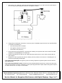
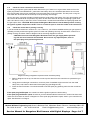
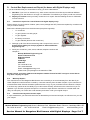
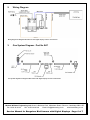
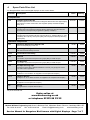
Bangalore Bird Scarer Maintenance Manual
for Bangalore Bird Scarers with Digital Control Boxes
1.
Troubleshooting
A. General situations that will stop your gun working
A.1
Debris in the barrel
Check for rats’ or mice nests in the barrel. These will block the airway in the barrel forcing the gas out of the air
holes in the injector, rather than into the gun. No gas = no bang.
A.2
Flat battery
The battery may have insufficient power to ignite the gas. Replace or recharge the battery.
A.3
Wrong spark plug type
If you replace the spark plug, make sure you fit a long reach rather than a short reach spark plug.
A.4
Spark plug side electrode still in place
If you replace the spark plug, make sure you remove the side electrode.
A.5
Low gas pressure
The gas bottle may be depleted - replace with a full bottle.
A.6
Gas jet core position
If the gas jet core has been removed, make sure it has been re-positioned correctly. The gas jet core in the
wrong position can give a WHUMP rather than a BANG.
A.7
Advanced control panel settings
If the advanced control panel settings have been altered, the amount of gas entering the barrel may be too
great. Too much gas can give a WHUMP rather than a BANG. Refer to your instruction manual.
A.8
Rusty fuse
Check the fuse isn’t corroded. Clean or replace as necessary.
A.9
Dirt in the gas jet
Check the gas jet isn’t blocked. Clean or replace as necessary.
A.10
Corroded battery connectors
Check the battery connectors are corroded. Clean or replace as necessary.
B. The Bangalore Bird Scarer appears dead when connected to the battery. The control box doesn’t illuminate and the control box doesn’t click .
This is likely to be a problem with the electrical connections or the control box.
Michael Williams Engineering Ltd, Queen’s Business Park, Wilbraham Road, Fulbourn, Cambridge CB21 5ET
Tel: 01223 88 22 22
Fax: 01223 88 25 98
Email: [email protected]
www.birdscaring.co.uk
Service Manual for Bangalore Bird Scarers with Digital Displays - Page 1 of 7
B.1
Check the battery connections
Ensure that the RED lead from the control box connects to the POSITIVE (+) terminal on the battery and the
BLACK lead connects to the NEGATIVE (-) terminal. Ensure that good contacts are made with the terminals. If
these leads are connected the wrong way round, or the contact is not good, the Bangalore Bird Scarer will not
function.
B.2
Check the fuse hasn’t blown and isn’t corroded
The fuse is mounted in the RED lead connecting to the POSITIVE (+) battery terminal. Check that the fuse
hasn’t blown.
If the fuse has NOT blown: check that there is no corrosion on the fuse terminals that will prevent the current
flow. Remove, inspect and replace the fuse if required. Clean any corrosion from the fuse’s terminals and the
mushroom ends of the wires in the fuse holder. Give the spring in the fuse holder a slight stretch and re-assemble.
If the control box still doesn’t light up: Check that you have followed all the instructions in sections B1 and
B2 above. If the control box still won’t light up, send it in for repair. See Section D on Page 5 for full details.
C. The control box lights up and clicks but the Bangalore doesn’t fire
This is likely to be a problem with the gas supply or the ignition system. CAUTION: Carry out the following tests in an out-door area where there are no naked flames or other sources of gas ignition. Do not
smoke anywhere near a Bangalore Bird Scarer.
C.1
Check the gas supply
Check your gas bottle isn’t depleted (replace with a full one), check that it’s turned on and check the gas regulator is firmly screwed onto the gas bottle.
C.2
Check the gas system
Carefully note the position of the steel gas jet core in the firing tube - you must replace it in this exact position.
Remove the steel gas jet core from the firing tube and locate the gas jet, mounted at the end.
Very carefully, unscrew the gas jet. Look through the gas jet to see if there are any obstructions. Clean out the
gas jet by very gently blowing through it. Never poke objects into the gas jet to clear it out - you will damage it.
With the gas jet still removed, set the gun to work a few times by pressing the Test Fire button. This flushes the
pipes free of debris. You should be able to hear a hiss of gas from the pipe each time the gun tries to fire.
If you hear the gas hiss: Replace the gas jet into the gas jet core. Ensure the gas jet is screwed tight enough
to prevent gas escaping via the threads. Replace the gas jet core into the firing tube, making sure it’s replaced
in the same position you noted earlier. Hint: you can fine tune the bang by raising or lowering the position of the
gas jet core within the firing tube.
If you DO NOT hear the gas hiss: Check that you have followed all the instructions in sections C1 and C2. If
you still don’t hear the gas hiss, replace the Gas Kit (Part No. B47). See Section 4 on Page 7 for full details.
C.3
Check the ignition system
Check your spark plug first. Check that it is a long reach spark plug and check that the side electrode has been
removed (this forces the spark to jump from the central electrode to the rim of the spark plug).
Test your ignition system as follows.
CAUTION: Disconnect the Bangalore Bird Scarer from the gas supply before proceeding with this test. Potential shock hazard. Do not touch any exposed parts, wires or
the spark plug when performing this test.
Michael Williams Engineering Ltd, Queen’s Business Park, Wilbraham Road, Fulbourn, Cambridge CB21 5ET
Tel: 01223 88 22 22
Fax: 01223 88 25 98
Email: [email protected]
www.birdscaring.co.uk
Service Manual for Bangalore Bird Scarers with Digital Displays - Page 2 of 7
1. Remove the coil, condenser, spark plug and spark plug lead from the gun and connect the spark plug to
the coil using the spark plug lead, as shown in Diagram C3 below:
Diagram C3. Wiring configuration required to test the ignition system.
2. Using pliers to make tight connections, connect a piece of standard single-core wire from the NEGATIVE
(-) terminal of the battery to:
•
the metal clamp of the coil holder
•
the negative connector of the coil
•
the thread of the spark plug
3. Do the same from the POSITIVE (+) terminal of the battery to the positive side of the coil BUT DO NOT
CONNECT IT PERMANENTLY TO THE COIL.
4. Position the spark plug so that you can safely see the tip and so that it is not in direct contact with any
other objects.
5. Briefly touch the live positive wire from the battery onto the positive coil connector. On breaking the connection the spark plug should spark.
If the spark plug DOES spark: the ignition system is working. Replace the ignition system back into the Bangalore Bird Scarer.
If the spark plug DOES NOT spark: Check that you have followed all the instructions in section C3 above and
check the connections as shown in Diagram C3. If the spark plug still doesn’t spark, replace the Ignition Kit (Part
No. B90). See Section 4 on Page 7 for full details.
Michael Williams Engineering Ltd, Queen’s Business Park, Wilbraham Road, Fulbourn, Cambridge CB21 5ET
Tel: 01223 88 22 22
Fax: 01223 88 25 98
Email: [email protected]
www.birdscaring.co.uk
Service Manual for Bangalore Bird Scarers with Digital Displays - Page 3 of 7
C.4
Check for loose connections and corrosion
A perfectly good ignition system will fail when fitted to the gun if there is not a good clean earth run from the
spark plug thread to the NEGATIVE (-) terminal of the battery. Also, the condenser attached to the coil must
have a good earth from its own metal body onto the metal clamp of the coil holder. The wire push on tag contacts must also be sound and the screw top of the spark plug must be tight.
As your gun ages, corrosion will start to interfere with the good earth in the system. If the gun gives ignition trouble, remove all the electrical components, strip down to their bare minimum and give everything a good clean
with a wire brush, emery or wire wool, even if it looks clean. Include the thread where the spark plug seats into
the gas injector stem. CAUTION: Disconnect the Bangalore Bird Scarer from the battery before cleaning
the ignition system components. NOTE: There is no need to open or clean the inside of the control box.
C.5
Check the control box is pulsing correctly
If you have tried the solutions in sections C1, C2, C3 and C4, you will have established that your gas system is
operating correctly and that the ignition system is clean and operating correctly. Check that the control box is
pulsing correctly as follows. Refer to Diagram C6 for the wiring diagram for this test.
CAUTION: Disconnect the Bangalore Bird Scarer from the gas supply before proceeding with this test. Potential shock hazard. Do not touch any exposed parts, wires or
the spark plug when performing this test.
Diagram C6. Wiring configuration required to test the control box pulsing.
1. Refer to Diagram C3 set up, but this time connect up the wires from the control box to operate the ignition coil.
2. Using pliers to make tight connections, connect a piece of standard single-core wire from the metal
clamp of the coil holder to the thread of the spark plug (see Diagram C6).
3. Press the Test Fire button. You should be able to see the spark plug sparking each time the control box
clicks.
If the spark plug DOES spark: the control box and the ignition system are both working.
If the spark plug DOES NOT spark: Check that you have followed all the instructions in section C5 above and
check the connections as shown in Diagram C6. If the spark plug still doesn’t spark, send in your control box for
repair. See Section D on Page 5.
Michael Williams Engineering Ltd, Queen’s Business Park, Wilbraham Road, Fulbourn, Cambridge CB21 5ET
Tel: 01223 88 22 22
Fax: 01223 88 25 98
Email: [email protected]
www.birdscaring.co.uk
Service Manual for Bangalore Bird Scarers with Digital Displays - Page 4 of 7
D. Control Box Replacement and Repair (for boxes with Digital Displays only)
If you have identified that your Control Box is faulty, you have 2 alternatives:
1. New Box: if you are in an extreme hurry, order a new control box from directly from Michael Williams
Engineering Ltd. See Section 4 on Page 7 for full details. This will allow you repair you old box at leisure.
2. Repair your old box: send your faulty control box in for repair. See the following section for full details
on how to do this.
D.1
Control box repairs for Control Boxes with digital displays only.
Repair charge: £75.00 (inclusive of labour, parts, return postage and VAT). Boxes are repaired by ourselves and
carry a 6-month warranty.
Remove the following items from the bird scarer (see picture opposite):
•
1 x control box
•
1 x gas injection core with gas jet
•
1 x gas regulator
•
2 x battery connectors
•
1 x gas solenoid (built into the control box)
3. Package up all of the above items along with a cheque for the sum of
£75.00 (Please make your cheque payable to “Michael Williams
Engineering Ltd”.
Parts to send away for control box
repairs.
4. Send your control box, parts, name, address, telephone number and
cheque to:
Michael Williams Engineering Ltd
Queen’s Business Park
Wilbraham Road
Fulbourn
Cambridge
CB21 5ET
Tel: 01223 88 22 22
Fax: 01223 88 25 98
Email: [email protected]
Please mark your package for the attention of Tim.
Please enclose your name, address and telephone number. Please DO NOT send your control box to
any other company for repair.
D.2
Warranty Repairs
The control boxes of new Bangalore Bird Scarers are covered by a 12-month warranty from the date of purchase. Repaired control boxes are covered by a 6-month warranty from the date of repair. If your control box is
covered under either of these warranties, please enclose a copy of your purchase invoice instead of a cheque.
If we have any queries as to the validity of your claim under warranty, we will return the control box to you unrepaired. If you enclose a payment cheque for a control box repair and the control box is covered under warranty, we will repair your control box under warranty and return it with your original cheque.
D.3
Control boxes beyond economic repair
If, upon assessment, your returned control box is deemed beyond economical repair, we will return it to you with
your cheque.
Michael Williams Engineering Ltd, Queen’s Business Park, Wilbraham Road, Fulbourn, Cambridge CB21 5ET
Tel: 01223 88 22 22
Fax: 01223 88 25 98
Email: [email protected]
www.birdscaring.co.uk
Service Manual for Bangalore Bird Scarers with Digital Displays - Page 5 of 7
2.
Wiring Diagram
Wiring diagram for Bangalore Bird Scarers with digital displays on their control boxes
3.
Gas System Diagram - Part No B47
Gas system diagram for Bangalore Bird Scarers with digital displays on their control boxes
Michael Williams Engineering Ltd, Queen’s Business Park, Wilbraham Road, Fulbourn, Cambridge CB21 5ET
Tel: 01223 88 22 22
Fax: 01223 88 25 98
Email: [email protected]
www.birdscaring.co.uk
Service Manual for Bangalore Bird Scarers with Digital Displays - Page 6 of 7
4.
Spare Parts Price List
For Bangalore Bird Scarers with digital displays on their control boxes.
Part No
Description
Price
Delivery
Complete Control Box Kit
£214.00
£10.00
Complete Ignition System
£41.50
£7.00
£106.00
£7.00
Spark Plug Suppression (Speed) Lead
£7.90
£5.00
Spark Plug for Bangalore Bird Scarers
£3.30
£5.00
Coil-Condenser Assembly
£30.80
£5.00
Solenoid
£36.00
£5.00
Gas Regulator
£31.50
£5.00
Gas Pipe Securing Clips
£0.50
Free
Gas Pipe Tail Piece for Gas Kit
£2.00
£0.50
Elbow for Gas Kit
£2.80
£0.50
Injector Core for Gas Kit
£5.50
£3.00
Gas Jet
£2.50
£2.00
Complete Kits
B38
B90
B47
Complete replacement control box kit for Bangalore Bird Scarers with digital display
control boxes. Includes Control Box, Gas Regulator (B109) and Solenoid (B29).
Ready to fit.
Complete with Coil Condenser Assembly (B108), Spark Plug with side electrode
removed (B111) and Spark Plug Suppression (Speed) Lead (B31).
Complete Gas Kit
Complete with Gas Regulator (B109), Gas Pipe (B14) x 2, Tailpiece (B30) x 2, Solenoid (B29), Elbow (B112), Gas Injector (B50), Gas Jet (B2) and Gas Pipe Securing
Clip Kit (B25).
Individual Components
B31
B111
B108
B29
B109
B25
B30
B112
B50
B2
Connects the spark plug to the coil.
With side electrode already removed.
You will also require the Gas Pipe Securing Clips (B25) to install this part.
You will also require the Gas Pipe Securing Clips (B25) to install this part.
Contains gas hose clips of different diameters to secure your gas pipe in accordance with current regulations.
1/8” BSPT to 1/4” Tail Piece. As supplied in the Complete Gas Kit (B47)
90-degree 1/4” to 1/4” BSP connector. As supplied in the Complete Gas Kit (B47)
As upplied in the Complete Gas Kit (B47)
As supplied in the Complete Gas Kit (B47)
All prices exclude VAT.
Order online at
www.birdscaring.co.uk
or telephone 01223 88 22 22
Michael Williams Engineering Ltd, Queen’s Business Park, Wilbraham Road, Fulbourn, Cambridge CB21 5ET
Tel: 01223 88 22 22
Fax: 01223 88 25 98
Email: [email protected]
www.birdscaring.co.uk
Service Manual for Bangalore Bird Scarers with Digital Displays - Page 7 of 7